manuals.online logo
Brands
  1. Home
  2. •
  3. Brands
  4. •
  5. ABB
  6. •
  7. Controllers
  8. •
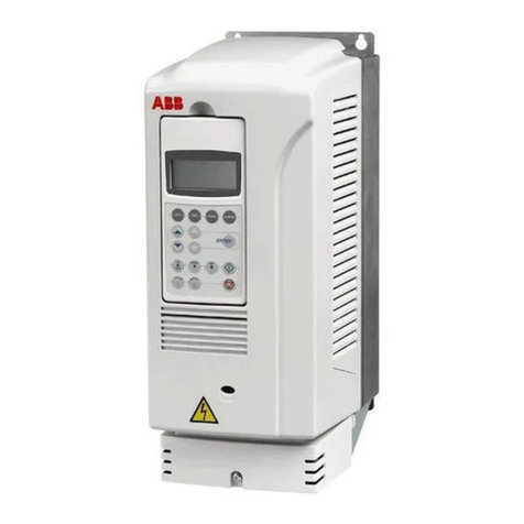
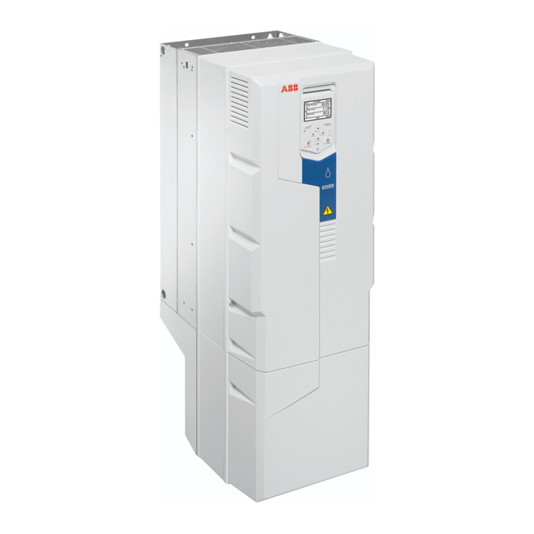
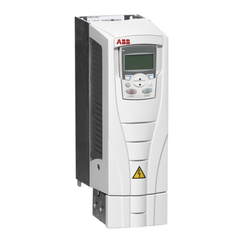
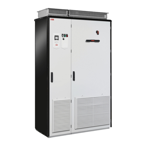
  9. ABB ACS880-01 Series User manual

ABB ACS880-01 Series User manual

Other manuals for ACS880-01 Series

15

This manual suits for next models

23

Other ABB Controllers manuals

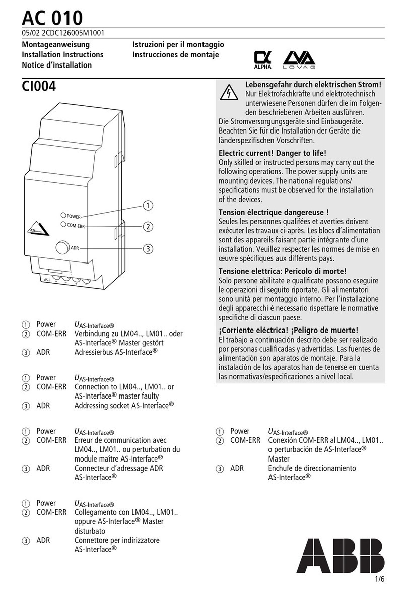
ABB AC500-eCo Starter-Kit User manual

ABB

ABB AC500-eCo Starter-Kit User manual

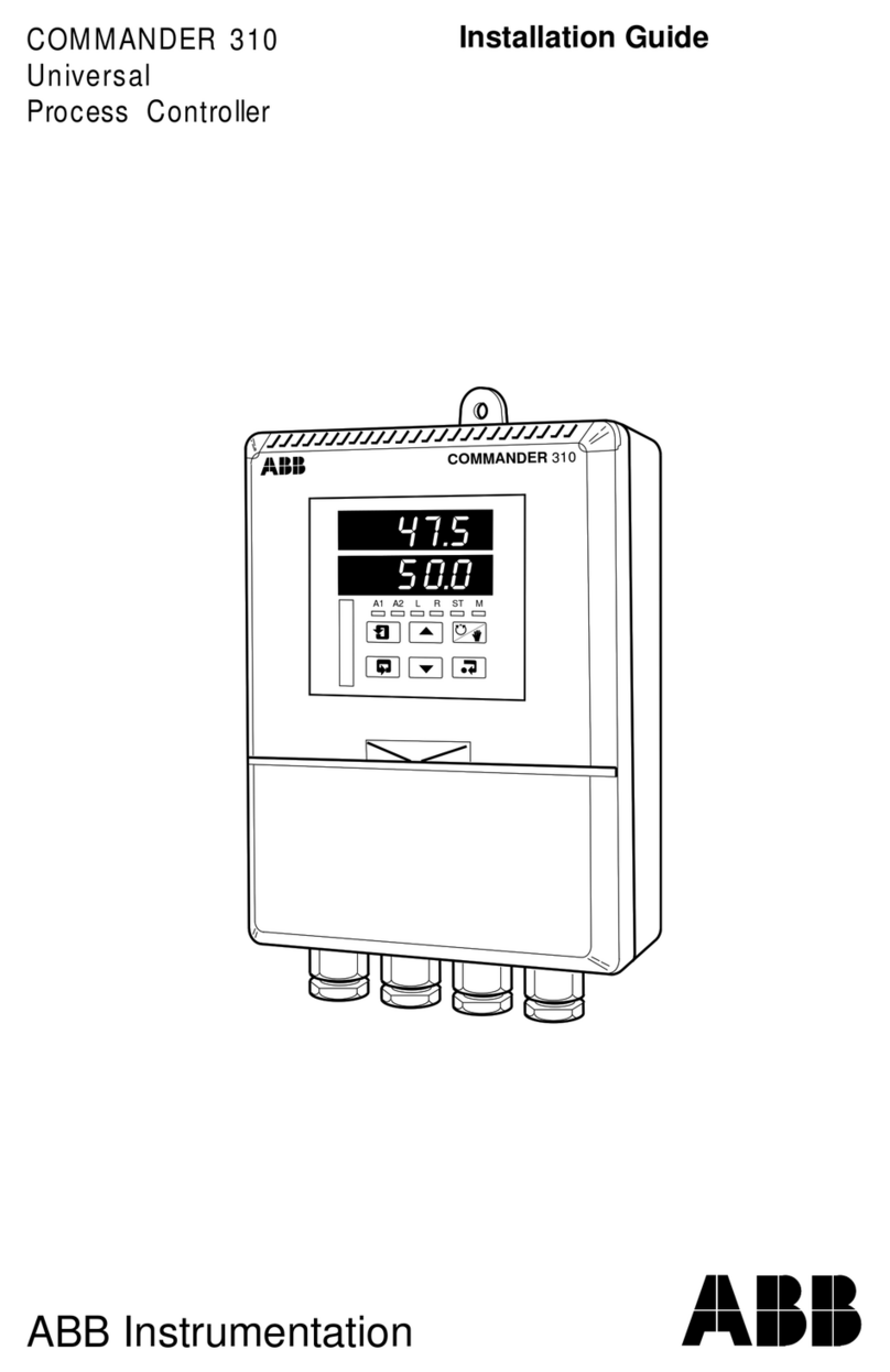
ABB AC 31 User manual

ABB

ABB AC 31 User manual

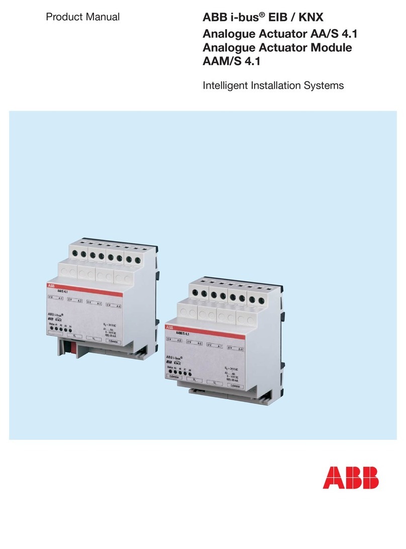
ABB ACS880 Series Use and care manual

ABB

ABB ACS880 Series Use and care manual

ABB Relion 670 series REC670 User manual

ABB

ABB Relion 670 series REC670 User manual

ABB FC/S 1.1 User manual

ABB

ABB FC/S 1.1 User manual

ABB ACS800-17 User manual

ABB

ABB ACS800-17 User manual

ABB ACS880-01 Series User manual

ABB

ABB ACS880-01 Series User manual

ABB C320 User manual

ABB

ABB C320 User manual

ABB PSE18 Guide

ABB

ABB PSE18 Guide

ABB 300 Series User manual

ABB

ABB 300 Series User manual

ABB M2301 User manual

ABB

ABB M2301 User manual

ABB UMC22-FBP Parts list manual

ABB

ABB UMC22-FBP Parts list manual

ABB Shunt Trip AA User manual

ABB

ABB Shunt Trip AA User manual

ABB NextMove e100 User manual

ABB

ABB NextMove e100 User manual

ABB Relion 670 series Quick start guide

ABB

ABB Relion 670 series Quick start guide

ABB Relion 670 series User manual

ABB

ABB Relion 670 series User manual

ABB Contrac RSD Series User manual

ABB

ABB Contrac RSD Series User manual

ABB ControlMaster CM10 User manual

ABB

ABB ControlMaster CM10 User manual

ABB COM600S IEC User manual

ABB

ABB COM600S IEC User manual

ABB TZIDC User manual

ABB

ABB TZIDC User manual

ABB IRC5 Compact User manual

ABB

ABB IRC5 Compact User manual

ABB ACS580-07-0495A-4 User manual

ABB

ABB ACS580-07-0495A-4 User manual

ABB ACS55-01E-01A4-2 User manual

ABB

ABB ACS55-01E-01A4-2 User manual

ABB COM600 series User manual

ABB

ABB COM600 series User manual
Popular Controllers manuals by other brands

Sunricher SR-ZV9003T3-RGBW-US Installation

Sunricher

Sunricher SR-ZV9003T3-RGBW-US Installation

Ksenia intro Installation and configuration manual

Ksenia

Ksenia intro Installation and configuration manual

Inovance CAN200 Series manual

Inovance

Inovance CAN200 Series manual

Gauzy LC6 FLEX Controller Installation and operation guide

Gauzy

Gauzy LC6 FLEX Controller Installation and operation guide

Viking SLP-1 Technical practice

Viking

Viking SLP-1 Technical practice

CKD KBX-30E-U Series instruction manual

CKD

CKD KBX-30E-U Series instruction manual

Sharp Energy Sun Flux User manual & installation guide

Sharp Energy

Sharp Energy Sun Flux User manual & installation guide

Yamaha RCX40 user manual

Yamaha

Yamaha RCX40 user manual

AB Quality PowerFlex 400 Frames D-H Service bulletin

AB Quality

AB Quality PowerFlex 400 Frames D-H Service bulletin

Yamaha MJC8 owner's manual

Yamaha

Yamaha MJC8 owner's manual

AL-KO ATC operating instructions

AL-KO

AL-KO ATC operating instructions

Savant SmartControl 2 Deployment guide

Savant

Savant SmartControl 2 Deployment guide

GameSir T3S user manual

GameSir

GameSir T3S user manual

Kostal inveor operating manual

Kostal

Kostal inveor operating manual

Emerson Yarway 20-55 Operating and safety instructions

Emerson

Emerson Yarway 20-55 Operating and safety instructions

CoCo ACM-LV24 Quick installation guide

CoCo

CoCo ACM-LV24 Quick installation guide

Brooks SLA5810/20 Installation and operation manual

Brooks

Brooks SLA5810/20 Installation and operation manual

SIGMA TEK SR 011 Technical manual

SIGMA TEK

SIGMA TEK SR 011 Technical manual

manuals.online logo
manuals.online logoBrands
  • About & Mission
  • Contact us
  • Privacy Policy
  • Terms and Conditions

Copyright 2025 Manuals.Online. All Rights Reserved.

English . . . . . . . . 3
English – USA . . 7
Dansk . . . . . . . . 13
Deutsch . . . . . . 17
Español. . . . . . . 23
Suomi . . . . . . . . 29
Français . . . . . . 33
Italiano . . . . . . . 39
Nederlands . . . . 45
Polski . . . . . . . . 49
Português . . . . . 55
Русский . . . . . . 61
Svenska . . . . . . 67
Türkçe. . . . . . . . 71
中文 . . . . . . . . . 75
EN
USA
DA
DE
ES
FI
FR
IT
NL
PL
PT
RU
SV
TR
ZH
ABB industrial drives
Quick installation guide
ACS880-01 drives
Frames R1 to R3
List of related manuals
You can find manuals and other product documents in PDF format on the Internet. See section
Document library on the Internet on the inside of the back cover. For manuals not available in the
Document library, contact your local ABB representative.
The QR code below opens an online listing of the manuals applicable to this product.
ACS880-01 manuals
Drive hardware manuals and guides Code (English)
ACS880-01 hardware manual 3AUA0000078093
ACS880-01 quick installation guide for frames R1 to R3 3AUA0000085966
ACS880-01 quick installation guide for frames R4 and R5 3AUA0000099663
ACS880-01 quick installation guide for frames R6 to R9 3AUA0000099689
ACS880-01 +P940 drives for cabinet installation
supplement
3AUA0000145446
ACS880-01 assembly drawings for cable entry boxes of
IP21 frames R5 to R9
3AUA0000119627
ACS-AP-x assistant control panels user’s manual 3AUA0000085685
Vibration dampers for ACS880-01 drives (frames R4 and
R5, option +C131) installation guide
3AXD50000010497
Vibration dampers for ACS880-01 drives (frames R6 to
R9, option +C131) installation guide
3AXD50000013389
ACS880-01 +C132 marine type-approved drives
supplement
3AXD50000010521
ACS880-01 +N7502 drives for SynRM motors (0.8 to 200
kW) supplement
3AXD50000029482
Drive firmware manuals and guides
ACS880 primary control program firmware manual 3AUA0000085967
Quick start-up guide for ACS880 drives with primary
control program
3AUA0000098062
Option manuals and quides
Manuals and quick guides for I/O extension modules,
fieldbus adapters, etc.
3AUA0000085966 Rev G
MUL
EFFECTIVE: 2017-05-15
2017 ABB Oy. All Rights Reserved.
EN – Quick installation guide 3
EN
DA
DE
ES
FI
FR
IT
NL
PT
RU
SV
TR
CN
EN – Quick installation guide
This guide instructs briefly how to install the drive. For more detailed instructions,
engineering guide lines, technical data and complete safety instructions, see the
hardware manual (www.abb.com/drives: Select Document Library and search for
document number 3AUA0000078093 [English]).
Follow the safety instructions
The floor material below the drive must be non-flammable.
Select the power cables
Size the power cables according to local regulations to carry the nominal current
given on the type designation label of your drive.
Typical power cable sizes are listed in table Jon page 82. For the conditions of the
sizing, see the hardware manual.
Ensure the cooling
See table Bon page 79 for the losses and the cooling air flow through the drive. The
allowed operating temperature range of the drive without derating is -15 to +40 °C.
Protect the drive and input power cable
See table Bon page 79. Check that the operating time of the fuse is below 0.5
seconds.
WARNING! Ignoring the following instructions can cause physical injury or
death, or damage to the equipment:
• Only qualified electricians are allowed to install and maintain the drive.
• Never work on the drive, motor cable or motor when main power is applied.
After disconnecting the input power, always wait for 5 min to let the intermediate
circuit capacitors discharge before you start working on the drive, motor or
motor cable.
• Do not work on the control cables when power is applied to the drive or to the
external control circuits.
• Make sure that debris from borings and grindings does not enter the drive when
installing.
• Do not connect the drive to a voltage higher than what is marked on the type
designation label.
3AUA0000085966 Rev G
4 EN – Quick installation guide
EN
DA
DE
ES
FI
FR
IT
NL
PT
RU
SV
TR
CN
Install the drive on the wall
See figure A on page 79.
Check the insulation of the input and motor cables and the
motor
Check the insulation of the input cable according to local regulations before
connecting it to the drive.
Check the insulation of the motor cable and motor when the cable is disconnected
from the drive, see figure Fon page 80. Measure the insulation resistance between
each phase conductor and the Protective Earth conductor using a measuring voltage
of 1000 V DC. The insulation resistance of an ABB motor must exceed 100 Mohm
(reference value at 25 °C or 77 °F). For the insulation resistance of other motors,
please consult the manufacturer’s instructions. Note: Moisture inside the motor
casing will reduce the insulation resistance. If moisture is suspected, dry the motor
and repeat the measurement.
Connect the power cables
See figures C, D, Eand G. Use symmetrical shielded cable for motor cabling.
1. Undo the mounting screws at the sides of the front cover.
2. Remove the cover by sliding it forward.
3. Attach the residual voltage warning sticker in the local language to the control
panel mounting platform.
4. Remove the rubber grommets from the lead-through plate for the cables to be
connected.
5. IP21 units: Fasten the cable connectors (included in the delivery in a plastic bag)
to the cable lead-through plate holes.
6. Prepare the ends of the input power and motor cables as illustrated in the figure.
7. Ground the cable shields 360 degrees in the cable connectors (IP21 units) or
under the clamps (IP55 units).
8. Connect the twisted shield of the input cable to the PE terminal.
9. Connect the PE conductor of the input cable to the additional PE terminal.
10. Connect the twisted shield of the motor cable and resistor cable (if present) to the
grounding terminal.
11. Connect the phase conductors of the input, motor and resistor cables. Tighten the
screws.
12. Install the control cable grounding shelf in the cable entry box.
EN – Quick installation guide 5
EN
DA
DE
ES
FI
FR
IT
NL
PT
RU
SV
TR
CN
13. Secure the cables mechanically outside the drive.
14. Ground the motor cable shield at the motor end. For minimal interference, make a
360-degree grounding at the cable lead-through, or keep the pig tail short.
Connect the control cables
See figure H.
1. Cut adequate holes into the rubber grommets and slide the grommets onto the
cables. Slide the cables through the holes of the bottom plate and attach the
grommets to the holes.
2. Strip the cable ends and cut to suitable length (note the extra length of the
grounding conductors).
3. Ground the outer shields of all control cables 360 degrees at a grounding clamp in
the cable entry box.
4. Ground the pair-cable shields to the grounding clamp. Leave the other end of the
shields unconnected or ground them indirectly via a high-frequency capacitor with
a few nanofarads, eg, 3.3 nF / 630 V.
5. Connect the conductors to the appropriate terminals of the control board (see
page 6).
6. Wire the optional modules if included in the delivery.
7. Reinstall the front cover.
Note for fieldbus cabling. See figure I.
1. Install the additional grounding shelf.
2. Ground the outer shields of the cables 360 degrees at a grounding clamp.
3. Knock out holes in the cable entry box cover for the cables to be installed. Install
the cable entry box cover.
4. Plug the connector to the fieldbus module.
Default I/O connections
The default I/O connections of the Factory macro of the ACS880 primary control
program are shown below.
6 EN – Quick installation guide
EN
DA
DE
ES
FI
FR
IT
NL
PT
RU
SV
TR
CN
XPOW External power input
1+24VI 24 V DC, 2 A
2GND
XAI Reference voltage and analog inputs
1+VREF 10 V DC, RL1…10 kohm
2-VREF -10 V DC, RL1…10 kohm
3AGND Ground
4AI1+ Speed reference 0(2)…10 V, Rin >
200 kohm
5AI1-
6AI2+ By default not in use. 0(4)…20 mA, Rin =
100 ohm
7AI2-
J1 J1 AI1 current/voltage selection jumper
J2 J2 AI2 current/voltage selection jumper
XAO Analog outputs
1AO1 Motor speed rpm 0…20 mA, RL<
500 ohm
2AGND
3AO2 Motor current 0…20 mA, RL< 500 ohm
4AGND
XD2D Drive-to-drive link
1B
Drive-to-drive link
2A
3BGND
J3 J3 Drive-to-drive link termination switch
XRO1, XRO2, XRO3 Relay outputs
11 NC Ready
250 V AC / 30 V DC
2 A
12 COM
13 NO
21 NC Running
250 V AC / 30 V DC
2 A
22 COM
23 NO
31 NC Faulted(-1)
250 V AC / 30 V DC
2 A
32 COM
33 NO
XD24 Digital interlock
1DIIL Run enable
2+24VD +24 V DC 200 mA 1)
3DICOM Digital input ground
4+24VD +24 V DC 200 mA 1)
5DIOGND Digital input/output ground
J6 Ground selection switch
XDIO Digital input/outputs
1DIO1 Output: Ready
2DIO2 Output: Running
XDI Digital inputs
1DI1 Stop (0) / Start (1)
2DI2 Forward (0) / Reverse (1)
3DI3 Reset
4DI4 Acceleration & deceleration select
5DI5 Constant speed 1 (1 = On)
6DI6 By default not in use.
XSTO Safe torque off
1OUT1
Safe torque off. Both circuits must be
closed for the drive to start.
2SGND
3IN1
4IN2
X12 Safety functions module connection
X13 Control panel connection
X205 Memory unit connection
Wire sizes:
0.5 … 2.5 mm2
(24…12 AWG)
Tightening
torques: 0.5 N·m
(5 lbf·in) for both
stranded and
solid wiring.
1) Total load
capacity of these
outputs is 4.8 W
(200 mA / 24 V)
minus the power
taken by DIO1 and
DIO2.
Fault
EN – USA quick installation guide 7
DA
USA
DA
DE
ES
FI
FR
IT
NL
PT
RU
SV
TR
CN
EN – USA quick installation guide
This guide instructs briefly how to install the drive. For more detailed instructions,
engineering guide lines, technical data and complete safety instructions, see the
hardware manual (www.abb.com/drives: Select Document Library and search for
document number 3AUA0000078093 [English]).
Follow the safety instructions
The floor material below the drive must be non-flammable.
Select the power cables
Select the power cables according to local regulations to carry the nominal current
given on the type designation label of your drive.
Typical power cable sizes are listed in table Jon page 82. For the conditions of the
sizing, see the hardware manual.
Ensure the cooling
See table Bon page 83 for the losses and the cooling air flow through the drive. The
allowed operating temperature range of the drive without derating is -5 to +104 °F.
Protect the drive and input power cable
See table Bon page 83. Check that the operating time of the fuse is below 0.5
seconds.
WARNING! Ignoring the following instructions can cause physical injury or
death, or damage to the equipment:
• Only qualified electricians are allowed to install and maintain the drive.
• Never work on the drive, motor cable or motor when main power is applied.
After disconnecting the input power, always wait for 5 min to let the intermediate
circuit capacitors discharge before you start working on the drive, motor or
motor cable.
• Do not work on the control cables when power is applied to the drive or to the
external control circuits.
• Make sure that debris from borings and grindings does not enter the drive when
installing.
• Do not connect the drive to a voltage higher than what is marked on the type
desgnation label.
8 EN – USA quick installation guide
DA
USA
DA
DE
ES
FI
FR
IT
NL
PT
RU
SV
TR
CN
Install the drive on the wall
See figure A on page 83.
Check the insulation of the input and motor cables and the
motor
Check the insulation of the input cable according to local regulations before
connecting it to the drive.
Check the insulation of the motor cable and motor when the cable is disconnected
from the drive, see figure Fon page 84. Measure the insulation resistance between
each phase conductor and the Protective Earth conductor using a measuring voltage
of 1000 V DC. The insulation resistance of an ABB motor must exceed 100 Mohm
(reference value at 25 °C or 77 °F). For the insulation resistance of other motors,
please consult the manufacturer’s instructions. Note: Moisture inside the motor
casing will reduce the insulation resistance. If moisture is suspected, dry the motor
and repeat the measurement.
Connect the power cables
See figures C, Dand Eon page 83 and 84.
1. Undo the two mounting screws at the sides of the front cover.
2. Remove the cover by sliding it forward.
3. Attach the residual voltage warning sticker in the local language to the control
panel mounting platform.
4. Remove the rubber grommets from the lead-through plate for the cables to be
connected.
5. Fasten the cable conduits to the cable lead-through plate holes. Strip the cable
ends. Slide the cables through the connectors.
6. Connect the grounding conductors to the grounding terminals.
7. Connect the phase conductors of the input and motor cables. Tighten the screws.
8. Units with option +D150: Connect the brake resistor cable conductors to the R+
and R- terminals.
9. Install the control cable grounding shelf in the cable entry box.
10. Connect the motor cable at the motor end.
Connect the control cables
See figure Gon page 84.
EN – USA quick installation guide 9
DA
USA
DA
DE
ES
FI
FR
IT
NL
PT
RU
SV
TR
CN
1. Fasten the cable conduits to the cable lead-through plate holes. Slide the cables
through the connectors.
2. Strip the cable ends and cut to suitable length (note the extra length of the
grounding conductors).
3. Ground the outer shields of all control cables 360 degrees at a grounding clamp in
the cable entry box.
4. Ground the pair-cable shields to the grounding clamp. Leave the other end of the
shields unconnected or ground them indirectly via a high-frequency capacitor with
a few nanofarads, eg, 3.3 nF / 630 V.
5. Connect the conductors to the appropriate terminals of the control board (see
page 10).
6. Wire the optional modules if included in the delivery. For fieldbus cabling, see
page 81.
7. Reinstall the front cover.
Default I/O connections
The default I/O connections of the Factory macro of the ACS880 primary control
program are shown below.
10 EN – USA quick installation guide
DA
USA
DA
DE
ES
FI
FR
IT
NL
PT
RU
SV
TR
CN
XPOW External power input
1+24VI 24 V DC, 2 A
2GND
XAI Reference voltage and analog inputs
1+VREF 10 V DC, RL1…10 kohm
2-VREF -10 V DC, RL1…10 kohm
3AGND Ground
4AI1+ Speed reference 0(2)…10 V, Rin >
200 kohm
5AI1-
6AI2+ By default not in use. 0(4)…20 mA, Rin =
100 ohm
7AI2-
J1 J1 AI1 current/voltage selection jumper
J2 J2 AI2 current/voltage selection jumper
XAO Analog outputs
1AO1 Motor speed rpm 0…20 mA, RL<
500 ohm
2AGND
3AO2 Motor current 0…20 mA, RL< 500 ohm
4AGND
XD2D Drive-to-drive link
1B
Drive-to-drive link
2A
3BGND
J3 J3 Drive-to-drive link termination switch
XRO1, XRO2, XRO3 Relay outputs
11 NC Ready
250 V AC / 30 V DC
2 A
12 COM
13 NO
21 NC Running
250 V AC / 30 V DC
2 A
22 COM
23 NO
31 NC Faulted(-1)
250 V AC / 30 V DC
2 A
32 COM
33 NO
XD24 Digital interlock
1DIIL Run enable
2+24VD +24 V DC 200 mA 1)
3DICOM Digital input ground
4+24VD +24 V DC 200 mA 1)
5DIOGND Digital input/output ground
J6 Ground selection switch
XDIO Digital input/outputs
1DIO1 Output: Ready
2DIO2 Output: Running
XDI Digital inputs
1DI1 Stop (0) / Start (1)
2DI2 Forward (0) / Reverse (1)
3DI3 Reset
4DI4 Acceleration & deceleration select
5DI5 Constant speed 1 (1 = On)
6DI6 By default not in use.
XSTO Safe torque off
1OUT1
Safe torque off. Both circuits must be
closed for the drive to start.
2SGND
3IN1
4IN2
X12 Safety functions module connection
X13 Control panel connection
X205 Memory unit connection
Wire sizes:
0.5 … 2.5 mm2
(24…12 AWG)
Tightening
torques: 0.5 N·m
(5 lbf·in) for both
stranded and
solid wiring.
1) Total load
capacity of these
outputs is 4.8 W
(200 mA / 24 V)
minus the power
taken by DIO1 and
DIO2.
Fault