Hagstrom KEAD6 User manual

KEAD6
USB Joystick Interface
and Keyboard Encoder
User Manual
Toll Free 888-690-9080
Phone: (540) 465-4677 Fax: (540) 465-4678
Monday through Friday, 8:00 am to 5:00 pm (EST)
www.hagstromelectronics.com
1986 Junction Road, Strasburg, VA 22657
Copyright © 2016 HAGSTROM ELECTRONICS, INC.
V. 07.16
HAGSTROM
ELECTRONICS, INC.

Table of Contents
Introduction to the KEAD6 1
Computer Connections and Device ID Jumper 2
Interfacing to the KEAD6 3
The KEAD6.EXE Program 4
The Program Screen 5
File Menu Selections 6
Options Menu Selections 8
Configuring the KEAD6 9
KEAD6 Operating Tips 19
Error Messages 20
Appendix A: KEAD6 Specifications 22
Appendix B: Using the KEAD6 with Custom Software 23
Accessories 24
Thank you for purchasing the
HAGSTROM ELECTRONICS, INC.
KEAD6. This product is configurable in a variety
of ways to meet your specific requirements.
Please take a few minutes to read this manual
before using your KEAD6.
Warranty
HAGSTROM ELECTRONICS, INC. warrants this
product against defects in material or workmanship for a
period of ONE YEAR fromtheoriginal purchase date. We will
repair or replace (at our option) thereturned defective unit
at no charge during this warranty period.
No responsibility is assumed for any special, incidental,
or consequential damage resulting fromthe use ofor
inability to use this product. In no case is HAGSTROM
ELECTRONICS, INC. to be liable for any amount which
exceeds thepurchase price ofthe unit, regardless ofthe
claim.
No other warranty, written or verbal, is authorized. This
warranty is applicable only to units sold inthe United States.
Units sold outside the United States are covered by a similar
warranty.
Depending on the state in which you live, you may have additional rights.
Great care has been taken during the assembly, testing, and burn-in
of your KEAD6 to ensure itsperformance. If youhave any questions,
please send us an email or give us a call. Support is available Monday
through Friday, 8:00 am to 5:00 pm (EST).
Call Toll Free 888-690-9080, or (540) 465-4677
NOTICE The KEAD6 product is designed to be used by technically
oriented computer users. When the KEAD6 is in use, your computer’s
signals and voltages are present on the unit. Prudent handling and
packaging is necessary to prevent damage to your computer.
Your keyboard encoder is designed for OEM use, and is not FCC part 15 approved. Because
the packaging and use oftheproduct will directly affect the characteristics ofthe unit, it isthe
responsibility of the purchaser to obtain final approval of their application, if required.

1
Introduction to the KEAD6
Our KEAD6 Interface is a product designed to interface potentiometers
to the computer’s USB port.Potentiometers connected to the KEAD6
input channels produce joystick axis movement and/or keystrokes on
the PC.
The KEAD6 is fully programmable by the user. This programmability
feature allows the configuration of each input channel according to the
joystick axis and/or keystrokes to be emulated by the potentiometer
connected to that particular input. Each input of the KEAD6 may be
programmed to emulate a joystick axis, send keystrokes based on
the potentiometer movement, or both joystick and keystrokes from a
single channel. The KEAD6 stores the user’s configuration program in
non-volatile memory so that the configuration information isretained
on the unit even after power is turned off.The KEAD6 configuration
may be changed using the included software as many times as
required for various applications.
The KEAD6 Input Channels
The KEAD6 features six input channels with screw terminals to easily
connect potentiometers. Three Joystick Buttons are also provided.
Power Requirements
The KEAD6 requires no external power source. It is powered directly
from the USB port on the PC.
Supported Computers
All PCs with a standard USB port will work with the KEAD6. The
KEAD6.EXE configuration program is for Windows based systems.
Hardware Requirements
The KEAD6 is designed to work with standard, commercially available
cables for connection to the PC. A standard A-B Type USB cable is
required for this connection.
Default Settings
The KEAD6 is programmed and shipped with a default configuration
with keystrokes from all channels disabled.
24
Accessories
KE-USBMM6
6 foot USB Type A to Type B connecting
cable between KEAD6 and PC.
MTA100-4-12
Cable set for use with KEAD6 Joystick But-
ton inputs, 4 wires, each 12 inches long.
Terminated with a 4 position connector on
one end with loose wires at the other end.

Computer Connections
There isone USB connector located onthe KEAD6. Connection
to this port can be made with power on as the KEAD6 supports
“Hot Plug” operation as a USB device. When the KEAD6 is
plugged into a PC for the first time, the appropriate standard
drivers are loaded by the operating system.
The KEAD6 emulates both a USB joystick and a standard USB
keyboard. The KEAD6 may be used in addition to or inplace of
the system’s own keyboard.
2 23
Appendix B:
Using the KEAD6 with Custom Software
In addition to converting potentiometer movement to keystrokes
or joystick action, the KEAD6 input channels can also be used
as an analog to digital converter. The current voltage level of
each channel can be read as an 8 bit value by the user’s custom
software utilizing the KEAD6.dll which is located ontheincluded
CD-ROM.
A Visual Basic sample program demonstrating how to read
the digital values fromthe KEAD6 inputs isincluded onthe
CD-ROM under the KEAD6_Sample folder. The source code for
this sample is also located under this folder.
*Note: We recommend disabling all scanned channels on the
KEAD6 when used strictly as an analog to digital converter. To
disable the channels, use the KEAD6 configuration utility.
Device ID Jumper
Two KEAD6 units may be connected to
the same computer and programmed
independently. If using one unit, leave
the Device ID jumper open (factory
default). If using two KEAD6 units,
leave the jumper open on unit 1 and
closed on unit 2. This setup will present
two different USB devices to the system
that both work as USB keyboards.

Interfacing to the KEAD6
The three-position screw terminal blocks onthe KEAD6 are
used to connect potentiometers to the unit. The potentiometers
used with each KEAD6 input can range in value from 500Ωup
to 1MΩ. Potentiometers are connected to the +5V, Wiper input,
and Ground as shown below.
322
Operating Voltage 5 Volts DC +/- 5%
Operating Current 15 ma Typical
+potentiometers
Operating Temp. 0 to 70 Degrees C
PC Interface USB
Potentiometer Range 500Ωto 1MΩ
Appendix A:
KEAD6 Specifications
2.7”
3.0”
.125”
Dia. (4)
Wiper
+5V
Ground
Three Joystick Buttons
The four position header on the KEAD6 provides three inputs
and a logic ground signal. To activate an input, short it to the
provided logic ground through a switch. The activation ofthe
switch will create a joystick button press on the computer.
Button 3
Button 2
Button 1
Gnd

21
The KEAD6.EXE Program
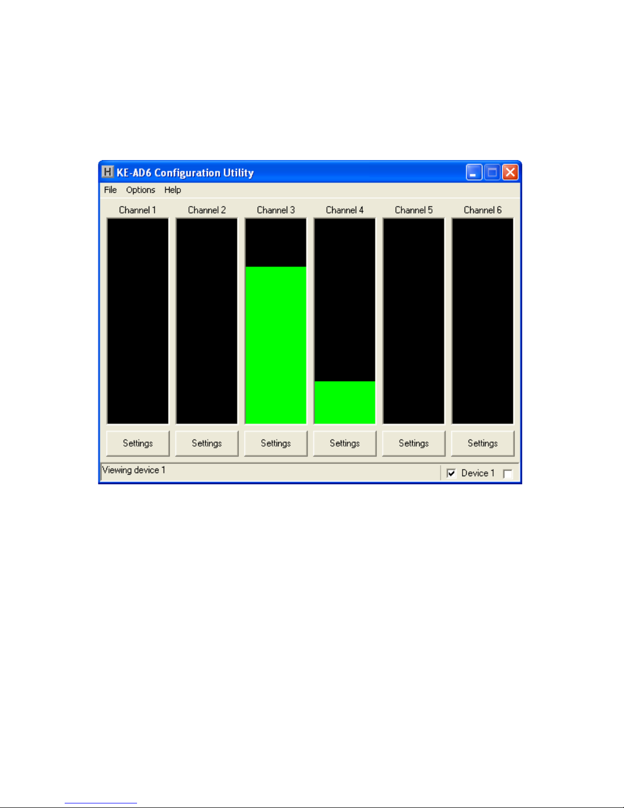
The KEAD6 unit is shipped with a CD-ROM containing the KEAD6.
EXE utility program which is used for configuring the unit. The
configuration program allows selection of whether the channel
is to emulate a joystick axis, keystrokes,or both.Additional
adjustable parameters include defining the number of response
steps per channel, the keystrokes generated by each step, and
other tuning options.
Getting Started
To use and configure the KEAD6, follow the steps listed below.
1. Attach the KEAD6 to the computer as described on
page 2 under the section “Computer Connections.”
2. Insert the CD and save the content to its own folder
on thehard drive. The CD may now be removed and
stored in a safe location for future use.
3. Open the folder that was created in step 2 and start
the configuration program by selecting the program
file KEAD6.EXE.
*Note: The programs must be copied to and run from its own
folder on the PC’s hard drive. The CD itself should be reserved
for backup purposes only.
4
*Note: When the KEAD6.EXE program is running, joystick
movement and keystrokes will no longer be produced by the
KEAD6 until the program is closed again. This disable mode
prevents any conflicts that may arise between the KEAD6
programmed responses and the configuration program.
“Invalid configuration”
“Invalid configuration file”
When loading an already existing configuration from a file or
uploading a configuration fromthe KEAD6, theprogram will
give this error message ifthe file is corrupted or ifit isthe wrong
file type.
“Error opening the file”
This error message is shown ifthe KEAD6.EXE program attempts
to open a file that is already open in another application. If this
happens, close the other application and open the file again.
“Error saving file”
This error message is shown ifthe KEAD6.EXE program attempts
to save a file that is already open in another application, or if
there is not enough disk space. If this happens, close theother
application and try saving the file again.
“Error while writing to the KEAD6”
This indicates that, while the computer can communicate with
the KEAD6, it was not able to read or write the configuration.
Communication may be interrupted if a user presses a key on
the keyboard or if another program takes the focus away from
the KEAD6 application. If this error message is displayed, load
the configuration again.

The Program Screen
The main program screen displays graphs ofthe current
positions of each of the six channels corresponding to the six
potentiometers on the KEAD6.
520
Switching Selected Device
If two KEAD6 units with properly assigned Device ID jumpers (see
page 2, section “Device ID Jumper“) are both connected to the
PC, then the KEAD6.EXE program must be set to which device
to monitor. In the lower right corner of the main screen there
are two checkboxes which are used to switch between Device
1 (left box) and Device 2 (right box). To change which device
is selected, click onthe corresponding checkbox. An alternate
method is to select the Device ID under the Options menu.
If using a single KEAD6, the selection will be made automatically
by the program.
• The KEAD6.EXE program must be closed before the
KEAD6 will produce any keystrokes or joystick movement.
The KEAD6.EXE program temporarily disables the KEAD6
responses inorder to prevent potential conflicts when
changing configurations.
•The maximum recommended cable length fromthe
computer to the KEAD6 is 10 feet. This distance is also
the maximum length that should be used on connections
from any potentiometer to the KEAD6 input channels.
•If using a Device ID jumper, only make changes to it
when thepower to the unit is off as the jumper state is
sampled at power on or reset only.
•Before using the KEAD6.EXE program, visit Microsoft
“Windows Update” and get the latest updates for the
operating system. This step is important for making sure
the PC has the latest USB port updates.
*Note: For any questions that are not answered in this
manual, please send us an email or call customer service. We
have customer service available from 8:00 am to 5:00 pm (EST)
Monday through Friday.
Toll Free 888-690-9080, or (540) 465-4677
Error Messages
“The KEAD6 was not found”
This error occurs ifthe computer cannot communicate with
the KEAD6 when trying to save to the KEAD6 or read fromthe
KEAD6. Check the cable connections to make sure none ofthem
are loose or unplugged.
“Error while reading from the KEAD6”

196
File Menu Selections
Thefile selections,located within a drop-down list,are accessed
by clicking on “File”inthe upper left corner of the main program
screen.This list provides several options that include creating
and saving file configurations as well as reading and writing to
the KEAD6.A list of these options,along with descriptions of
how they pertain to the KEAD6 setup,are listed onthe following
page.
KEAD6 Operating Tips
Please check the following items before calling us.
•When connecting the KEAD6 to a PC,use a standard
USB A-B type Cable.
Saving a Configuration to the KEAD6
To load the KEAD6 with the completed configuration,click on
“Write to KEAD6”under the File menu.Be sure that the KEAD6
is connected to the PC.Once the KEAD6 is loaded and the
KEAD6.EXE program is closed,the KEAD6 will begin running the
new setup.
Saving to Disk
Once the desired configuration is created,it should be saved to
disk.To do this click on “Save”under the File menu and specify
a file name under which to save the configuration.

718
New: Creates anew configuration file by either clicking on
“New”with the mouse or by pressing Ctrl+N onthe keyboard.
This option will also return theprogram screen to the default
settings.
Open: Recall a previously saved configuration file by either
clicking on “Open”with the mouse or by pressing Ctrl+Oonthe
keyboard.Locate and select the name ofthe configuration file
on the PC that is to be opened.
Save: Once a configuration setup has been created onthe
program screen,it isrecommended that it be saved onthe PC’s
hard disk.Click on “Save”with the mouse or press Ctrl+Sonthe
keyboard,then choose a location to save the file.
Read from KEAD6: This option will read the current
configuration inthe selected KEAD6 and display it on the screen.
Click on “Read from KEAD6”with the mouse or press Ctrl+R on
the keyboard to perform this operation.
Write to KEAD6: This option will write the current
configuration displayed onthe screen to the selected KEAD6.
The KEAD6 can beprogrammed and re-programmed as many
times as necessary.Click on “Write to KEAD6”with the mouse
or press Ctrl+W onthe keyboard to perform this operation.After
the KEAD6 has been loaded with the new configuration,it will
scan according to this new setup upon exit from the program.
Exit: This option exits and closes the KEAD6.EXE program.
*Note: Make sure that the KEAD6 is connected to the PC before
performing either the “Read to KEAD6” or “Write to KEAD6”
operations. If the KEAD6 is not present, a “The KEAD6 was not
Found” error will be displayed on the computer screen.
Accepting Changes
To accept the changes made to a channel setup,click the OK
button as shown below.To discard any changes made to the
channel settings,click the Cancel button.
*Note: No changes will take place on the KEAD6 itself until
the configuration has been written to the device. Refer to the
following page for details on how to write to the KEAD6.

178
Options Menu Selections
Optionparameters, located withinadrop-down list,areaccessed
by clicking on“Options” intheupper left corner ofthemain
program screen. Alist ofthese options, along with descriptions
ofhowthey pertainto theKEAD6 setup,arelisted below.
Device 1: Click thisoptionto select thedevice with an ID of1.
See page5, section“Switching Selected Device,” for details.
Device 2: Click thisoptionto select thedevice with an ID of2.
See page5, section“Switching Selected Device,” for details.
Delay keystrokes at power on: Thisoptiondetermines
howlong theKEAD6 waitsuponbeing powered onbefore
beginning to send keystrokes.Thiscan either be set to “Disabled”
or avalue ranging from1 second to 30 seconds. If thissetting
isenabled, theKEAD6 will wait theselected time beginning at
power onbeforesending any programmed responses fromthe
input channels.
Disabling Channels
Any channels that arenot used should be set to be disabled. To
disable achannel, first open the settings window for the channel.
Then uncheck the Keyboard and Joystick “Enabled”checkboxes
(see arrows below). Once the configuration is written to the
device,this channel will be disabled.

Configuring the KEAD6
Each input channel oftheKEAD6 can be independently
configured.To edit the settings for a channel,click onthe
“Settings”button below thegraph of a channel.For example,
if changing channel 1 settings,the left most “Settings”button
must be selected.The settings window for channel 1 will then
appear as shown below (appearance may differ depending on
potentiometer setting and prior channel 1 settings selections).
916
The KEAD6 has the capability to assign Shift,Ctrl,and Alt
functions along with a keystroke.For example,one ofthe
responses could be defined as theCtrl+Alt+Del sequence.The
keystrokes emulated by this combination have the same effect
as holding the control and alt keys,then pressing the delete key
on a PC keyboard.To create this input,check theCtrl and Alt
boxes onthe lower left corner of the keyboard diagram,then
click the Del button (shown below).
Any step in the channel can be modified by one or a combination
of Shift,Alt,or Ctrl keys using the method described above.Use
the Shift function to generate uppercase characters or shifted
characters (!, @, etc.) inthe application.Combinations such as
Ctrl+Alt+F1 can also be created by checking the appropriate
boxes along with the selected key.To remove one ofthese
special functions,uncheck the appropriate box and click onthe
desired key.

10 15
Channel Settings Window
Each input has anumber ofdifferent options which can be set
viathechannel settingswindow. Alist ofthese options along
with descriptions ofhowthey pertainto theKEAD6 setup are
listed below.
Each step ofthechannel can be assigned akey which will be
emulated when thechannel value reaches that step.To assign
keys, click onthedesired step onthegraph.Adiagram of
thekeyboardwill be displayed, as shown below. Click onthe
representationofthekey to assignit to theselected step.
Assigning Keystrokes
Keyboard Enabled Checkbox:
Checking thisboxenables thekeyboard
sectionand activates programming of
number ofsteps, hysteresis, preload,
key repeat,and periodickeystrokes as
described below. If thisboxisunchecked, thekeyboardsection
isdisabled. If using theinput as ajoystick axisonly,leave this
boxunchecked.
Number of steps: When theinput
isprogrammed to send keystrokes,
each channel can be set into several
different modes listed below.
•Under step mode, thechannel
becomes sectioned into anumber of
equal parts, whereeach sectioncan
be assigned adifferent keystroke.The
number ofsections can be set to 2,4,
8, 16,or 32.
•Under directional mode, th echannel has t wo different sections:
up and down. When thepotentiometer isincreasing invalue, the
keystroke assigned to theup sectionisproduced, and when the
potentiometer isdecreasing invalue, thekeystroke assigned to
thedown sectionisproduced.
Hysteresis: Thissetting adjusts
thesize oftheoverlap between
different sections. Akeystroke will not
be produced untilthechannel value
reaches acertaindistance past the
border.Thisdistance can be set to low,
medium, or high.If thepotentiometer
used isvery precise, thissetting

14 11
Directional Mode
When sending keystrokes,channels may be placed into a
directional mode wherethekeystrokes areproduced when
thechannel value changes by adefined amount.The amount
of potentiometer movement required to generate a keystroke
in this mode is determined by the hysteresis setting.To place
a channel into directional mode,open the settings window for
the channel.Then change “Number of steps”to Directional as
shown below.The graph will show two arrows which represent
increasing and decreasing values.The keystrokes produced
can be assigned by clicking on an arrow and selecting a key
representation as described on the following page.
can be set to low.If,however,thepotentiometer produces an
unsteady reading,a setting of high should be used inorder to
keep unintentional keystrokes from being produced.
Preload: With this option on,the
selected channel will not produce
any keystrokes upon power on until
the potentiometer for the channel
is moved.With this option off,the
channel will send out its current
position as soon as it ispowered on
or,if set,after the power on delay.
Key repeat: With this option set to
off the keystrokes generated by this
channel will p r oduce o ne keystroke p er
step.In most cases this setting should
be set to off.Setting this option to on
causes the keystroke for the current
step to beheld down as if a key on a
typical PC keyboard were being held.The rate at which the key
will repeat is the same as your PC keyboard settings on the PC.
Periodic keystrokes:
The channel can be set to produce a
keystroke corresponding to the current
position ofthe channel at a specified
period oftime.For example,if set to
5.0 sec., a keystroke corresponding
to the current position will be sent
out every 5 seconds.If,however,the
potentiometer position changes from
one section to another such that a
different keystroke isproduced,the
periodic keystroke timer will bereset,
and another periodic keystroke will

12 13
Step Mode
When programmed to send keystrokes,channels can be placed
into astep mode wherethechannel becomes sectioned into a
number ofequal partsinwhich each sectioncan be assigned
adifferent keystroke.To place achannel into step mode, first
open the settings window for the channel.Make sure that the
keyboard enabled checkbox is checked.Change “Number of
steps”to 2,4,8,16,or 32,as shown below.The keystrokes
these steps produce can be assigned by clicking on a section
of thegraph and selecting a key representation as described in
the “Assigning Keystrokes”section found later in this manual.
When a channel has been set to step mode,theprogrammed
keystroke for that position is sent when thepotentiometer value
crosses into that particular step from either direction.
not be sent out for another 5 seconds afterwards.The time
between the sending of each keystroke can be set between 0.1
seconds and 10.0 seconds.When set to disabled,no periodic
keystrokes are produced.
Joystick Enabled Checkbox:
Checking this box enables the joystick
section and activates programming of
joystick axis.If this box is unchecked
the joystick is disabled for this channel.The joystick should be
disabled for a given channel if it is not to emulate an axis.
Axis: Each channel can be set to one
of several different axes or controls as
listed below.
•X,Yor Zaxis.
•Rx,Ry or Rz axis.
•Slider.
•Dial.
•Wheel.
•Vx,Vy or Vz axis.
•Vbrx,Vbry or Vbrz.
•Vno.
To make a selection,open the drop down list by clicking on the
down arrow next to the current selection and click onthe new
choice of axis or control.Aparticular axis fromthe list may
only be used inone channel and will not appear in the list if it is
used in another channel.For example ifin channel 1 settings
the joystick is enabled and the X axis is selected then the X axis
selection will not be available inthe axis
drop down list in the other channels.
When a joystick axis or control is chosen,the
selection will be displayed inyellow text in
the middle ofthe channel settings window.
For example ifthe X axis is selected the
following will be displayed.
ow.
selected th
layed.
the

14 11
Directional Mode
When sending keystrokes,channels may be placed into a
directional mode wherethekeystrokes areproduced when
thechannel value changes by adefined amount.The amount
of potentiometer movement required to generate a keystroke
in this mode is determined by the hysteresis setting.To place
a channel into directional mode,open the settings window for
the channel.Then change “Number of steps”to Directional as
shown below.The graph will show two arrows which represent
increasing and decreasing values.The keystrokes produced
can be assigned by clicking on an arrow and selecting a key
representation as described on the following page.
can be set to low.If,however,thepotentiometer produces an
unsteady reading,a setting of high should be used inorder to
keep unintentional keystrokes from being produced.
Preload: With this option on,the
selected channel will not produce
any keystrokes upon power on until
the potentiometer for the channel
is moved.With this option off,the
channel will send out its current
position as soon as it ispowered on
or,if set,after the power on delay.
Key repeat: With this option set to
off the keystrokes generated by this
channel will p r oduce o ne keystroke p er
step.In most cases this setting should
be set to off.Setting this option to on
causes the keystroke for the current
step to beheld down as if a key on a
typical PC keyboard were being held.The rate at which the key
will repeat is the same as your PC keyboard settings on the PC.
Periodic keystrokes:
The channel can be set to produce a
keystroke corresponding to the current
position ofthe channel at a specified
period oftime.For example,if set to
5.0 sec., a keystroke corresponding
to the current position will be sent
out every 5 seconds.If,however,the
potentiometer position changes from
one section to another such that a
different keystroke isproduced,the
periodic keystroke timer will bereset,
and another periodic keystroke will

10 15
Channel Settings Window
Each input has anumber ofdifferent options which can be set
viathechannel settingswindow. Alist ofthese options along
with descriptions ofhowthey pertainto theKEAD6 setup are
listed below.
Each step ofthechannel can be assigned akey which will be
emulated when thechannel value reaches that step.To assign
keys, click onthedesired step onthegraph.Adiagram of
thekeyboardwill be displayed, as shown below. Click onthe
representationofthekey to assignit to theselected step.
Assigning Keystrokes
Keyboard Enabled Checkbox:
Checking thisboxenables thekeyboard
sectionand activates programming of
number ofsteps, hysteresis, preload,
key repeat,and periodickeystrokes as
described below. If thisboxisunchecked, thekeyboardsection
isdisabled. If using theinput as ajoystick axisonly,leave this
boxunchecked.
Number of steps: When theinput
isprogrammed to send keystrokes,
each channel can be set into several
different modes listed below.
•Under step mode, thechannel
becomes sectioned into anumber of
equal parts, whereeach sectioncan
be assigned adifferent keystroke.The
number ofsections can be set to 2,4,
8, 16,or 32.
•Under directional mode, th echannel has t wo different sections:
up and down. When thepotentiometer isincreasing invalue, the
keystroke assigned to theup sectionisproduced, and when the
potentiometer isdecreasing invalue, thekeystroke assigned to
thedown sectionisproduced.
Hysteresis: Thissetting adjusts
thesize oftheoverlap between
different sections. Akeystroke will not
be produced untilthechannel value
reaches acertaindistance past the
border.Thisdistance can be set to low,
medium, or high.If thepotentiometer
used isvery precise, thissetting

Configuring the KEAD6
Each input channel oftheKEAD6 can be independently
configured.To edit the settings for a channel,click onthe
“Settings”button below thegraph of a channel.For example,
if changing channel 1 settings,the left most “Settings”button
must be selected.The settings window for channel 1 will then
appear as shown below (appearance may differ depending on
potentiometer setting and prior channel 1 settings selections).
916
The KEAD6 has the capability to assign Shift,Ctrl,and Alt
functions along with a keystroke.For example,one ofthe
responses could be defined as theCtrl+Alt+Del sequence.The
keystrokes emulated by this combination have the same effect
as holding the control and alt keys,then pressing the delete key
on a PC keyboard.To create this input,check theCtrl and Alt
boxes onthe lower left corner of the keyboard diagram,then
click the Del button (shown below).
Any step in the channel can be modified by one or a combination
of Shift,Alt,or Ctrl keys using the method described above.Use
the Shift function to generate uppercase characters or shifted
characters (!, @, etc.) inthe application.Combinations such as
Ctrl+Alt+F1 can also be created by checking the appropriate
boxes along with the selected key.To remove one ofthese
special functions,uncheck the appropriate box and click onthe
desired key.

178
Options Menu Selections
Optionparameters, located withinadrop-down list,areaccessed
by clicking on“Options” intheupper left corner ofthemain
program screen. Alist ofthese options, along with descriptions
ofhowthey pertainto theKEAD6 setup,arelisted below.
Device 1: Click thisoptionto select thedevice with an ID of1.
See page5, section“Switching Selected Device,” for details.
Device 2: Click thisoptionto select thedevice with an ID of2.
See page5, section“Switching Selected Device,” for details.
Delay keystrokes at power on: Thisoptiondetermines
howlong theKEAD6 waitsuponbeing powered onbefore
beginning to send keystrokes.Thiscan either be set to “Disabled”
or avalue ranging from1 second to 30 seconds. If thissetting
isenabled, theKEAD6 will wait theselected time beginning at
power onbeforesending any programmed responses fromthe
input channels.
Disabling Channels
Any channels that arenot used should be set to be disabled. To
disable achannel, first open the settings window for the channel.
Then uncheck the Keyboard and Joystick “Enabled”checkboxes
(see arrows below). Once the configuration is written to the
device,this channel will be disabled.

718
New: Creates anew configuration file by either clicking on
“New”with the mouse or by pressing Ctrl+N onthe keyboard.
This option will also return theprogram screen to the default
settings.
Open: Recall a previously saved configuration file by either
clicking on “Open”with the mouse or by pressing Ctrl+Oonthe
keyboard.Locate and select the name ofthe configuration file
on the PC that is to be opened.
Save: Once a configuration setup has been created onthe
program screen,it isrecommended that it be saved onthe PC’s
hard disk.Click on “Save”with the mouse or press Ctrl+Sonthe
keyboard,then choose a location to save the file.
Read from KEAD6: This option will read the current
configuration inthe selected KEAD6 and display it on the screen.
Click on “Read from KEAD6”with the mouse or press Ctrl+R on
the keyboard to perform this operation.
Write to KEAD6: This option will write the current
configuration displayed onthe screen to the selected KEAD6.
The KEAD6 can beprogrammed and re-programmed as many
times as necessary.Click on “Write to KEAD6”with the mouse
or press Ctrl+W onthe keyboard to perform this operation.After
the KEAD6 has been loaded with the new configuration,it will
scan according to this new setup upon exit from the program.
Exit: This option exits and closes the KEAD6.EXE program.
*Note: Make sure that the KEAD6 is connected to the PC before
performing either the “Read to KEAD6” or “Write to KEAD6”
operations. If the KEAD6 is not present, a “The KEAD6 was not
Found” error will be displayed on the computer screen.
Accepting Changes
To accept the changes made to a channel setup,click the OK
button as shown below.To discard any changes made to the
channel settings,click the Cancel button.
*Note: No changes will take place on the KEAD6 itself until
the configuration has been written to the device. Refer to the
following page for details on how to write to the KEAD6.
Table of contents
Other Hagstrom Media Converter manuals