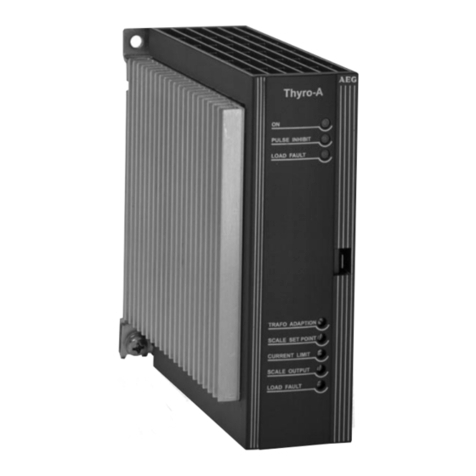
AEG THYRO-A User manual

PERFECT IN FORM AND FUNCTION
Betriebsanleitung/Operating Instructions
Thyristor-Leistungssteller
Thyro-A
Thyristor Power Controller
Thyro-A
Thyro-A

2
Contents
1. General 7
1.1 Type designations/Validity 7
1.2 Abbreviations 10
1.3 Special Features 10
1.4 Warranty 11
2. Safety 12
2.1 Identification in the operating instructions 12
2.2 General danger information 13
2.3 Operator requirements 13
2.4 Personnel requirements 14
2.5 Intended use 14
2.6 Use of the device 15
2.6.1 Operation 15
2.6.2 Prior to installation/commissioning 15
2.6.3 Maintenance, service, faults 16
2.6.4 Transport 17
3. Functions 18
3.1 Operating modes 18
3.1.1 Full wave switch principle TAKT 18
3.1.2 Phase angle principle VAR 19
3.1.3 Half wave switch principle QTM 19
3.2 Setpoint processing 19
3.3 Control modes 20
3.4 Limits 23
3.5 Pulse inhibition 23
3.6 Current and voltage transformer
(only for ...H RL1 and ...H RLP1) 23
3.7 Display via analog output
(only for ...H RL1 and ...H RLP1) 24
3.8 Error and status messages 24
3.8.1 LED messages 29
3.8.2 Fault signalling relay K1
(only for ...H RL1 and ...H RLP1) 31
3.9 Monitoring 32
3.9.1 Monitoring the mains voltage 32

3
EN
3.9.2 Load monitoring (only for ...H RL1 and ...H RLP1) 33
3.9.3 Device temperature monitoring 33
3.9.4 Fan monitoring (for ...F...) 33
3.10 Extended functions
(with bus module / THYRO-TOOL FAMILY) 33
3.10.1 Extended operating modes / circuit types 34
3.10.2 Averaging for the analog output 35
3.10.3 Control limits 35
3.10.4 Controller parameters 35
3.10.5 Mains load optimization 35
4. Settings and operation 36
4.1 Device overview 37
4.2 DIP switches S1 39
4.2.1 Operating mode and load types 41
4.2.2 Control mode / Analog output 41
4.2.3 Live zero and setpoint input range 43
4.2.4 Analog output (only for ...H RL1 and ...H RLP1) 43
4.3 Potentiometer 44
4.3.1 Setting the transformer load (AN1, SST, T0) 45
4.3.2 Setting ohmic load 46
4.3.3 Setting maximum load value with control end U, U2
and P control 47
4.3.4 Setting maximum load current
(only for ...H RL1 and ...H RLP1) 48
4.3.5 Setting example for maximum load value at control
end / maximum load current 49
4.3.6 Adapting analog output (scale)
(only for ...H RL1 and ...H RLP1) 50
4.3.7 Setting load monitoring (undercurrent monitoring)
(only for ...H RL1 and ...H RLP1) 51
5. Installation 58
5.1 Connecting terminals (Overview) 60
5.2 Connecting power supply 62
5.3 Connecting additional electronics supply
(only for ...H RL1 and ...H RLP1) 62
5.4 Connecting pulse inhibition 63

4
5.5 Connecting analog setpoint input 63
5.6 Connecting control input for switch operation 63
5.7 Connecting the bus module 64
5.8 Using the analog output
(only for ...H RL1 and ...H RLP1) 65
5.9 Using the THYRO-TOOL FAMILY 65
6. Mains load optimization 68
6.1 Internal mains load optimization 68
6.2 Synchronization with Thyro-Power Manager 68
6.3 Software synchronization (operating mode TAKT) 69
7. Connecting diagrams 71
8. Help in the event of problems 79
9. Technical data 82
10. Dimension drawings 89
11. Accessories and options 104
12. Approvals and conformity 105

5
EN
List of figures and tables
Fig. 1 Setpoint inputs and effective setpoint 19
Fig. 2 Operating elements 61
Fig. 3 User surface THYRO-TOOL FAMILY 67
Fig. 4 Connection diagram Thyro-A 1A...H1 71
Fig. 5 Connection diagram Thyro-A 2A...H1 72
Fig. 6 Connection diagram Thyro-A 1A ...H RL1, ... H RLP1 73
Fig. 7 Connection diagram Thyro-A 2A ...H RL1, ... H RLP1 74
Fig. 8 Connection diagram Thyro-A 3A...H1 75
Fig. 9 Connection diagram Thyro-A 3A ...H RL1, ... H RLP1 76
Fig. 10 Load connection types 77
Fig. 11 Additional electronics supply and connection with
optional bus module 77
Fig. 12 Connection diagram mains load optimization
with Thyro-Power Manager 78
Fig. 13 Connection diagram mains load optimization
for operating mode TAKT 78
Tab. 1 Effects of a change in the load resistance 22
Tab. 2 Effective limits 23
Tab. 3 Limit values for mains voltage monitoring 32
Tab. 4 Maximum load value at control end 48
Tab. 5 Maximum load current 49
Tab. 6 Analog output (scale) 50
Tab. 7a Load monitoring A 1A/2A, star delta, without neutral 52
Tab. 7b Load monitoring Load with common star point and
without neutral conductor 53
Tab. 7c Load monitoring , A 2A, star point 54
Tab. 8 Load with common star point and without neutral
conductor 55
Tab. 9 Load in delta connection 56
Tab. 10 Other possibilities of load monitoring 57
Tab. 11 Connecting terminals (Overview) 60

6
Contact
Technical queries
Do you have any technical queries regarding the subjects dealt with
in these operating instructions?
If so, please get in touch with our team for power controllers:
Tel. +49(0)2902 763-520 or 763-290
Fax +49(0)2902 763-1201
Commercial queries
Do you have any commercial queries on power controllers?
If so, please get in touch with our team for power controllers.
Tel. +49 (0)2902 763-558 or (02902) 763-591
Service-Hotline
Our team is at your service on the following hotline:
AEG Power Solutions GmbH
Emil-Siepmann-Strase 32
D-59581 Warstein
Tel. +49 (0)2902 763-558 or +49 (0)2902 763-100
http://www.aegps.de
Copyright
No part of these operating instructions may be transmitted, reprodu-
ced and/or copied by any electronic or mechanical means without the
express prior written permission of AEG PS.
© Copyright AEG Power Solutions GmbH 2011.
All rights reserved
Further information on copyright
Thyro-A is an international registered trademark of AEG Power
Solutions GmbH.
Windows and Windows NT are registered trademarks of the Microsoft
Corporation.
All other company and product names are (registered) trademarks of
the respective owners.

7
EN
1. General
The Thyro-A is a communication-capable thyristor power controller.
It can be used wherever alternating voltages, alternating currents or
outputs in thermal process technology need to be controlled. The
Thyro-A has several different control and regulation modes, can
easily be connected to process and automation technology, has a
high degree of control accuracy and is simple to handle.
These operating instructions describe the configuration and functions
of the Thyro-A and are designed to enable qualified personnel to per-
form the following work:
• planning
• commissioning
• maintenance and repair
1.1 Type designations / Validity
These operating instructions describe the Thyro-A series versions
...H 1, H RL1 and ...H RLP1. Product characteristics that are only
provided by the Thyro-A ...H RL1 and ...H RLP1 series are marked
in the text.
These operating instructions comply with the current technical speci-
fications of the device at the time of publication. The contents do not
constitute a subject matter of the contract, but serve for information
purposes only.
We reserve the right to alter any specifications given in these opera-
ting instructions, especially with regard to technical data, operation,
weights and dimensions. AEG PS reserves the right to make modifi-
cations with regard to the content and technical data in these opera-
ting instructions.

8
Type code
The type designation of the thyristor-power controller is derived from
the configuration of the power unit as well as from other features.
Thyro-A 1A Thyristor controller with single phase power unit,
suited for single phase loads
Thyro-A 2A Thyristor controller with two phase power unit, sui-
ted for symmetrical loads in three phase operation
in three phase saver circuit
Thyro-A 3A Thyristor controller with three phase power unit,
suited for three phase loads
Designation Characteristics Different version
(example) of the
power controller
Thyro-A 3A Three phase power controller with three
phase power unit
...400- with 400V type voltage 230V, 400V,
500V, 600V
...280 with 280A type current 16 ... 1500A
H with integrated semiconductor fuse
F with fan (from 280A types) *
R with signalling relay *
L with load monitoring *
P with additional power control
(H RLP) *
1 Identification Thyro-A, series *
Example:
Thyro-A 3A...H1
* device-specific

9
EN
Thyro-A ...H1
Thyristor power controller with integrated semiconductor fuse, sys-
tem bus interface, TAKT and VAR operating modes, synchronization
option (in TAKT operating mode with Thyro-Power Manager option)
and control modes U, U2. Suitable for 3-phase operation in 3-phase
circuit. Suitable for visualization and commissioning software from the
Thyro-Tool Family.
Thyro-A …HRL1
Thyristor power controller with integrated semi conductor fuse, sys-
tem bus interface, additional 24 DC/AC electronic power supply,
signalling relay, load monitoring and analog output, channel separa-
tion, with operating modes TAKT and VAR, synchronization option
(in operating mode TAKT with Thyro-Power Manager), control modes
U, U2, I ,I2. Suitable for the visualization and commissioning software
Thyro-Tool Family.
Thyro-A ...H RLP1
Thyristor power controller with integrated semiconductor fuse, system
bus interface, additional 24 VDC/AC electronic power supply, signal-
ling relay, load monitoring and analog output, channel separation,
with TAKT and VAR operating modes, synchronization option (in ope-
rating mode TAKT with Thyro-Power Manager) and control modes U,
U2, I ,I2and P. Suitable for visualization and commissioning software
Thyro-Tool Family.

10
1.2 Abbreviations
AEG PS AEG Power Solutions GmbH
AN1 Phase angle of the 1st half-wave
SST Soft start time
SYT Synchro cycle
T0Cycle period
TSSwitch-on time
Takt Full wave switch principle - Thyrotakt
Var Phase-angle principle - Thyrovar
QTM Half wave switch principle - Quick takt mode
1.3 Special Features
• Integrated semiconductor fuse
• Type range 230-600V, 16-1500A, single phase, two phase and three
phase
• Additional electronic supply, therefore also operation with mains vol-
tages up to 0.43 x Unom possible (only ...HRL 1 and ...H RLP1)
• Ohmic load and transformer load, as well as load with high
Rwarm /Rcold (≤6) peak current limitation of 3 x Inom (only ...H RL1 and
...H RLP1) in operating mode VAR
• Soft start function for transformer load
• Channel separation, necessary with countervoltage
• Load current monitoring (only ...H RL1 and ...H RLP1)
• Signalling relay (only ...H RL1 and ...H RLP1)
• Analog output (only ...H RL1 and ...H RLP1)
• Control modes U, U2; with ...H RL1 additional I, I2, with ...H RLP1
additional P
• Operating modes TAKT, VAR and QTM (with Thyro-A 1A)
• Synchronization option (for TAKT: with Thyro-Power Manager, for
QTM: with internal mains load optimization)
• Triggering with analog setpoint via PC or optional bus adapter
• System interface standard
• Safe isolation in acc. with EN 50178 ch. 3
• UL approval (for standard devices 16-350A, 495-1500A in prepara-
tion)

11
EN
• Connection for optional visualization and commissioning software
Thyro-Tool Family (via PC-Interface RS232)
Options:
• Connection to various bus systems, e.g. Profibus DPV1, Modbus
RTU) DeviceNet, CANopen, ProfiNet.
Other bus systems on request.
• PC-Interface and THYRO-TOOL FAMILY (visualization and
commissioning software)
1.4 Warranty
In the event of any claims in connection with the Thyro-A, please
contact us quoting:
• type designation
• fabrication number / Serial number
• reason for the complaint
• environmental conditions of the device
• operating mode
• period of use
Goods and services are subject to the general conditions of supply for
products of the electrical industry, and our general sales conditions.
Claims in connection with supplied goods must be submitted within
one week of receipt, along with the delivery note. AEG PS will rescind
all obligations such as warranty agreements, service contracts, etc.
entered into by AEG PS or its representatives without prior notice
if maintenance and repair work is carried out using anything other
than original AEG PS spare parts or spare parts purchased from
AEG PS.

12
2. Safety
2.1 Identification in the operating instructions
In these operating instructions, there are warnings before dangerous ac-
tions. These warnings are divided into the following danger categories:
DANGER
Dangers that can lead to serious injuries or fatal
injuries.
WARNING
Dangers that can lead to serious injuries or considerable
damage to property.
CAUTION
Dangers that can lead to injuries and damage to
property.
CAUTION
Dangers that can lead to minor damage to property.
The warnings can also be supplemented with a special danger sym-
bol (e.g. “Electric current“ or “Hot parts“) , e.g.
risk of electric current or
risk of burns
In addition to the warnings, there is also a general note for useful
information.
NOTE
Content of note

13
EN
2.2 General danger information
DANGER
Electric current
Risk of injury from current carrying parts. There is a danger:
- in the case of devices not controlled, since the load
circuit cannot be disconnected from the power supply
network by the power controller.
- after disconnection from the power supply network,
since the capacitors can still carry a dangerous residual
voltage. Wait approx. 1 minute until the residual voltage
has dissipated
DANGER
Electric current
Risk of injury from current carrying parts.
• Never operate the device without the cover
DANGER
Hot device
Risk of burns from heat sinks and neighbouring plastic
parts
(> 70°C possible)
Do not touch the hot parts of the device.
Affix the “Risk of burns“ warning symbol in the immediate
vicinity of the device.
2.3 Operator requirements
The operator must ensure the following:
• The safety regulations of the operating instructions are observed.
• The accident prevention regulations valid in the respective country
of use and the general safety regulations are observed.
• All safety devices (covers, warning signs etc.) are present, in perfect
condition and are used correctly.
• The national and regional safety regulations are observed.
• The personnel has access to the operating instructions and safety
regulations at all times.

14
• The operating conditions and restrictions resulting from the technical
data are observed.
• Should abnormal voltages, noises, increased temperatures, vibra-
tion or similar occur, the device is immediately put out of operation
and the maintenance personnel is informed.
2.4 Personnel requirements
• Only qualified electro-technical personnel who are familiar with the
pertinent safety and installation regulations may perform the follow-
ing:
- transport
- installation
- connection
- commissioning
- maintenance
- testing
- operation.
• These operating instructions must be read carefully by all persons
working with or on the equipment prior to installation and initial start-
up.
2.5 Intended use
The device may only be used for the purpose for which it was inten-
ded, as persons may otherwise be exposed to dangers (e. g. electric
shock, burns) and plants also (e. g. overload). The user must therefo-
re observe the following points:
• It is not permitted to make any unauthorised modifications to the unit
or to use any spare parts or replacement parts not approved by AEG
PS, or to use the unit for any other purpose.
• The warranty obligations of the manufacturer are only applicable if
these operating instructions are observed and complied with.
• The device may only be used for control and regulation of electrical
power.
• The device is a component that cannot function alone.
• Project planning must account for the proper use of the device.
• Never exceed the maximum permitted connection values as given
on the type plate.

15
EN
• The device may only be operated in conjunction with a connected
ahead mains disconnect device (e. g. switch, VDE 0105 T1).
• It must be guaranteed that in the event of a fault, no uncontrolled
currents, voltages or power may occur in the circuit.
• Despite proper use, it is possible in the event of a fault, that the
device will not control the currents, voltages and power in the load
circuit (example: if the power components are destroyed (broken
down or high-resistance), the following reactions are possible: cur-
rent interrupted, half wave operation, permanent flow of power).
2.6 Use of the device
2.6.1 Operation
• Only switch on the mains voltage at the device when there is no
danger to persons, system or load.
• Protect the device against dust and damp.
• Ensure that the ventilation openings are not blocked
2.6.2 Prior to installation / commissioning
• If stored in a cold environment: ensure that the device is absolutely
dry. (Allow the device a period of at least two hours to acclimatise
before commissioning)
• Check that the voltage data on the type plate matches the mains
voltage.
• Only install the device in an upright position.
• Ensure sufficient ventilation of the cabinet if mounted in a cabinet.
• Observe minimum spacing (clearance: 150 mm above, 100 mm be-
low). The devices can be installed next to each other without spa-
cing between.
• Ensure that the device cannot be heated up by heat sources below
it. (The power loss is given in the type overview table, see page 87,
Technical data).
• Ground the device in accordance with local regulations.
• Connect the device to the mains and the corresponding load in ac-
cordance with the connection diagrams.
• The device is parameterised when delivered. The parameters are
adapted to the particular power unit. (Default: operating mode VAR
without N-conductor). Check default settings and adjust to appli-

16
cation conditions if necessary (e.g. operating mode, control mode,
limitations, monitoring, control characteristic curves, actual value
output, fault messages etc.)
NOTE
Connecting the control signals
The following control signals are absolutely necessary
for operating the devices:
- Setpoint (terminal X2.4 or via bus option)
- Pulse blocking (to ground, on terminal X2.1, X2.2; bridge present)
> Use shielded control conductors to connect the control signals.
If the pulse blocking bridge is not connected, the device is blocked
and is not operating. Communication is still possible via the interface
(see page 63, Connecting pulse blocking).
2.6.3 Maintenance, service, faults
In order to avoid personal and material damages, the user must ob-
serve the following:
• Before all work:
> Disconnect the device from all external voltage sources.
> Secure the device against accidentally being switched back on.
> Use suitable measuring instruments and check that there is no vol-
tage present.
> Ground and short circuit the device.
> Provide protection by covers or barriers for any neighbouring live
parts.
• The device may only be serviced and repaired by trained electro-
technical personnel.
• There is a risk of damage when carrying out repair work on the
power unit.
Various components of the power unit are screwed tight with a pre-
cise torque.
> Repairs to power units have to be carried out by AEG Power
Solutions GmbH!
• see also contact on page 6

17
EN
2.6.4 Transport
• Only transport the device in the original packaging.
• Protect the device against damage, caused by jolts, knocks and
contamination, for instance.

18
3. Functions
In order for the Thyro-A to be adapted as best possible to the required
application, it has numerous functions. These functions are described
in this chapter.
NOTE
Ideal adaption of the Thyro-A to the load
Choose the operating or control mode to adapt the
Thyro-A to best match the load.
NOTE
Times given
The times given (duration), e. g. T0or SST are based
on a 50 Hz mains frequency. With a mains frequency of
60 Hz, the times go down to 5/6 of the indicated value.
3.1 Operating modes
The user selects the operating mode most suitable for optimum ad-
aptation to the various applications and manufacturing processes, as
well as to different electrical loads.
3.1.1 Full wave switch principle TAKT
In this operating mode, the mains voltage is switched periodically,
relative to the defined setpoint. Integer multiples of the mains periods
are switched to avoid d.c. components. The operating mode full wave
switch principle TAKT is particularly suited for loads with thermal iner-
tia. The most important settings for this operating mode are the cycle
time (T0) and the transformer load (see page 45, Setting the transfor-
mer load).
The use of this function achieves the lowest mains feedback. Any
mains feedback that will be still present (e.g. flicker) can be reduced
to an insignificant amount using system load optimization (see page
35, Mains load optimization).

19
EN
3.1.2 Phase angle principle VAR (only A 1A)
In this operating mode, the sinus wave of the mains voltage is shifted.
The shift depends on the setpoint value. Characteristic of this opera-
ting mode are the high control dynamics.
When phase angle control VAR is used, harmonics of the mains
voltage form. These can be compensated for with various types of
circuit.
3.1.3 Half wave switch principle QTM (Quick Takt Mode only 1A)
QTM is the applied for a patent fast operating mode which works on
the half wave switch principle. QTM is suitable for ohmic loads. De-
pending on the predetermined setpoint value, mains half waves are
switched. DC components are avoided for the phase duration.
The fast phase control is particularly suited for IR beams as an
alternative to phase-angle control. When using several controllers it is
possible, by synchronization, to keep the mains feedback small.
3.2 Setpoint processing
Fig. 1:
Setpoint inputs and effective setpoint
The user can adapt the setpoint signal to process controllers or to
the automation system (see page 43, Live zero and setpoint input
range).
refer to chapter 2.6

20
This is done by altering the starting and finishing points of the control
characteristic curve. All common signals can be used.
As soon as the power controller reaches a limit value (Umax, Imax, Pmax),
this is indicated by LEDs (see page 29, LED messages).
The power controller has two setpoint inputs that are electrically isola-
ted from the mains and of which only one is ever active.
• setpoint 1: analog signal X2.4 (+); X2.3 (ground)
• setpoint 2: via system interface (bus module, THYRO-TOOL
FAMILY...)
The effective setpoint is the value when connected through. The set-
point input to be used is defined by configuring terminal X22.1 (see
page 36, Settings and operation).
3.3 Control modes
The power controller has various different control modes.
Before commissioning the power controller and selecting a control
mode, familiarization with the operating procedure and the effect
upon the application is important.
Control modes ...H1
Control mode Control variable
U, U2highest conductor voltage
Control modes ...H RL1
Control mode Control variable
U, U2highest conductor voltage
I, I2 highest phase current
Control modes ...H RLP1
Control mode Control variable
U, U2highest conductor voltage
I, I2highest phase current
P total effective power
Fluctuations in mains voltage and changes in load are compensated
directly by bypassing the inert temperature control circuit. This me-
thod is therefore particularly fast (secondary control).
Other manuals for THYRO-A
1
This manual suits for next models
1
Table of contents
Other AEG Controllers manuals
Popular Controllers manuals by other brands

EMKO
EMKO EDA-3700 instruction manual

Mitsubishi Electric
Mitsubishi Electric RD77GF8 user manual

GSD
GSD GSDn-WEC Installation & user manual

Regin
Regin TTC40FX instructions

Rockwell Automation
Rockwell Automation ics triplex AADvance System Build Manual

Honeywell
Honeywell VC2 Series, VC4 Series, VC60 Series,... quick start guide