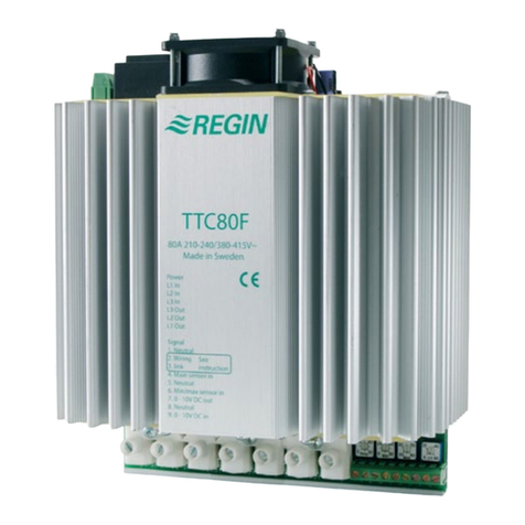
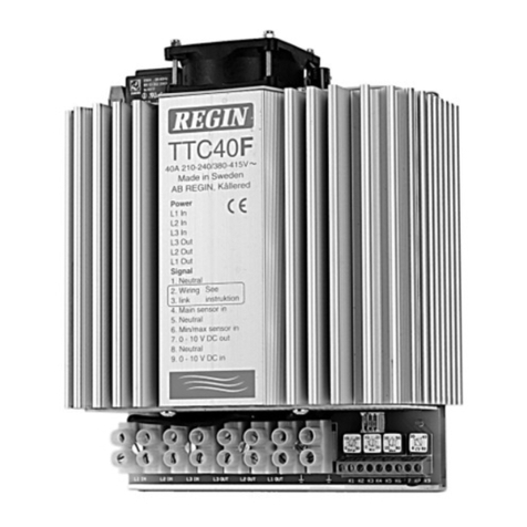
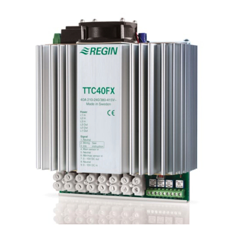
Regin TTC40FX User manual

INSTRUCTION
i
Read this instruction before installation
and wiring of the product
TTC40FX
Consult documentation in all cases where this symbol
is used, in order to nd out the nature of the potential
hazards and any actions to be taken
1
TTC40FX
Triac controller for proportional control
of electric heating
TTC40FX is a proportional controller for electric heating with auto-
matic voltage adjustment. TTC40FX pulses the whole load On - Off.
The ratio between On-time and Off-time is varied 0 - 100% to suit the
prevailing heat demand. The current is always switched at zero phase
angle to prevent RFI.
TTC40FX can control both symmetrical Y-connected 3-phase heaters
and symmetrical or asymmetrical Delta-connected heaters.
TTC40FX is only intended for electric heating control. The control
principle makes it unsuitable for motor- or lighting control. TTC40FX is
intended for DIN-rail mounting.
Installation
Mount TTC40FX on a DIN-rail in a cabinet or other enclosure.
Mount TTC40FX vertically with the text right side up.
Protection class: IP20.
Ambient temperature: 0 - 40°C
N.B. TTC40FX emits approx. 70W of heat at full output which must be
dissipated.
Wiring
Supply voltage
Terminals L1in, L2in and L3in.
Supply voltage: 210-255 or 380-415V AC, 3 phase, 50 - 60 Hz with
automatic voltage adjustment.
Maximum current 40A/phase.
N.B. The supply voltage to TTC40FX should be wired via an all-pole
switch with a minimum contact gap of 3mm.
N.B. TTC40FX must be earthed.
11 3
L1 L2 L3 L3 L2 L1 8 9
Figure 1: Wiring of supply voltage and load
Load
Terminals L1out, L2out and L3out.
Resistive 3-phase heater without neutral
Maximum load: 5290W/phase at 230V phase -
phase voltage (40A).
9200W/phase at 400V phase -
phase voltage (40A).
Minimum load: 530W/phase at 230V phase - phase voltage (4A).
920W/phase at 400V phase - phase voltage (4A).
Settings
CT Cycle time. 6 - 60 seconds.
Control signal
Terminals 8 and 9. Terminal 8 = Signal neutral.
Terminal 9 = 0 - 10V DC. 0V input signal will give 0% output and 10V input
will give 100% output.
Figure 2: Wiring of control signal
NOTE: Do not leave the input unconnected since an open circuit will
not give 0% output but approx. 50%.
To ensure 0% output when no control signal is connected the control
input should be short-circuited.
Control principle
TTC40FX pulses the full load On - Off. TTC40FX adjusts the mean
power output to the prevailing power demand by proportionally adjust-
ing the ratio between On-time and Off-time. The cycle time (=the sum
of On-time and Off-time) is adjustable 0 - 60 seconds.
TTC40FX has zero phase-angle ring to eliminate RFI.
Start-up and fault nding
1. Check that all wiring is correct.
2. Measure the resistance between terminals L1out - L2out, L1out -
L3out and L2out -L3out:
At 230V phase-phase voltage: 6.4Ω<R<64Ω.
At 400V phase-phase voltage: 11.5Ω<R<115Ω.
3. Connect supply voltage and set the input signal to 10V DC. The
LED on the TTC40FX should be continuously on. Set the control
signal to 0V DC. The LED should be continuously off. At inter-mediate
positions the LED will pulse On-Off as the TTC40FX pulses current to
the heater. The pulse cycle period is approx. 6 - 60 seconds depend-
ing on the setting of the CT-potentiometer. Check with a clamp-on
ammeter that current is owing to the heater.
Low Voltage Directive (LVD) standards
This product conforms to the requirements of the European Low
Voltage Directive (LVD) 2006/95/EC through product standard
EN 60730-1.
EMC emissions & immunity standards
This product conforms to the requirements of the EMC Direc-
tive 2004/108/EC through product standards EN 61000-6-1 and
EN 61000-6-3.
RoHS
This product conforms with the Directive 2011/65/EU of the European
Parliament and of the Council.
Contact
AB Regin, Box 116, 428 22 Kållered, Sweden
Tel: +46 31 720 02 00, Fax: +46 31 720 02 50
www.regincontrols.com, [email protected]
1780F
MAR 14
EN

TTC40FX 2
Följ alltid de anvisade säkerhetsföreskrifterna i
dokumentationen för att förebygga risken för brand,
elstöt och personskador
i
Läs denna instruktion innan produkten
monteras och ansluts
INSTRUKTION
TTC40FX
SV
Rumstermostat för styrning av fan-coil-enheter
Triac-regulator för steglös styrning av elvärme
TTC40FX är en steglös trefas effektregulator för elvärmestyrning
med automatisk spänningsanpassning. Regulatorn arbetar steglöst
genom tidsproportionell styrning - Förhållandet mellan tilltid och från-
tid avpassas efter det rådande effektbehovet.
TTC40FX är avsedd att styras av en 0 - 10V DC styrsignal från annan
regulator.
TTC40FX kan användas för styrning av både symmetriska Y-kopp-
lade värmare och symmetriska eller osymmetriska Delta-kopplade
värmare.
TTC40FX är endast avsedd för elvärmestyrning. Reglerprincipen gör
att den inte kan användas till motor- eller belysningsstyrning.
TTC40FX är avsedd för montering på DIN-skena.
Installation
Montera TTC40FX på DIN-skena i apparatskåp eller annan kapsling.
Montera TTC40FX lodrätt med texten rättvänd.
Skyddsform: IP20
Omgivningstemperatur: 0 - 40°C. Icke kondenserande
OBS: TTC40FX avger vid full effekt c:a 70W förlustvärme som måste
kunna kylas bort.
Inkoppling
Matningsspänning (g 1)
Plint L1in, L2in och L3in.
Spänning: 210 - 255 eller 380 - 415V AC 3-fas,
50 - 60 Hz med automatisk spänningsanpassning.
Max ström: 40A/fas.
11 3
L1 L2 L3 L3 L2 L1 8 9
Figur 1: Inkoppling av matningsspänning och belastning
OBS:Matningen till TTC40FX skall ske via en allpolig brytare med
brytavstånd >3mm.
OBS: TTC40FX skall jordas.
Belastning
Plint L1ut, L2ut och L3ut.
Resistiv 3-fas värmare utan nollanslutning.
Max belastning: 5300W/fas vid 230V huvudspänning (40A).
9200W/fas vid 400V huvudspänning (40A).
Min belastning: 530W/fas vid 230V huvudspänning (4A).
920W/fas vid 400V huvudspänning (4A).
Inställningar
CT Pulsperiod. 6 - 60sek.
Styrsignal
Plint 8 och 9.
Plint 8 = Signalnoll.
Plint 9 = 0 - 10V DC in.
0V styrsignal ger 0% utstyrning och 10V ger 100% utstyrning.
Figur 2: Inkoppling av styrsignal
OBS Ingången får inte lämnas öppen (oansluten) då detta inte ger 0%
utstyrning utan c:a 50%.
För att garantera avstängning vid icke ansluten styrsignal skall ingången
kortslutas.
Reglerprincip
TTC40FX pulsar hela den tillkopplade effekten Till-Från. TTC40F
anpassar medeleffekten till det rådande effektbehovet genom att
steglöst anpassa förhållandet mellan Till- och Från-tid.
Pulsperioden (= summan av Till- och Från-tid) är med potentiometern
CT ställbar 6 - 60 sek.
TTC40FX är nollgenomgångsstyrd för att eliminera radiostörningar.
Uppstart
1. Kontrollera att all kablering är riktigt utförd.
2. Mät resistansen mellan plintar L1ut-L2ut, L1ut-L3ut och L2ut-L3ut:
Vid 230V huvudspänning: 6.6Ω<R<66.4Ω.
Vid 400V huvudspänning: 11.5Ω<R<115Ω.
3. Slå på matningsspänningen och sätt styrsignalen till 10V DC.
Lysdioden på TTC40FX skall vara tänd kontinuerligt. Sätt styrsignalen
till 0V DC. Lysdioden skall vara kontinuerligt släckt. I mellanlägen
kommer lysdioden att blinka i takt med att TTC40FX pulsar fram
ström. Pulscykeltiden är 6 - 60 sek beroende på inställningen på CT-
potentiometern .
Kontrollera med tångamperemeter att ström går ut till värmaren då
lysdioden är tänd.
LVD, lågspänningsdirektivet
Produkten uppfyller kraven i det europeiska lågspänningsdirektivet
(LVD) 2006/95/EG genom produktstandard EN 60730-1
EMC emissions- och immunitetsstandard
Produkten uppfyller kraven i EMC-direktivet 2004/108/EG genom
produktstandard EN 61000-6-1 och EN 61000-6-3
RoHS
Produkten uppfyller Europaparlamentets och rådets direktiv 2011/65/
EU
Kontakt
AB Regin, Box 116, 428 22 Kållered, Sverige
Tel: +46 31 720 02 00, Fax: +46 31 720 02 50
www.regin.se, [email protected]

TTC40FX 3
i
Diese Anleitung vor Montage und Anschluss des
Produktes bitte durchlesen
ANLEITUNG
TTC40FX
DE BEACHTE: Lassen Sie den Eingang nicht unangeschlossen da ein
offener Kreis nicht 0% sondern ca. 50% Ausgangssignal liefert. Um
0% Ausgangssignal bei nicht verwendetem Regeleingang zu erzielen
ist der Eingang kurzzuschließen.
Einstellungen
CT Zykluszeit. 6 - 60 Sekunden.
Erststart und Fehlerndung
1. Überprüfen Sie die Verdrahtung und die Funktionsschalter auf kor-
rekte Position.
2. Messen Sie den Widerstand zw. den Klemmen L1out - L2out,
L1out - L3out und L2out -L3out:
Bei 230V Phase-Phase Spannung: 6,4Ω<R<64Ω.
Bei 400V Phase-Phase Spannung: 11,5Ω<R<115Ω.
3. Schließen Sie die Versorgung an und stellen Sie den Sollwert auf
10V, die LED sollte dauernd leuchten. Stellen Sie den Sollwert auf
0V, die LED sollte nicht leuchten. Bei einer speziellen Position des
Sollwertes wird die LED Ein-Auspulsen je nach dem, wie die Leistung
durchgeschalten wird. Die Pulszykluszeit liegt bei ca. 6-60sec. je
nach Einstellung des CT-Potis. Testen Sie mit einem Zangenam-
peremeter ob der Strom auch durch die Last ießt.
Niederspannungsrichtlinie (LVD)
Dieses Produkt entspricht den Anforderungen der Niederspannung-
srichtlinie 2006/95/EG (LVD) durch Erfüllung der Norm EN 60730-1.
Elektromagnetische Verträglichkeit (EMV)
Dieses Produkt entspricht den Anforderungen der EMV-Richtlinie
2004/108/EG durch Erfüllung der Normen EN 61000-6-1 und
EN 61000-6-3.
RoHS
Dieses Produkt entspricht den Anforderungen der Richtlinie 2011/65/
EU des europäischen Parlamentes und des Rates.
Kontakt
RICCIUS + SOHN GmbH Vertriebsbüro Deutschland
Haynauer Str. 49, 12249 Berlin
Tel: +49 30 77 99 40
Fax: +49 30 77 99 413
www.regincontrols.de
Triac-Regler für die stufenlose Steuerung
von Elektrowärme
Der TTC40FX ist ein kompletter stufenloser Leistungsregler für die
Steuerung von Elektrowärme mit autom. Spannungsangleichung der
die gesamte Last mittels Ein-Ausschaltung regelt. Das Verhältnis
zwischen Ein- und Auszeit wird zwischen 0-100% variiert. Der Strom
wird immer im Nulldurchgang geschaltet um RFI zu verhindern.
Der TTC40FX kann symetrische Lasten in Y-Schaltung und asym-
etrische Lasten in Dreieckschaltung steuern. Er darf nur bei Elek-
trowärmern eingesetzt werden, das Steuerungsprinzip lässt keine
Motor- oder Lichtregelung zu. Der TTC 40FX ist zur Hutschienen-
montage gedacht.
Reglerprinzip
Der TTC40FX pulst die Last mittels Ein-Aus-schaltung. Das Verhält-
nis zwischen Ein- und Auszeit wird zwischen 0-100% variiert um ex-
akt dem Heizbedarf angepasst zu werden. Die Zykluszeit (=Summe
der Ein- und Auszeit) wird zwischen 6-60s eingestellt.
Der Strom wird immer im Nulldurchgang geschalten um RFI zu
verhindern.
Einbau
Montieren Sie den TTC40FX auf einer DIN-Schiene in einem
Schaltschrank oder Ähnlichem.
TTC40FX senkrecht mit dem Text richtig herum montieren.
Schutzart: IP20
Umgebungstemperatur: 0-40 °C. Nicht kondensierend
Beachte: TTC40FX gibt bei voller Leistung ca. 70 W Verlustwärme
ab, diese muß abgeführt werden.
Verdrahtung
Versorgungsspannung
Klemmen L1in, L2in und L3in.
Versorgungsspg.: 210-255 oder 380-415V AC 3 Phasen,
50 - 60 Hz mit aut.Spannungs-angleichung.
Maximalstrom 40A/Phase.
11 3
L1 L2 L3 L3 L2 L1 8 9
Abb 1: Anschluß der Versorgungsspannung und Belastung
Beachte: Die Versorgungsspannung sollte über einen allpol. Schütz mit
mind. 3mm Kontaktabstand geschalten werden.
Beachte: Der TTC40FX muß geerdet werden.
Last
Klemmen L1out, L2out und L3out.
Widerstand 3-phasig ohne Nulleiter.
Max. Belastung: 5300W/Phase bei 230V Phase - Phase Spg.
9200W/Phase bei 400V Phase - Phase Spg.
Min. Belastung: 530W/Phase bei 230V Phase - Phase Spg. .
920W/Phase bei 400V Phase - Phase Spg.
Regelsignal
Klemmen 8 und 9.
Klemme 8 = Signal neutral.
Klemme 9 = 0 - 10V DC.
0 V ergibt 0% Ausgang und 10V Eingang ergibt 100% Ausgang.
Abb 2: Anschluß der regelsignal
Dieses Symbol macht auf eventuelle Gefahren bei der
Handhabung des Produkts und der in der Dokumen-
tation nachzulesenden Maßnahmen aufmerksam.

TTC40FX 4
Régulateur à triac pour la commande
progressive de chauffage életrique
TTC40FX est un régulateur triphasé progressif pour le chauffage
électrique, doté d’une adaptation de tension automatique.
Le fonctionnement du régulateur est progressif grâce à une com-
mande chrono-proportionnelle : le temps d’impulsion dépend de la
puissance souhaitée.
TTC40FX doit être commandé par un signal de commande 0 - 10 V
DC d’un autre régulateur.
TTC40FX peut réguler des réchauffeurs symétriques connectés en Y,
ainsi que des réchauffeurs symétriques ou assymétriques connectés
en delta.
TTC40FX est conçu uniquement pour la régulation de chauffage
électrique. Son principe de régulation ne le rend pas adéquat pour la
régulation de moteur ou d’illumination.
TTC40FX est conçu pour montage sur rail DIN.
Installation
Montez le TTC40FX sur rail DIN, dans une armoire ou dans un autre
recouvrement. Monter à la verticale avec le texte à l’endroit.
Indice de protection IP20
Température ambiante 0...40°C non-condensant
N.B. A pleine puissance, le TTC40FX émet environ 70W de chaleur
qui doit être refroidie.
Raccordement
Tension d’alimentation
Bornes L1in, L2in et L3in.
Tension d’alimentation: 210-255 ou 380-412 V AC 3 phases,
50...60 Hz avec adaptation de tension
automatique.
Courant maximal: 40A/phase.
11 3
L1 L2 L3 L3 L2 L1 8 9
Fig 1: Branchement alimentation et batterie
N.B. La tension d’alimentation au TTC40FX doit être raccordée via un
interrupteur omnipolaire avec une distance de coupure d’au moins 3mm.
N.B. TTC40FX doit être mis à la te
Charge
Bornes L1out, L2out et L3out.
Réchauffeur résistif triphasé sans neutre.
Charge max: 5300W/phase à 230V phase, tension de phase (40A)
9200W/phase à 400V phase, tension de phase (40A)
Charge min: 530W/phase à 230V phase, tension de phase (4A)
920W/phase à 400V phase, tension de phase (4A)
Singal de commande
Borne 8 och 9.
Borne 8 = Neutre signal.
Borne 9 = 0 - 10V DC in.
Un signal de commande de 0V correspond à une sortie de 0%, 10V à
100%.
Fig 2: Raccordement du signal de commande
N.B. L’entrée de doit pas être laissée ouverte, comme cela ne correspond
pas une sortie de 0% mais de 50%.
Pour s’assurer que la sortie est à 0% quand un signal de sortie n’est pas
connecté, l’entrée doit être court-circuitée.
Réglages
CT Temps de cycle. 6 - 60sek.
Principe de régulation
TTC40FX pulse toute la puissance connectée. TTC40FX adapte la
puissance moyenne à la demande de puissance actuelle en ajustant
progressivement la longueur des impulsions. Le temps de cycle
(=la somme des temps aux niveaux haut et bas) est ajustable 0...60
secondes avec le potentiomètre. Le TTC40FX a un angle de phase à
zéro pour éviter les perturbations radioélectriques.
Mise en marche
1. Vérier que tout raccordement est fait correctement.
2. Mesurer la résistance entre les bornes L1out-L2out, L1out-L3out
och L2out-L3out:
Pour 230V phase, tension de phase: 6.6Ω<R<66.4Ω.
Pour 400V phase, tension de phase: 11.5Ω<R<115Ω
3. Brancher la tension d’alimentation et mettez le signal de com-
mande à 10 V DC. Le LED du TTC40FX doit s’allumer. Mettez le
signal de commande à 0 V DC. Le LED du TTC40FX doit s’éteindre.
Pour les signaux intermédiaires, le LED clignotera avec le même
rythme que les impulsation de courant du TTC40FX. Le temps de cy-
cle de l’impulsation dépend du réglage du potentiomètre CT, réglable
entre 6...60 secondes. Vériez avec une pince ampèremétrique que
le réchauffeur est alimenté en courant quand le LED est allumé.
Directive basse tension
Ce produit répond aux exigences de la directive 2006/95/CE du
Parlement européen et du Conseil (BT) au travers de la conformité à
la norme EN 60730-1. Il porte le marquage CE.
Directive compatibilité électromagnétique
Ce produit répond aux exigences de la directive 2004/108/CE du
Parlement européen et du Conseil (CEM) au travers de la conformité
aux normes EN 61000-6-1 et EN 61000-6-3.
RoHS
Ce produit répond aux exigences de la directive 2011/65/UE du Parle-
ment européen et du Conseil.
Contact
Regin FRANCE, 32 rue Delizy, 93500 Pantin
Tél : +33(0)1 71 00 34, Fax : +33(0)1 71 46 46
www.regin.fr, [email protected]
INSTRUCTION
i
Veuillez lire cette instruction avant de procéder
à l'installation et au raccordement du produit.
TTC40FX
FR
An d’éviter tout risque d’incident ou d’accident,
veillez à respecter les conseils de sécurité donnés
dans cette notice et identiés par ce symbole.
Table of contents
Languages:
Other Regin Controllers manuals

Regin
Regin RVAN10-24A User manual

Regin
Regin RCF-230AD User manual

Regin
Regin RDAS-24C Series User manual

Regin
Regin Optigo OP5U User manual

Regin
Regin Corrigo U10 Series User manual

Regin
Regin RVAN5-24A User manual

Regin
Regin RDAS18S Series User manual

Regin
Regin RVAR10-230 User manual

Regin
Regin HR1-DH User manual

Regin
Regin PULSER HC-LON User manual

Regin
Regin Corrigo User manual

Regin
Regin RVAZ2-24A User manual

Regin
Regin TTC25X User manual

Regin
Regin XCA152W-4 User manual

Regin
Regin TTC25 User manual

Regin
Regin Optigo OP5U User manual

Regin
Regin RVAN18-24A User manual

Regin
Regin RVAN5-230 User manual

Regin
Regin RVAZ4L1-24 User manual

Regin
Regin PULSER X010 Series User manual