AEG Thyro-E Series User manual

Thyro-E
PERFECT IN FORM AND FUNCTION
Operating Instructions
Thyro-E Lighting Controller, System 3AxxxE (B,T)
Version 2.0 · Last update: 2009-07 · BAL 8000022632, EN

Operations Manual Thyro Power Manager Notes to this Operations Manual
8000022632 BAL, EN Version: 1.7.2009 Page 3 of 3
Operations Manual
Thyro-E; System 3A.xxxE (B,T)
1 Notes to this Operations Manual
1.1 Information Duty
The presented Operations Manual shall carefully be read by all persons deployed for work
using and employing the Thyro-E (hereinafter called the “Unit”) prior to assembly and the
initial start-up of the Unit.
This Operations Manual is a part of the Unit. The operator of the Unit is committed to provide
this Operations Manual to all persons without limitation, who transport the Unit, start it up,
maintain it, or perform other work tasks to it.
1.2 Validity
This Operations Manual resembles the technical status of the Unit at the time of publication.
AEG Power Solutions reserves the right to implement content and technical changes in
comparison to the information of this Operations Manual.
1.3 Loss of Guarantee
Our supplies and services are based on the General Delivery Terms for Products of the
Electro-Technical Industry, as well as on our General Sales Terms. Changes made to the
information of this Operations Manual, especially to technical data, operational instructions,
dimensions and weights, shall remain our reserved right at all times. We request that
complaints regarding delivered products shall be put forward within eight days upon receipt
of the products including the package notes as attached. Claims made later cannot receive
consideration. AEG Power Solutions shall annul all possible obligations, such as guarantee
commitments, service agreements etc., which may be agreed upon by AEG Power Solutions
and its distributors, without prior notice, if purchased spare parts other than OEM AEG Power
Solutions or such other than those purchased via AEG Power Solutions are used for
maintenance and repair.
1.4 Handling
This Operations Manual is structured in a manner so that according expert personnel may
perform all work necessary for commissioning, maintenance, and repair. Certain process
steps are related to figures in order to clarify and to ease necessary work. If threats to
personnel and material cannot be ruled out for certain work, such tasks are marked with a
pictogram, from which the according content for safety regulations may be extracted (see
chapter 3.3).

Notes to this Operations Manual Operations Manual Thyro Power Manager
Page 4 of 4 Version: 1.7.2009 8000022632 BAL, EN
1.5 Conformity
The Unit is designed for presently applicable DIN and VDE regulations in accordance to the
protection class IP 00, and is intended for assembly into according casings or switch
cabinets.
1.6 Manufacturer
AEG Power Solutions GmbH
Emil-Siepmann-Straße 32
D-59581 Warstein-Belecke
1.7 Service
You can receive information about products, availability, prices, as well as about technical
data under the following contact numbers during regular business hours:
Telephone: +49 (0) 2902 763-520 or -290
Telefax: +49 (0) 2902 763-1201
Furthermore, our service is available for you under the following address:
AEG Power Solutions GmbH
Emil-Siepmann-Straße 32
D-59581 Warstein-Belecke
Telefon: +49 (0) 2902 763-100
Fax: +49 (0) 2902 763-680
Internet: www.aegps.de
1.8 Copyright
The forwarding, copying and/or receipt of this Operations Manual via electronical or
mechanical means, even in part, requires the expressive prior and written approval of AEG
Power Solutions.
© Copyright AEG Power Solutions 2009. All rights reserved.

Operations Manual Thyro Power Manager Notes to this Operations Manual
8000022632 BAL, EN Version: 1.7.2009 Page 5 of 5
Table of Contents
1Notes to this Operations Manual..................................................................................... 3
1.1 Information Duty ...................................................................................................... 3
1.2 Validity ..................................................................................................................... 3
1.3 Loss of Guarantee ................................................................................................... 3
1.4 Handling................................................................................................................... 3
1.5 Conformity ............................................................................................................... 4
1.6 Manufacturer............................................................................................................ 4
1.7 Service ..................................................................................................................... 4
1.8 Copyright ................................................................................................................. 4
2General Description ........................................................................................................ 8
3Intended Use................................................................................................................. 10
3.1 Application ............................................................................................................. 10
3.2 Liability ................................................................................................................... 10
3.3 Deployed Symbols ................................................................................................. 10
3.4 Safety Instructions ................................................................................................. 12
3.4.1 Accident Prevention Regulations ..................................................................... 12
3.4.2 General Safety Notes....................................................................................... 12
3.4.3 Fire Protection.................................................................................................. 13
3.4.4 Qualified Personnel.......................................................................................... 14
3.4.5 Safety Conscientious Work Behaviour............................................................. 14
4Installation..................................................................................................................... 15
4.1 Safety Notes .......................................................................................................... 15
4.2 Scope of Delivery, Assembly .................................................................................15
4.2.1 Scope of Delivery............................................................................................. 15
4.2.2 Assembly ......................................................................................................... 15
4.3 Packaging, Storage, Transportation ...................................................................... 16
4.3.1 Packaging ........................................................................................................ 16
4.3.2 Storage ............................................................................................................ 16
4.4 Requirements for Installation ................................................................................. 16
4.4.1 Dimensions / Weights ...................................................................................... 16
4.4.2 General Requirements..................................................................................... 16
4.5 Installation.............................................................................................................. 17
4.5.1 Cooling............................................................................................................. 17
4.5.2 Earthing............................................................................................................ 17
4.5.3 Electric Terminals ............................................................................................ 17
4.5.4 Connection Diagrams ...................................................................................... 19

Notes to this Operations Manual Operations Manual Thyro Power Manager
Page 6 of 6 Version: 1.7.2009 8000022632 BAL, EN
4.5.5 Adaptation to the Lamp Type ...........................................................................22
4.5.6 Adaptation to Local Conditions ........................................................................23
5Shut-Down, Dis-Assembly.............................................................................................24
5.1 Safety Notes...........................................................................................................24
5.2 Electric Terminals...................................................................................................24
5.3 Separation..............................................................................................................24
5.4 Disposal .................................................................................................................24
5.4.1 Legal Regulations ............................................................................................24
5.4.2 Type of Disposal ..............................................................................................24
6Technical Data ..............................................................................................................25
6.1 Type Plate ..............................................................................................................25
6.2 Technical Data .......................................................................................................25
6.3 Dimensions and Weights .......................................................................................27
6.4 Power loss/ efficiency.............................................................................................27
7Functional Description...................................................................................................28
7.1 General ..................................................................................................................28
7.2 Functional Description............................................................................................29
7.2.1 Description of the General Procedures ............................................................30
7.2.2 Control via Internal Timer .................................................................................30
7.2.3 Control via Binary Inputs ..................................................................................31
7.2.4 Pulse Inhibitor ..................................................................................................31
7.3 Messages...............................................................................................................31
7.3.1 Messages with Bypass Contactor ....................................................................32
7.3.2 Default Settings for Messages .........................................................................32
7.3.3 Other Messages...............................................................................................32
7.3.4 Fuse Triggering ................................................................................................32
8Display and Operating Elements...................................................................................32
8.1 Power Controller ....................................................................................................32
8.1.1 Switch S1 .........................................................................................................33
8.1.2 Potentiometer ...................................................................................................33
8.1.3 Analogue Output ..............................................................................................34
8.1.4 LEDs ................................................................................................................34
8.2 Timer ......................................................................................................................36
8.3 Thyro-Tool E ..........................................................................................................37
9Commissioning..............................................................................................................40
9.1 Safety Notes...........................................................................................................40
9.2 Process of Commissioning.....................................................................................40

Operations Manual Thyro Power Manager Notes to this Operations Manual
8000022632 BAL, EN Version: 1.7.2009 Page 7 of 7
9.3 Setting of the Timer ...............................................................................................40
10 Operation ...................................................................................................................... 45
10.1 Regular Operation ................................................................................................. 45
10.2 Service Operation (manually) ................................................................................ 46
10.3 End of Operation.................................................................................................... 46
11 Maintenance ................................................................................................................. 46
11.1 Safety Notes .......................................................................................................... 47
11.2 Maintenance .......................................................................................................... 47
11.2.1 Systems without Integrated Timer ................................................................... 47
11.2.2 Systems with Integrated Timer ........................................................................ 47
11.3 Repairs .................................................................................................................. 48
12 Indexes .........................................................................................................................49
12.1 Figure Indexes ....................................................................................................... 49
12.2 Tables .................................................................................................................... 50
12.3 Index ...................................................................................................................... 50

General Description Operations Manual Thyro Power Manager
Page 8 of 8 Version: 1.7.2009 8000022632 BAL, EN
2 General Description
The Thyro-E System (hereafter called the “system”) is an electronic unit to reduce the output
voltage in three steps. It is designed for the connection of a lighting system to reduce the
operating voltage at certain times and to consequently save costs, energy and CO2. The
system is used for the central supply of several lamps. The system size (or the nominal
current) to be selected principally results from the number and power of the lamps.
The system mainly consists of the following components:
•Autotransformer
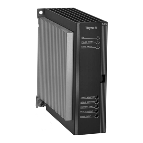
•Power controller type Thyro-A 3A 230-xxx HRLP E
•Timer (“T” for timer)
•Bypass contactor (“B” for bypass) extra, not included in the scope of supply
•Terminals
Thyro-A 3A 230-16 HRLP E Transformer
Figure 1: Thyro-E; System 3A-16 E T
Terminals
Digitaltimer
The system is assembled on an mounting board with complete wiring. The user only has to
provide it between mains supply and lighting system.

Operations Manual Thyro Power Manager General Description
8000022632 BAL, EN Version: 1.7.2009 Page 9 of 9
Figure 2: Circuit without Thyro-E
Figure 3: Circuit with Thyro-E
The system works as a continuous and contactless change-over switch of the transformer
tappings. The continuous and contactless change-over takes place by means of the power
controller Thyro-A 3A 230-xxx HRLP E.
The required stage is selected either by the timer (for systems with “T”) or directly from the
automation system or a building control system of the user through binary inputs.
The output voltage is sinusoidal by a simple through switching of the transformer tappings;
harmonic oscillations are not generated in the mains. Thanks to this characteristic, it is
possible to use either compensated or uncompensated lamps.
Nearly all lamps, even mixed ones, can be used (e.g. sodium vapour lamps (NAV), mercury
discharge lamps (HQL), fluorescent tubes (TL), halogen lamps or simple incandescent
lamps. The lamps can be compensated or uncompensated (cos phi 1 – 0.1).
The transformer tappings selected by the manufacturer (stage 1 = 190V, stage 2 = 205V,
stage 3 = 230V) can be adapted to the local conditions or to the type of lamp by changing
connections. See also chapter 4.5.5 on page 22.
The power controller changes to a higher stage for a variable time after connection to ensure
the normal heating up of the lamps. Afterwards the system switches to the stage selected by
the user.

Intended Use Operations Manual Thyro Power Manager
Page 10 of 10 Version: 1.7.2009 8000022632 BAL, EN
The power controller is provided with an undervoltage monitor. If the mains voltage falls
below this limit, the Unit immediately switches to the next higher stage preventing an
extinguishing of the lamps.
If this limit is reached, the overvoltage monitor, which is also provided in the power
controller ensures the switching to a lower stage. An early deterioration is hereby
counteracted. Certain times, limits, and hystereses can be set in the Thyro-E for a
change-over. However, these parameters are not part of the present Operations
Manual.
Systems marked with the letter “B” are provided with a bypass contactor as bypass
(extra). If the power controller is damaged, the bypass contactor is automatically
switched on and the lighting system continues to work without any failures.
3 Intended Use
3.1 Application
The purpose of this system is the power supply to lighting systems. It is only allowed to be
used for this purpose.
Any other application is an abuse of use, and can endanger persons. Any liabilities of the
manufacturer become void upon abuse of use. The operator and the user of the Unit shall
solely burden the risks for abuse of use.
Intended use includes the observation of the Operations Manual and compliance with
inspection and maintenance intervals. All malfunctions must be remedied immediately,
especially those that impact the safety of the Unit.
3.2 Liability
No liability is burdened for non-intended use of the Unit. The operator and user shall burden
the responsibility for possibly necessary measures for the prevention of people and asset
damage. In case of complaints regarding the Unit, please contact us immediately and include
the following information:
•Type designation
•Fabrication number
•Complaint description
•Duration in operations
•Environmental conditions
•Mode of operation
3.3 Deployed Symbols
The following warning, prohibition, command, and notice symbols are used in the Operations
Manual, around and within the Unit, and at the entrance to the switch room:
Symbol Description

Operations Manual Thyro Power Manager Intended Use
8000022632 BAL, EN Version: 1.7.2009 Page 11 of 11
High Voltage - Danger!
This warning note refers to an especially endangering situation. Upon non-
compliance, death or major injuries may occur due to electric shock. Please
adhere to the described work and process procedures exactly, in order to
avoid damage to people or to the Unit.
Danger!
This warning note refers to an especially endangering situation. Upon non-
compliance, death or major injuries are risked. Please adhere to the
described work and process procedures exactly, in order to avoid damage
to people or to the Unit.
Caution!
This warning note refers to a possibly endangering situation. Upon non-
compliance, minor or medium-level injuries or damage may occur.
Warning about Electro-Magnet Field!
Electrical devices, clocks, magnetic storage cards etc. may malfunction or
be discharged.
Hot Surfaces!
Danger of burning. Prevent touching or wear protection clothes.
Fire Danger!
Smoking or open fire is forbidden.
Access for unauthorized is forbidden!
Access for persons using a cardiac pacemaker is forbidden!
Wear safety shoes!
Information, Note
Notes regarding technical requirements and additional information are
provided here, which the user shall observe.
Table 1: Deployed Symbols

Intended Use Operations Manual Thyro Power Manager
Page 12 of 12 Version: 1.7.2009 8000022632 BAL, EN
3.4 Safety Instructions
3.4.1 Accident Prevention Regulations
Please unconditionally observe the accident prevention regulations of the host country as
deployed within, and the generally valid safety instructions in accordance with IEC 364.
The following 5 safety rules must be complied with, prior to the beginning of all work
performed to the Unit:
Attention High Voltage!!
Safety rules for work performed to electrical facilities:
1. Disconnect equipment from the mains (establish a voltage free status)
2. Secure equipment against re-activation
3. Determine voltage free status of equipment by measurement
4. Earthen and short-circuit equipment
5. Cover or establish borders to neighbouring parts under voltage
3.4.2 General Safety Notes
Important instructions stand out by the use of warning symbols, prohibition symbols,
command symbols, or notice symbols.
The Unit is designed in accordance with state-of-art technology and
accepted technical safety rules.
In spite of this, dangers for the user or third parties and impairments to the
Unit and other assets may unfold in the course of its use.
Poor knowledge about operations and maintenance may create damage to
persons or assets.
Operations and maintenance within the set rule boundaries, as well as
compliance with the following listed safety regulations, are necessary for the
protection of personnel and for the conservation of operational readiness.
Personnel, who assemble, dis-assemble, start-up, operate, and maintain
the Units, must know and observe these safety regulations.
All work may only be performed by expert personnel trained for the task
assigned using those tools, fixtures, inspection means, and materials for
consumption as designed for.
Please observe all legal or otherwise committing regulations for accident
prevention and environmental protection.
Prior to task start-up, personnel assigned for tasks to the Unit must have
read the general and special safety notes, and have sufficiently become
acquainted with the operations of the Unit.

Operations Manual Thyro Power Manager Intended Use
8000022632 BAL, EN Version: 1.7.2009 Page 13 of 13
Please observe all safety and danger notes compiled on the Unit!
All safety and danger notes compiled on the Unit shall be held in full number
and be held a readable status.
No changes, assemblies, and re-fittings, which impact the safety of the Unit,
are allowed to be performed to the Unit without approval of the
manufacturer.
Please secure that only personnel, who are accordingly assigned for work
on the Unit, are deployed.
Third parties shall be held away from the Unit, and also be pointed to the
possible dangers.
Work performed to the Unit may only be performed by an expert electronical
technician or by vocationally trained persons under the management and
peer-overview of an expert electronical technician in accordance with
technical electronical regulations.
The user must install the Unit within a casing or switch cabinet so that no
dangers exist due to touching and that those applicable standards and
safety regulations are complied with.
For all maintenance and repair work, the Unit must be completely de-
activated and secured against unintended re-activation in accordance with
the 5 safety rules (see chapter 3.4.1.).
Existing safety switches are not permitted to be by-passed, de-activated, or
be manipulated in any manner within any operational mode of the Unit
whatsoever.
Only use OEM spare parts!
Personnel must always wear safety shoes during repair and maintenance
work.
Only physically and psychologically healthy staff members are allowed to
work on the Unit.
Personnel under the influence of impairing medication or under the
influence of alcohol are not permitted to work on the Unit.
Table 2: General Safety Notes
3.4.3 Fire Protection
Fire Danger!

Intended Use Operations Manual Thyro Power Manager
Page 14 of 14 Version: 1.7.2009 8000022632 BAL, EN
Fire Danger!
In the case of smoke or smell development, as well as in case of fire, the
Unit shall immediately be switched free of voltage, and a report shall be
made to maintenance personnel. Smoking or open fire is forbidden.
3.4.4 Qualified Personnel
The Unit may only be transported, be assembled, be connected, be started
up, be maintained, and be operated by expert staff members who master
the respectively valid safety and assembly regulations.
Safety regulations shall unconditionally be complied with!
All work performed shall be controlled by responsible expert personnel.
The duly responsible manager for Unit safety with regard to the necessary tasks envisioned
must authorize expert personnel.
Expert personnel are those staff members, who:
•possess the vocational training and experience within the according work area,
•are knowledgeable about the respectively valid legal regulations (laws and codes),
standards, rules, instructions, and accident prevention rules,
•are vocationally trained as to the functional features and operational conditions of the Unit,
•recognize dangers, and are capable of implementing measures in order to prevent
dangers,
Regulations and definitions regarding expert personnel are contained within DIN EN 50110-
1:2004 (DIN EN 50110-1:2004 substitutes DIN 57105-1 and DIN VDE 0105 part 1).
3.4.5 Safety Conscientious Work Behaviour
Qualified personnel as defined in chapter 3.4.4 are responsible for safety. These personnel
are also responsible that only accordingly qualified persons are located at the Unit or within
the safety area.
Observe the following items:
Caution!
Refrain from any kind of working behaviour, which impacts the safety of
persons and the function of the Unit in any form.
Operate the Unit only in a proper condition.
No safety fixtures are allowed to be dis-assembled or be put out of function.
Operationally contingent measures shall be implemented prior to the
removal of safety fixtures for the execution of maintenance and service, or
other work tasks.
Always work in compliance with the 5 technical electrical safety regulations!

Operations Manual Thyro Power Manager Installation
8000022632 BAL, EN Version: 1.7.2009 Page 15 of 15
Safety conscientious work behaviour means that colleagues shall point out
your error behaviour in as far as such is present, and shall report the
determined faults to the relevant department or person.
Table 3: Safety Conscientious Work Behaviour
4 Installation
4.1 Safety Notes
The following 5 safety rules must be complied with prior to the beginning of all work
performed to the Unit:
Attention High Voltage!
Safety rules for work performed to electrical facilities:
1. Disconnect equipment from the mains (establish a voltage free status)
2. Securing against re-activation
3. Determine voltage free status by measurement
4. Earthen and short-circuit equipment
5. Cover or establish borders towards neighbouring parts under voltage
4.2 Scope of Delivery, Assembly
4.2.1 Scope of Delivery
The delivery consists of the following parts for each Thyro-E:
•1 mounting board including:
§autotransformer
§power controller (Thyro-A 3A 230-xxx HRLP E)
§timer
§bypass contactor (extra, only for systems with a „B“)
§terminals
4.2.2 Assembly
The system has to be mounted in a vertical position. In case of assembly into a switch
cabinet, sufficient ventilation and aeration of the cabinet have to be ensured in addition. A
distance of a minimum of 150mm should be maintained above the system to the cabinet or
other assemblies, the clearance below the system should be a minimum of 100mm. It is
possible to mount several systems side by side without observing any lateral distance.
Heating up of the system by heat sources positioned below is to be avoided. The power loss
of the system is indicated in the table „Power loss/ “ on page 27.

Installation Operations Manual Thyro Power Manager
Page 16 of 16 Version: 1.7.2009 8000022632 BAL, EN
Earthing is to be undertaken in accordance with the local regulations!
The system has no own covering. Therefore the user has to ensure a protection against
accidental contact by appropriate measures (installation in a cabinet, closed switch room,
etc.).
4.3 Packaging, Storage, Transportation
4.3.1 Packaging
The equipment is packed for rail or truck transport by the manufacturer.
4.3.2 Storage
The systems may only be stored in dry, ventilated rooms with a firm protective roof in original
packaging for a maximum of six months. It is to be noted that a timer is installed in systems
marked with the letter “T“. This timer is set when being installed in the system and is in
operation afterwards. It runs for approx. 5 years without power supply.
•Permissible ambient temperature: -10°C to +45°C
•Permissible relative air humidity: max. 85%
For longer storage durations, the Units should be contained in airtight plastic skins with the
use of commercially available drying agents.
4.4 Requirements for Installation
4.4.1 Dimensions / Weights
The systems posses the following dimensions and weight:
System Width Height Depth Weight
Thyro-E, System 3A-10 335 mm 330 mm 155 mm 9.9 kg
Thyro-E, System 3A-16 335 mm 330 mm 205 mm 13 kg
Thyro-E, System 3A-30 400 mm 380 mm 225 mm 23 kg
Thyro-E, System 3A-45 400 mm 380 mm 225 mm 32.6 kg
Table 2: Installation / Dimensions and Weights
Consider the following necessary free space upon assembly:
•150 mm upwards
•100 mm downwards
4.4.2 General Requirements
The systems require installation in a vertical position.
Heating up of the systems by heat sources positioned below is to be avoided.

Operations Manual Thyro Power Manager Installation
8000022632 BAL, EN Version: 1.7.2009 Page 17 of 17
The systems may be assembled next to each other without a sideward gap.
The user must install the system within a casing or switch cabinet so that no dangers exist
due to touching and that those applicable standards and safety regulations are complied
with!
4.5 Installation
4.5.1 Cooling
Sufficient ventilation and aeration of the systems has to be ensured so that the maximum
ambient temperature of 45 °C is not exceeded.
4.5.2 Earthing
Earthing shall be performed in accordance with the local regulations! Earthing is also
achieved via EMC facilities (Y – capacitor 4.7nF)
4.5.3 Electric Terminals
The system has to be connected to the mains supply in accordance with the connection
diagrams and the corresponding load (lamps). The following connections are necessary:
•Power supply system: 230V~ to terminal X10
•Connection of the lamp: 230V~ to terminal X20
•Optional: own power supply of the timer: 230V~ to terminal X10
The system is completely parameterized – adapted to the respective system size – and thus
immediately operational upon delivery. The timer is preset, but has to be changed to the
requested time, if necessary.
It may be necessary to reconnect the transformer tappings to adapt to the type of lamp. See
also chapter 4.5.5 „Adaptation to the Lamp Type“ on page 22 and chapter 4.5.6 „Adaptation
to Local Conditions“ on page 23 for this purpose.

Installation Operations Manual Thyro Power Manager
Page 18 of 18 Version: 1.7.2009 8000022632 BAL, EN
Earth connection (to the lamps)
Output L1 / phase to the lamps
Output N / neutral to the lamps
Input N / neutral from the mains
Input (switched) L1 / phase from the mains, for the lamps
Earth connection (from the mains)
Input (permanent) L1 / phase from the mains, for the timer
Figure 4: Terminal block
The following Figure 5 shows the connection of a Thyro-E system with integrated timer. In
this case, the control inputs do not have to be connected. If a permanent supply of 230V~ is
available in the connection range, it can be used for the power supply of the timer. If not, the
connection diagram Figure 6 should be used. If the system is switched off, the power supply
of the timer is ensured by the installed battery.
control inputs

Operations Manual Thyro Power Manager Installation
8000022632 BAL, EN Version: 1.7.2009 Page 19 of 19
4.5.4 Connection Diagrams
Figure 5: Connection Diagram of the Thyro-E (extra supply of the timer)
Figure 6: Connection Diagram of the Thyro-E System 3A-xxx E T

Installation Operations Manual Thyro Power Manager
Page 20 of 20 Version: 1.7.2009 8000022632 BAL, EN
The control has to be carried out by a device provided by the user for systems without
integrated timer. Contacts can be used for this purpose as shown in Figure 7 or voltage
outputs, as shown in Figure 8. See also chapter 9.3 Setting of the Timer.
Figure 7: Connection Diagram of the Thyro-E without timer (control by external contacts)
Figure 8: Connection Diagram of the Thyro- E without timer (control by external outputs)
Three-phase systems can be interconnected from three individual Thyro-E systems. In this
case, only one of the three systems has to be equipped with a timer. Such a three-phase
system would consequently consist of one Thyro-E System 3A-xxx E Tand two Thyro-E
System 3A-xxx E. Besides the respective other phase connection (L1, L2, L3), control
signals have to be interconnected in addition so that one timer can be used by all systems.
See also the following connection diagram for this purpose:

Operations Manual Thyro Power Manager Installation
8000022632 BAL, EN Version: 1.7.2009 Page 21 of 21
Figure 9: Connection Diagram of a Three-Phase Thyro-E System
This manual suits for next models
4
Table of contents
Other AEG Controllers manuals