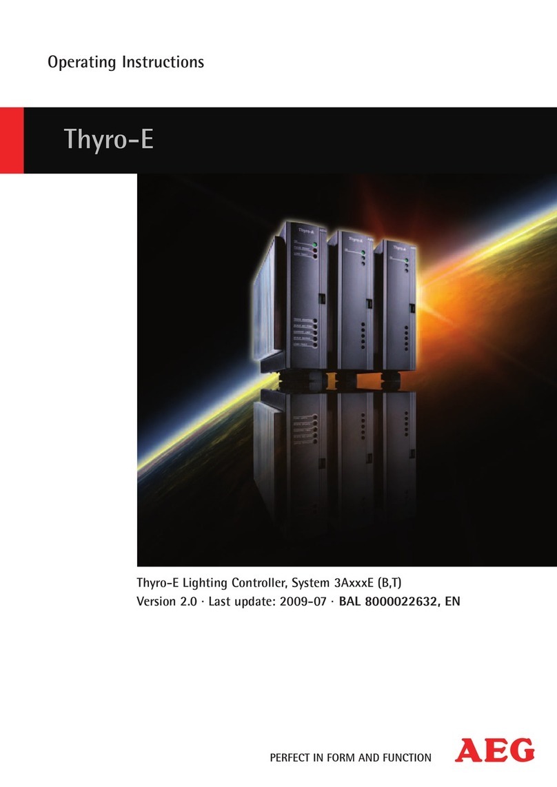
AEG Thyro-Power Manager User manual

Thyro-Power Manager
Version 1.0
Status: 20.06.2008 EL
Operations Manual
Thyro-Power Manager

Notes to This Operations Manual Operations Manual Thyro Power Manager
Page 2 of 52 Version 2008-03-11
Operations Manual
Thyro Power-Manager
1 Notes to This Operations Manual
1.1 Information Duty
The presented Operations Manual shall carefully be read by all persons deployed for work
using and employing the Thyro-Power Manager (hereinafter called the “Unit”) prior to
assembly and the initial start-up of the Unit.
This Operations Manual is a part of the Unit. The operator of the Unit is committed to provide
this Operations Manual to all persons without limitation, who transport the Unit, start it up,
maintain it, or perform other work tasks to it.
1.2 Validity
This Operations Manual resembles the technical status of the Unit at the time of publication.
AEG PSS reserves the right to implement content and technical changes in comparison to
the information of this Operations Manual.
1.3 Loss of Guarantee
Our supplies and services are based on the General Delivery Terms for Products of the
Electro-Technical Industry, as well as on our General Sales Terms. Changes made to the
information of this Operations Manual, especially to technical data, operational instructions,
dimensions and weights, shall remain our reserved right at all times. We request that
complaints regarding delivered products shall be put forward within eight days upon receipt
of the products including the package notes as attached. Claims made later cannot receive
consideration. AEG PSS shall annul all possible obligations, such as guarantee
commitments, service agreements etc., which may be agreed upon by AEG PSS and its
distributors, without prior notice, if purchased spare parts other than OEM AEG PSS or such
other than those purchased via AEG PSS are used for maintenance and repair.
1.4 Handling
This Operations Manual is structured in a manner so that according expert personnel may
perform all work necessary for commissioning, maintenance, and repair. Certain process
steps are related to figures in order to clarify and to ease necessary work. If threats to
personnel and material cannot be ruled out for certain work, such tasks are marked with a
pictogram, from which the according content for safety regulations may be extracted (see
chapter 3.3).

Operations Manual Thyro Power Manager Notes to This Operations Manual
Version 2007-12-05 Page 3 of 52
1.5 Conformity
The Unit is designed for presently applicable DIN and VDE regulations in accordance to the
protection class IP 00, and is intended for assembly into according casings or switch
cabinets.
1.6 Manufacturer
AEG PSS Power Supply Systems GmbH
Emil-Siepmann-Straße 32
D-59581 Warstein
1.7 Service
You can receive information about products, availability, prices, as well as about technical
data under the following contact numbers during regular business hours:
Telephone: + 49 (0) 2902 763-520
Fax: +49 (0) 2902 763-1201
Furthermore, our service is available for you under the following address:
AEG PSS Power Supply Systems GmbH
Emil-Siepmann-Straße 32
D-59581 Warstein
Telephone: +49 (0) 2902 763-100
Internet: www.aegpss.de
1.8 Copyright
The forwarding, copying and/or receipt of this Operations Manual via electronical or
mechanical means, even in part, requires the expressive prior and written approval of AEG
PSS.
© Copyright AEG PSS 2008. All rights reserved.

Notes to This Operations Manual Operations Manual Thyro Power Manager
Page 4 of 52 Version 2008-03-11
Table of Contents
1 Notes to This Operations Manual................................................................................ 2
1.1 Information Duty.................................................................................................... 2
1.2 Validity .................................................................................................................. 2
1.3 Loss of Guarantee................................................................................................. 2
1.4 Handling................................................................................................................ 2
1.5 Conformity............................................................................................................. 3
1.6 Manufacturer......................................................................................................... 3
1.7 Service.................................................................................................................. 3
1.8 Copyright............................................................................................................... 3
2 General Description .................................................................................................... 6
3 Intended Use............................................................................................................... 8
3.1 Application............................................................................................................. 8
3.2 Liability.................................................................................................................. 8
3.3 Deployed Symbols ................................................................................................ 8
3.4 Safety Instructions............................................................................................... 10
3.4.1 Accident Prevention Regulations................................................................... 10
3.4.2 General Safety Notes .................................................................................... 10
3.4.3 Fire Protection............................................................................................... 11
3.4.4 Qualified Personnel....................................................................................... 11
3.4.5 Safety Conscientious Work Behavior............................................................. 12
4 Installation................................................................................................................. 13
4.1 Safety Notes........................................................................................................ 13
4.2 Scope of Delivery, Assembly............................................................................... 13
4.2.1 Scope of Delivery .......................................................................................... 13
4.2.2 Assembly....................................................................................................... 13
4.3 Packaging, Storage, Transportation .................................................................... 14
4.3.1 Packaging...................................................................................................... 14
4.3.2 Storage.......................................................................................................... 14
4.4 Requirements for Installation............................................................................... 14
4.4.1 Dimensions / Weights.................................................................................... 14
4.4.2 General Requirements................................................................................... 14
4.5 Installation........................................................................................................... 15
4.5.1 Cooling.......................................................................................................... 15
4.5.2 Earthing......................................................................................................... 15
4.5.3 Electro Terminals........................................................................................... 15
4.5.4 Connection Diagrams.................................................................................... 16
4.5.4.1Connection for Voltage Supply ...................................................................... 16
4.5.4.2Connection for Network Load Optimization / Power Controller....................... 18
4.5.4.3Connection for Network Peak-Value Monitoring / Measurements .................. 19
4.5.4.4Connection for Analog Outputs...................................................................... 21
4.5.4.5Connection for the Error and Alarm Output.................................................... 22
4.5.4.6Connection for Digital Outputs....................................................................... 22
4.5.4.7Connection of Analog DC Inputs.................................................................... 23
4.5.4.8Connection of Analog AC Inputs.................................................................... 24
5 Shut-Down, Dis-Assembly......................................................................................... 25
5.1 Safety Notes........................................................................................................ 25
5.2 Electro Terminals ................................................................................................ 25
5.3 Separation........................................................................................................... 25
5.4 Disposal .............................................................................................................. 25
5.4.1 Legal Regulations.......................................................................................... 25
5.4.2 Type of Disposal............................................................................................ 25
6 Technical Data.......................................................................................................... 26
6.1 Type Plate........................................................................................................... 26
6.2 Technical Data.................................................................................................... 26

Operations Manual Thyro Power Manager Notes to This Operations Manual
Version 2007-12-05 Page 5 of 52
6.3 Approval and Conformity......................................................................................27
6.4 Dimensions and Weights......................................................................................28
7 Functional Description................................................................................................28
7.1 General Information..............................................................................................28
7.2 Network Load Optimization ..................................................................................28
7.2.1 Automatic Static Network Load Optimization..................................................30
7.2.2 Manual Static Network Load Optimization......................................................32
7.2.3 Reduction of Converter Type Performance via Network Load Optimization....34
7.3 Additional Measurement Device...........................................................................35
7.3.1 ZME Function.................................................................................................36
7.3.2 Monitoring of Network Peak-Load...................................................................37
7.3.3 Voltage Measurement ....................................................................................37
7.3.4 Power and Energy Measurement ...................................................................37
7.3.5 Temperature Measurement............................................................................39
7.3.6 Measurement of Mains Voltage......................................................................39
7.3.7 Measurement of Three Analog Inputs.............................................................39
7.4 I/O Module (Bus / PC)..........................................................................................39
7.5 Messages.............................................................................................................40
7.5.1 Messages at the Error Output.........................................................................40
7.5.2 Messages at the Alarm Output .......................................................................40
7.5.3 Further Messages...........................................................................................40
7.5.4 Fuse Triggering..............................................................................................40
8 Display and Operating Elements................................................................................41
8.1 Switch S1.............................................................................................................41
8.2 Switch S2 - Quantity.............................................................................................42
8.3 Switch S3 – Operating Mode................................................................................43
8.4 Potentiometer R309 .............................................................................................43
8.5 Potentiometer R310 .............................................................................................45
8.6 Analog Outputs ....................................................................................................46
8.7 LEDs....................................................................................................................47
8.8 PC Program .........................................................................................................47
9 Commissioning ..........................................................................................................48
9.1 Safety Notes.........................................................................................................48
9.2 Process of Commissioning...................................................................................48
9.2.1 Setting of the Operating Mode........................................................................48
9.2.2 Setting the Number of Devices Deployed.......................................................48
9.2.3 Setting the Limiting Value for Monitoring ........................................................49
9.2.4 Setting the Elementary Period Duration T
0
.....................................................49
10 Operation...................................................................................................................50
10.1 Regular Operation................................................................................................50
10.2 Service Operation ................................................................................................50
10.3 End of Operation..................................................................................................50
11 Maintenance ..............................................................................................................50
11.1 Repairs.................................................................................................................50
12 Indexes......................................................................................................................51
12.1 Figure Index.........................................................................................................51
12.2 Tables..................................................................................................................52

General Description Operations Manual Thyro Power Manager
Page 6 of 52 Version 2008-03-11
2 General Description
The Thyro Power Manager possesses numerous functions. The Unit can also be deployed
for peak load network monitoring next to its use for network optimization (as a substitute for
the previously deployed SYT9 module). The measuring functions register the effective values
of up to three electrical currents (or voltages), and deliver their effective values as DC signals
(as a substitute for three previously deployed ZME modules). In the course of this, the
integration-time feature is capable for adjustment so that measurements can be made during
full frequency operations. Power and energy consumption may also be measured.
Furthermore, the measurement of mains voltage, temperature, and three DC inputs is
performed. These values may also be displayed. A monitoring function is available for the
most of these measurement values. The Unit possesses a serial interface for the purpose of
PC connection, and an interface to the bus modules of the Thyro family. Thus, the capability
is provided for the query of all measurement values via a PC or bus system. Next to the
easily performed adjustment capability via a switch or potentiometer, the Unit can also be
configured via a comfortable PC program (or via a bus). In the operations mode “I/O
Module”, the analog inputs and outputs, as well as the digital outputs, may be set or read via
a bus (or via a PC). Furthermore, an operations time counter is integrated into the Unit.
Basically, the Unit is composed of the following components:
•Voltage supply 110V /230V
•Automatic frequency recognition
•Terminal to a bus module (Profibus)
•10 Syt-type potential-free terminals
•RS232-PC terminal
•Error and alarm output
•6 analog outputs for 0 -10V
•3 analog inputs, energy levels are
selectable
•3 converter inputs for 1V~ / 100%
•Potentiometers, switches, and LEDs
Figure 1: Block diagram
The Unit is designed for extreme easy operations. Thus, the number of connected power
controllers can directly be adjusted via the rotary switch S2, and the operating mode can
directly be adjusted via the rotary switch S3.

Operations Manual Thyro Power Manager General Description
Version 2007-12-05 Page 7 of 52
In its delivery status, operating mode 1 for “Automatic Static Network Distribution” is set to be
activated (rotary switch S3 = 1). In this application case, the user must then only set the
number of connected power controllers or power controller groups, respectively, via the
rotary switch S2. Further settings are not necessary.
The Unit is designed for assembly to an overhead rail. The connection is implemented via
screw / plug terminals. Voltage supply may selected to either 230V~ or 110V~. The network
frequency is automatically recognized, and all according times are adapted.
Figure 2: Thyro Power Manager with Terminals

Intended Use Operations Manual Thyro Power Manager
Page 8 of 52 Version 2008-03-11
3 Intended Use
3.1 Application
This Unit has the purpose for the network load optimization of power controllers, for use as
measurement map for analog measurement values, and for use as bus I/O module. The Unit
is permitted to be used only for these purposes.
Any other application is an abuse of use, and can endanger persons. Any liabilities of the
manufacturer become void upon abuse of use. The operator and the user of the Unit shall
solely burden the risks for abuse of use.
Intended use includes the observation of the Operations Manual and compliance with
inspection and maintenance intervals. All malfunctions must be remedied immediately,
especially those that impact the safety of the Unit.
3.2 Liability
No liability is burdened for non-intended use of the Unit. The operator and user shall burden
the responsibility for possibly necessary measures for the prevention of people and asset
damage. In case of complaints regarding the Unit, please contact us immediately and include
the following information:
•Type designation
•Fabrication number
•Complaint description
•Duration in operations
•Environmental conditions
•Mode of operation
3.3 Deployed Symbols
The following warning, prohibition, command, and notice symbols are used in the Operations
Manual, around and within the Unit, and at the entrance to the switch room:
Symbol Description
Mains Voltage - Danger!
This warning note refers to an especially endangering situation. Upon non-
compliance, death or major injuries may occur due to electric shock. Please
adhere to the described work and process procedures exactly, in order to
avoid damage to people or to the Unit.

Operations Manual Thyro Power Manager Intended Use
Version 2007-12-05 Page 9 of 52
Danger!
This warning note refers to an especially endangering situation. Upon non-
compliance, death or major injuries are risked. Please adhere to the
described work and process procedures exactly, in order to avoid damage
to people or to the Unit.
Caution!
This warning note refers to a possibly endangering situation. Upon non-
compliance, minor or medium-level injuries or damage may occur.
Warning about Electro-Magnet Field!
Electrical devices, clocks, magnetic storage cards etc. may malfunction or
be uncharged.
Hot Surfaces!
Danger of burning. Prevent touching or wear protection clothes.
Fire Danger!
Smoking or open fire is forbidden.
Access for Unauthorized is Forbidden!
Access for Persons Using a Cardiac Pacemaker is Forbidden!
Wear Safety Shoes!
Information, Note
Notes regarding technical requirements and additional information are
provided here, which the user shall observe.
Table 1: Deployed Symbols

Intended Use Operations Manual Thyro Power Manager
Page 10 of 52 Version 2008-03-11
3.4 Safety Instructions
3.4.1 Accident Prevention Regulations
Please unconditionally observe the accident prevention regulations of the host country as
deployed within, and the generally valid safety instructions in accordance with IEC 364.
The following 5 safety rules must be complied with, prior to the beginning of all work
performed to the Unit:
Attention Mains Voltage!
Safety rules for work performed to electrical facilities:
1. Disconnect equipment from the mains (establish a voltage free status)
2. Secure equipment against re-activation
3. Determine voltage free status of equipment by measurement
4. Earthen and short-circuit equipment
5. Cover or establish borders to neighboring parts under voltage
3.4.2 General Safety Notes
Important instructions stand out by the use of warning symbols, prohibition symbols,
command symbols, or notice symbols.
The Unit is designed in accordance with state-of-art technology and
accepted technical safety rules.
In spite of this, dangers for the user or third parties and impairments to the
Unit and other assets may unfold in the course of its use.
Poor knowledge about operations and maintenance may create damage to
persons or assets.
Operations and maintenance within the set rule boundaries, as well as
compliance with the following listed safety regulations, are necessary for the
protection of personnel and for the conservation of operational readiness.
Personnel, who assemble, dis-assemble, start-up, operate, and maintain
the Units, must know and observe these safety regulations.
All work may only be performed by expert personnel trained for the task
assigned using those tools, fixtures, inspection means, and materials for
consumption as designed for.
Please observe all legal or otherwise committing regulations for accident
prevention and environmental protection.
Prior to task start-up, personnel assigned for tasks to the Unit must have
read the general and special safety notes, and have sufficiently become
acquainted with the operations of the Unit.
Please observe all safety and danger notes compiled on the Unit!
All safety and danger notes compiled on the Unit shall be held in full number
and be held a readable status.
No changes, assemblies, and re-fittings, which impact the safety of the Unit,
are allowed to be performed to the Unit without approval of the
manufacturer.
Please secure that only personnel, who are accordingly assigned for work
on the Unit, are deployed.
Third parties shall be held away from the Unit, and also be pointed to the
possible dangers.

Operations Manual Thyro Power Manager Intended Use
Version 2007-12-05 Page 11 of 52
Work performed to the Unit may only be performed by an expert electronical
technician or by vocationally trained persons under the management and
peer-overview of an expert electronical technician in accordance with
technical electronical regulations.
The user must install the Unit within a casing or switch cabinet so that no
dangers exist due to touching and that those applicable standards and
safety regulations are complied with.
For all maintenance and repair work, the Unit must be completely de-
activated and secured against unintended re-activation in accordance with
the 5 safety rules (see chapter 3.4.1.).
Existing safety switches are not permitted to be by-passed, de-activated, or
be manipulated in any manner within any operational mode of the Unit
whatsoever.
Only use OEM spare parts!
Personnel must always wear safety shoes during repair and maintenance
work.
Only physically and psychologically healthy staff members are allowed to
work on the Unit.
Personnel under the influence of impairing medication or under the
influence of alcohol are not permitted to work on the Unit.
Table 2: General Safety Notes
3.4.3 Fire Protection
Fire Danger!
In the case of smoke or smell development, as well as in case of fire, the
Unit shall immediately be switched free of voltage, and a report shall be
made to maintenance personnel. Smoking or open fire is forbidden.
3.4.4 Qualified Personnel
The Unit may only be transported, be assembled, be connected, be started
up, be maintained, and be operated by expert staff members who master
the respectively valid safety and assembly regulations.
Safety regulations shall unconditionally be complied with!
All work performed shall be controlled by responsible expert personnel.
The duly responsible manager for Unit safety with regard to the necessary tasks envisioned
must authorize expert personnel.
Expert personnel are those staff members, who:
•Possess the vocational training and experience within the according work area,
•Are knowledgeable about the respectively valid legal regulations (laws and codes),
standards, rules, instructions, and accident prevention rules,
•Are vocationally trained as to the functional features and operational conditions of the
Unit,
•Recognize dangers, and are capable of implementing measures in order to prevent
dangers,
Regulations and definitions regarding expert personnel are contained within DIN EN 50110-
1:2004 (DIN EN 50110-1:2004 substitutes DIN 57105-1 and DIN VDE 0105 part 1).

Intended Use Operations Manual Thyro Power Manager
Page 12 of 52 Version 2008-03-11
3.4.5 Safety Conscientious Work Behavior
Qualified personnel as defined in chapter 4.2.6 are responsible for safety. These personnel
are also responsible that only accordingly qualified persons are located at the Unit or within
the safety area.
Observe the following items:
Caution!
Refrain from any kind of working behavior, which impacts the safety of
persons and the function of the Unit in any form.
Operate the Unit only in a proper condition.
No safety fixtures are allowed to be dis-assembled or be put out of function.
Operationally contingent measures shall be implemented prior to the
removal of safety fixtures for the execution of maintenance and service, or
other work tasks.
Always work in compliance with the 5 technical electrical safety regulations!
Safety conscientious work behavior means that colleagues shall point out
your error behavior in as far as such is present, and shall report the
determined faults to the relevant department or person.
Table 3: Safety Conscientious Work Behavior

Operations Manual Thyro Power Manager Installation
Version 2007-12-05 Page 13 of 52
4 Installation
4.1 Safety Notes
The following 5 safety rules must be complied with prior to the beginning of all work
performed to the Unit:
Attention Mains Voltage!
Safety rules for work performed to electrical facilities:
1. Disconnect equipment from the mains (establish a voltage free status)
2. Securing against re-activation
3. Determine voltage free status by measurement
4. Earthen and short-circuit equipment
5. Cover or establish borders towards neighboring parts under voltage
4.2 Scope of Delivery, Assembly
4.2.1 Scope of Delivery
The delivery is comprised of the following parts:
•Thyro Power Manager
•Pouch with screws / plug terminals
•Operations Manual
4.2.2 Assembly
The Units must be assembled on the overhead rail within a switch cabinet / casing. Voltage
supply is performed at terminal X1. In the course, the connection voltage must be selected
there, and the according jumpers must be set (230V~ jumper X1.5 – X1.6; 110V~ jumper
X1.4 –X1.6 and jumper X1.5 – X1.7)
Earthing shall be performed at X1.1 or X1.2 in accordance with local regulations!
For this, see also chapter 4.5.4.1 Connection for Voltage Supply on page 16.

Installation Operations Manual Thyro Power Manager
Page 14 of 52 Version 2008-03-11
4.3 Packaging, Storage, Transportation
4.3.1 Packaging
The Units are packaged within the plant.
4.3.2 Storage
The Unit may be stored in rooms, which are dry, ventilated, and equipped with a fixed
protection roof, and originally OEM packaged.
•Permissible ambient temperature: -25°C to +55°C
•Permissible relative air humidity: max. 85%
For longer storage durations, the Units should be contained in airtight plastic skins with the
use of commercially available drying agents.
4.4 Requirements for Installation
4.4.1 Dimensions / Weights
The Unit possesses the following dimensions and weight:
Unit Width Height
Depth Weight
Thyro Power Manager
150 mm
95 mm
60 mm
0.35 kg
Table 2: Installation / Dimensions and Weights
Consider the following necessary free space upon assembly:
•20 mm upwards
•20 mm downwards
4.4.2 General Requirements
The Units may be assembled next to each other without a sideward gap.
The user must install the Unit within a casing or switch cabinet so that no dangers exist due
to touching and that those applicable standards and safety regulations are complied with!

Operations Manual Thyro Power Manager Installation
Version 2007-12-05 Page 15 of 52
4.5 Installation
4.5.1 Cooling
It shall be observed that the maximum ambient temperature of 55°C is not exceeded.
4.5.2 Earthing
Earthing shall be performed in accordance with the local regulations (terminal X1.1 / X 1.2)!
Earthing is also achieved via EMC facilities (Y – capacitor 4.7nF)
4.5.3 Electro Terminals
The Unit shall only be connected to the voltage supply, and to further external components
(power controllers, measuring transformers), which are contingent to the application.
For this, the following connections are necessary:
•Voltage supply: 110V~ / 230V~ at the terminal X1
•Network load optimization: power controllers at the terminals X3 and X4
•Network peak-load monitoring / measurements:
oUp to 3 converters (1V~) at the terminal X5
oUp to 6 DC outputs (10V-) at the terminals X7 and X8
oError / alarm message at the terminal X8
•I/O module:
oUp to 10 digital outputs at the terminals X3 and X4
oUp to 6 analog outputs (10V-) at the terminals X7 and X8
oUp to 3 analog DC inputs at the terminals X5 and X6
oUp to 3 analog AC inputs at the terminal X5
•PC interface connection: At the terminal X9 (RS232)
•Bus module interface connection: At the terminal X2
As different applications can also be deployed simultaneously, it is necessary to connect the
most various of terminals, in part. E.g., network load optimization (connection of the power
controllers to X3 and X4) and simultaneously network peak-load monitoring (connection of
three electrical current converters to X5) could be deployed, as well as electrical current
measurement (connection of three measurement instruments to X7), and the output of three
analog values (connection of further equipment to X7 and X8). Additionally, three further
analog inputs could be used for reading, and be evaluated via a bus (connection of analog
inputs to X5 and X6, and a bus module connection to X2).

Installation Operations Manual Thyro Power Manager
Page 16 of 52 Version 2008-03-11
An overview of connection opportunities is displayed in the following figure:
Figure 3: Connection Overview
4.5.4 Connection Diagrams
As different connections may be necessary as contingent to the application, the connection
diagrams are illustrated in groups.
4.5.4.1 Connection for Voltage Supply

Operations Manual Thyro Power Manager Installation
Version 2007-12-05 Page 17 of 52
Figure 4: Connection Diagram for Voltage Supply 230V~;50/60 Hz
Figure 5: Connection Diagram for Voltage Supply 110V~; 50/60 Hz

Installation Operations Manual Thyro Power Manager
Page 18 of 52 Version 2008-03-11
4.5.4.2 Connection for Network Load Optimization / Power Controller
The Unit possesses 10 digital outputs at the terminals X3 and X4, in total. These are designed as
potential-free optical coupler outputs. They are deployed as synchronization outputs (SYT) for the
connected Power Controllers or Power Controllers groups during the network load optimization
process. Up to 10 Power Controllers can be connected per channel.
To operate a 2-wire shielded cable is required between Thyro-Power Manager and each Power
Controller.
Figure 6: Connection Diagram for Network Load Optimization Using Thyro-A
Figure 7: Connection Diagram for Network Load Optimization Using Thyro-P

Operations Manual Thyro Power Manager Installation
Version 2007-12-05 Page 19 of 52
4.5.4.3 Connection for Network Peak-Value Monitoring / Measurements
External electrical current converters including load resistances are necessary for network
peak-value monitoring and current measurement. Such must be designed so that a
measurement voltage of 1V~ unfolds as operating at a nominal electrical current (voltage at
the load resistance). These converters must be assembled into the network supply of the
facility for the purpose of network peak-value monitoring. The converter type (for electrical
current or for voltage), as well as their nominal values, should be configured using a PC
program!
Figure 8: Connection Diagram for Network Peak-Load Monitoring / Electrical Current Measurement

Installation Operations Manual Thyro Power Manager
Page 20 of 52 Version 2008-03-11
An external electrical current converter (input 1) and an external voltage converter (input 2)
are needed for (single-phase) power and energy measurement. Input 3 may further be
deployed, additionally. Again, both converters must be configured in a manner so that a 1V~
measurement voltage is generated at a nominal electrical current and at a nominal voltage.
For this reason, the electrical current converter must be equipped with an adequate load
resistance, and possibly, an adequate series resistance must deployed together with the
voltage converter. The internal resistance of the measurement device is 7540 Ohms.
An AEG voltage converter (order no. 2 000 000 399) can be deployed as voltage
transformer. This device possesses a transformer ratio of 16:1, and can primarily be used up
to 690V. If this converter is deployed, the following series resistance values result:
Series Resistance
[Ohm]:
Mains
voltage [V]: Secondary
voltage [V]: Computed:
Selected: Note:
110
6,875
44298
44000
22k + 22k
230
14,375
100848
101000
100k + 1k
400
25
180961
181000
180k + 1k
500
31,25
228087
228200
220k + 8k2
690
43,125
317625
320000
220k + 100k
Table 3: Series Resistance Values for AEG Voltage Converter
Table of contents
Other AEG Controllers manuals
Popular Controllers manuals by other brands

EMKO
EMKO EDA-3700 instruction manual

Mitsubishi Electric
Mitsubishi Electric RD77GF8 user manual

GSD
GSD GSDn-WEC Installation & user manual

Regin
Regin TTC40FX instructions

Rockwell Automation
Rockwell Automation ics triplex AADvance System Build Manual

Honeywell
Honeywell VC2 Series, VC4 Series, VC60 Series,... quick start guide