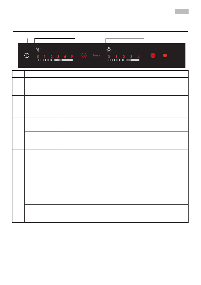
AEG X99384MVO User manual

X99384MVO 3
12
21
30
39
48
57
66
Libretto Istruzioni
User Manual
Mode D'emploi
Bedienungsanleitung
Gebruiksaanwijzing
Manual De Instrucciones
Manual De Instruções
Kullanim Kilavuzu
IT
EN
FR
DE
NL
ES
PT
TR
CAPPA
COOKER HOOD
HOTTE DE CUISINE
DUNSTABZUGSHAUBE
AFZUIGKAP
CAMPANA
EXAUSTOR
OCAK DAVLUMBAZ


PER RISULTATI PERFETTI
Grazie per aver scelto di acquistare questo prodotto AEG. Lo
abbiamo creato per fornirvi prestazioni impeccabili per molti
anni, grazie a tecnologie innovative che vi semplificheranno
la vita - funzioni che non troverete sui normali elettrodo-
mestici. Vi invitiamo di dedicare qualche minuto alla lettura
per sapere come trarre il massimo dal vostro elettrodomesti-
co.
ACCESSORI E PRODOTTI DI CONSUMO
All'interno del webshop AEG troverete tutto ciò che vi ser-
ve per fare in modo che i vostri elettrodomestici AEG siano
sempre perfettamente puliti e funzionanti. Non mancano
inoltre una vasta gamma di accessori studiati e realizzati
conformemente agli elevati standard qualitativi che vi aspet-
tate: pentole, scolaposate, portabottiglie e sacchi biancheria
delicati...
Visit the webshop at:
www.aeg-electrolux.com/shop

IT - CONSIGLI E SUGGERIMENTI/CARATTERISTICHE
4
IT - CONSIGLI E SUGGERIMENTI - Questo libretto di istruzioni per l'uso è previsto per più versioni dell' apparecchio. É possibile che siano descritti singoli
particolari della dotazione, che non riguardano il Vostro apparecchio. Il produttore declina qualsiasi responsabilità per danni dovuti ad installazione non corretta
o non conforme alle regole dell’arte. La distanza minima di sicurezza tra il Piano di cottura e la Cappa deve essere di 650 mm. Vericare che la tensione di rete
corrisponda a quella riportata nella targhetta posta all’interno della Cappa. Per Apparecchi in Classe Iaaccertarsi che l’impianto elettrico domestico garantisca un
corretto scarico a terra. Collegare la Cappa all’uscita dell’aria aspirata con tubazione di diametro pari o superiore a 120 mm. Il percorso della tubazione deve essere
il più breve possibile. Non collegare la Cappa a condotti di scarico dei fumi prodotti da combustione (caldaie, caminetti, ecc.). Nel caso in cui nella stanza vengano
utilizzati sia la Cappa che apparecchi non azionati da energia elettrica (ad esempio apparecchi utilizzatori di gas), si deve provvedere ad una aerazione sufciente
dell’ambiente. Se la cucina ne fosse sprovvista, praticare un’apertura che comunichi con l’esterno, per garantire il richiamo d’aria pulita. La Cappa è stata progettata
esclusivamente per uso domestico, per abbattere gli odori della cucina. Non fare mai uso improprio della Cappa. Non lasciare amme libere a forte intensità sotto la
Cappa in funzione. Regolare sempre le amme in modo da evitare una evidente fuoriuscita laterale delle stesse rispetto al fondo delle pentole. Controllare le friggitrici
durante l’uso: l’olio surriscaldato potrebbe inammarsi. Non preparare alimenti ambè sotto la cappa da cucina; pericolo d'incendio. Questo apparecchio non deve
essere utilizzato da persone (bambini inclusi) con ridotte capacità psichiche, sensoriali o mentali, oppure da persone senza esperienza e conoscenza, a meno che
non siano controllati o istruiti all’uso dell’apparecchio da persone responsabili della loro sicurezza. I bambini devono essere supervisionati per assicurarsi che non
giochino con l’apparecchio. Prima di procedere a qualsiasi operazione di manutenzione, disinserire la Cappa togliendo la spina elettrica o spegnendo l’interruttore
generale. Effettuare una scrupolosa e tempestiva manutenzione dei Filtri secondo gli intervalli consigliati (Rischio di incendio), Filtri antigrasso Z Sono lavabili anche
in lavastoviglie, e necessitano di essere lavati ogni 2 mesi circa di utilizzo o più frequentemente, per un uso particolarmente intenso - Filtri antiodore al Carbone attivo
WIl Filtro antiodore al Carbone attivo non è lavabile e non è rigenerabile, va sostituito ogni 4 mesi circa di utilizzo o più frequentemente, per un uso particolarmente
intenso. Per la pulizia delle superci della Cappa è sufciente utilizzare un panno umido e detersivo liquido neutro. Il simbolo sul prodotto o sulla confezione
indica che il prodotto non deve essere considerato come un normale riuto domestico, ma deve essere portato nel punto di raccolta appropriato per il riciclaggio di
apparecchiature elettriche ed elettroniche. Provvedendo a smaltire questo prodotto in modo appropriato, si contribuisce a evitare potenziali conseguenze negative
per l’ambiente e per la salute, che potrebbero derivare da uno smaltimento inadeguato del prodotto. Per informazioni più dettagliate sul riciclaggio di questo prodotto,
contattare l’ufcio comunale, il servizio locale di smaltimento riuti o il negozio in cui è stato acquistato il prodotto.
Collegare la Cappa all’Alimentazione di Rete interponendo un Interruttore bipolare con apertura dei contatti di almeno 3 mm.
Attenzione: Prima di installare la Cappa, togliere le pellicole di protezione (bianca e trasparente).
CARATTERISTICHE
Ingombro

IT - CONSIGLI E SUGGERIMENTI/CARATTERISTICHE 5
Componenti
Rif.Q.tà Componenti di Prodotto
1 1 Corpo Cappa completo di: Comandi,
Luce, Gruppo Ventilatore, Filtri
8 1 Griglia direzionata Uscita Aria
9 1 Flangia di Riduzione ø 150-120 mm
10 1 Flangia ø 150 con valvola di non ri-
torno
16 1 Coperchio filtrante
Rif.Q.tà Componenti di Installazione
11 2 Tasselli
11a 2 Tasselli SB 12/10
12a 2 Viti 4,2 x 44,4
12c 4 Viti 2,9 x 6,5
12d 2 Viti 2,9 x 9,5
Q.tà Documentazione
1 Libretto Istruzioni
�

IT - INSTALLAZIONE
6
INSTALLAZIONE
Foratura Parete e Fissaggio Staffe
Tracciare sulla Parete:
• unalineaVerticalefinoalsoffittooallimitesuperiore,alcentrodellazonaprevistaperil
montaggio della Cappa;
• unalineaOrizzontalea1004mmmin.soprailPianodiCottura.
• Segnareunpunto(1) sulla linea orizzontale a 247 mm alla destra della linea verticale di rife-
rimento.
• Ripeterequestaoperazionedallaparteopposta,verificandoneillivellamento.
• Segnarecomeindicato,unpuntodiriferimento(2) a 210 mm dalla linea Verticale di riferi-
mento, e 482 mm sopra il Piano di Cottura.
• Ripeterequestaoperazionedallaparteopposta,verificandoneillivellamento.
• Forareø12mmipunti(1) segnati.
• Forareø8mmipunti(2) segnati.
• Inserireitasselliconstaffa11aneifori(1) e avvitare.
• Inserireiltassello11neifori(2).
Per installazione con camino decorativo: (Opzionale)
• AppoggiarecomeindicatolaStaffa7.2.1 a 1-2 mm dal soffitto o dal limite superiore, alline-
andoilsuocentro(intagli)sullalineaVerticalediriferimento.
• SegnareicentrideiForidellaStaffa.
• AppoggiarecomeindicatolaStaffa7.2.1 aXmmsottolaprimastaffa(X=altezzaCamino
Superioreindotazione),allineandoilsuocentro(intagli)sullalineaVerticalediriferimento.
• SegnareicentrideiForidellaStaffa.
• Forareø8mmipuntisegnati.
• Inserireitasselli11 nei fori.
• FissareleStaffeutilizzandoleViti12a(4,2x44,4)indotazione.

IT - INSTALLAZIONE 7
MONTAGGIO CORPO CAPPA
• Aprire il pannello aspirante superiore e bloccarlo
sulla sinistra con l’astina al corpo Cappa affinché
non si richiuda.
• Sbloccaretogliendoilpernodifissaggiosullasinistra
il pannello aspirante inferiore ed aprirlo.
• Togliere i Filtri Antigrasso agendo sulle apposite
maniglie.
• RegolareleduevitiVr, delle staffe 11a, ad inizio
corsa.
• Agganciareilcorpocappaalle2staffe11a.
• Dall’internodelcorpocappaagiresulleVitiVr per
livellare il Corpo Cappa.
• Avvitarelevitidisicurezza 11.
• Richiudereipannelliaspiranti.
CONNESSIONI
USCITA ARIA VERSIONE ASPIRANTE
Per installazione in Versione Aspirante collegare la
Cappa alla tubazione di uscita per mezzo di un tubo
rigidooflessibile diø150o 120mm,la cuisceltaè
la-sciata all'installatore.
Collegamento tubo ø 150
• Inserire la Flangia ø 150 10 sull’Uscita del Corpo
Cappa.
• Fissare il tubo con adeguate fascette stringitubo.
Ilmaterialeoccorrentenonèindotazione.
Collegamento tubo ø 120
• Per collegamento con tubo ø120 mm, inserire
la Flangia di riduzione 9 sulla flangia ø 150 10
prece-dentemente installata.
• Fissare il tubo con adeguate fascette stringitubo.
Ilmateriale occorrentenonèindotazione.
• Inambedueicasi,togliereeventualiFiltriAntiodore
al Carbone attivo.
USCITA ARIA VERSIONE FILTRANTE
PerinstallazioneinVersioneFiltranteènecessarioac-
quistare il kit opzionale Cartuccia al carbone attivo.
• Avvitare il coperchio filtrante sull’uscita aria, uti-
lizzando quattro viti 12c(2,9x6,5).
• Fissare la Griglia direzionata 8sull’uscita dell’aria
riciclata con 2 Viti 12d(2,9 x9,5)indotazione.

IT - INSTALLAZIONE
8
CONNESSIONE ELETTRICA
• CollegarelaCappaall’Alimentazionedi Rete
interponendo un Interruttore bipolare con
apertura dei contatti di almeno 3 mm.
• RimuovereiFiltriantigrasso(vedipar.“Ma-
nutenzione”) e assicurarsi che il connettore
del Cavo di alimentazione sia correttamente
inserito nella presa dell’Aspiratore

IT - USO 9
Tasto Funzione Specifiche
AOn/Off Funzioni Cappa Toccandoil tasto a Cappaspenta si illuminano (intensità 50%) e vengono abilitate tutte
le funzioni.
Toccandoil tasto a Cappafunzionante spegne disabilitando tutte le funzioni (Motore
Off + Luci Off).
BGestisce Velocità
motore:
0-V1-V2-V3-V4-P
Toccandol’areasiattivailmotoreallavelocitàdesiderata.
P=Velocità Intensiva, temporizzata a 5 minuti, al terminedel tempo il sistema ritorna
allaprecedentevelocità, seattivata da MotoreOffpassaaV1.
Altoccodellavelocitàdesiderata,questasiillumineràmaggiormente(intensità100%)
rispettoallealtrefunzioni(intensità50%).
CFunzione Delay Toccando il tasto si attiva lo spegnimento automatico ritardato del Motore e dell’Im-
piantodiIlluminazionedi10 minuti. Attivabile solo da motore acceso, velocità non
IntensivaeSensor=Off.
Attiva / Disattiva il
ricevitore del Teleco-
mando.
Toccandoil Tastoper4secondi(MotoreOff+LuciOff),inassenzadialtriallarmi,il
Led lampeggia per:
4 secondi indicando l’Attivazione del Telecomando
2 secondi indicando la Disattivazione del Telecomando
DSensor Inquesta modalità laCappa funziona in modo automatico per un massimo di 5ore,al
termine la funzione spegne il motore.
Lacappamodificalavelocitàdelmotoreinbaseaquantopercepitodal Sensore.
I Tasti B e C non funzionano, si disattiva premendo il tasto o spegnendo la Cappa.
EGestisce Intensità Luce:
0-L1-L2-L3-LMax Toccandol’areasiaccendonoleLuciall’Intensitàdesiderata.Altoccodell’Intensità
Lucedesiderata,questa siilluminerà maggiormente (intensità 100%)rispettoallealtre
funzioni(intensità50%).
FReset FiltriEffettua
il Reset dell’allarme
saturazione Filtri Toc-
cando il tasto a Motore
Spento.
Dopo100 orediFunzionamentoilLedèAccesoFissopersegnalarelasaturazionedei
Filtri Metallici.
Dopo 200 ore di Funzionamento il Led Lampeggia per segnalare la saturazione dei Filtri
al Carbone Attivo.
Attiva / Disattiva allar-
me saturazione Filtri al
Carbone Attivo.
Toccandoil Tastoper4secondi(MotoreOff+LuciOff),inassenzadialtriallarmi,il
Led lampeggia per:
4 secondi indicando l’Attivazione Allarmi Filtri al Carbone
2 secondi indicando la Disattivazione Allarmi Filtri al Carbone
USO
A B C D E F
Dopo aver collegato la cappa alla rete elettrica, i comandi saranno abilitati dopo circa 4 secondi. In tale periodo lampeggia il led "0" del
tastomotore.ACappaspentanessunafunzioneèvisualizzata,èvisibilesololaparteinchiarodelpannellocomandi.Tuttoilrestos’illumi-
nerà(intensità50%)toccandoilTastoA.
IComandis’attivanocoltoccodellafunzionesceltaches’illumineràmaggiormente(intensità100%)rispettoallealtrefunzionidellaCap-
pa(intensità50%).Dopo10secondidiassenzacomandi,rimarrannoaccesesololefunzioniselezionate(Intensità100%)spegnendotutto
ilresto(Intensità50%).Dopo7orediusoinassenzadicomandilaCappasispegne(MotoreOff+LuciOff),daquestasituazioneconun
toccosiriabilitanolefunzioni,alsuccessivoèpossibileselezionarelafunzionedesiderata.
ÈpossibileattivareunafunzionedellaCappa(VelocitàeLuce),nonsolotoccandoilquadrocomandimaancheappoggiandociilditoe
scorrendo verso la funzione scelta senza alzarlo.
Sevienecomandatolospegnimentodimotoreeluci,portandoliazero,rimangonoaccesial50%tuttiileddeicomandiesenoncisono
altricomandineisuccessivi10sec,tuttiledverrannospentiadeccezionedeiled“0”,cherimarrannoonperaltri15minuti.

IT - OPZIONI CAPPA MODALITÀ SENSOR/ILLUMINAZIONE
10
OPZIONI CAPPA MODALITÀ SENSOR
Nelfunzionamento inmodalitàSensor
influisce il tipo di piano utilizzato, sono
stateprevisteduepossibilità:
• Pianoelettrico;
• Pianoa gas;
Inizialmenteèselezionatoilpianoelet-
trico,per cambiareènecessarioseguire
la seguente procedura:
• Spegnerelacappaconiltastoon/off
cappa
• Tenerepremuto iltastoSensor per 8
secondi fino al lampeggio del led:
• 4lampeggiindicanolaselezione
del piano elettrico;
• 2lampeggiperilpianoagas;
• Toglierel’alimentazioneper10secondi
e poi ricollegarla.
Ogni volta che viene cambiato il tipo
di piano, viene eseguita la procedura di
calibrazione.
Procedura di calibrazione: ogni volta
che la cappa viene alimentata o viene
cambiato il piano cottura si attiva la
procedura di calibrazione del sensore,
durante la quale la cappa non deve
essere esposta a processi di cottura o in-
vestita da odori particolarmente intensi,
tipo solventi o detergenti.
Tale processo prevede un tempo di:
• 13minseèselezionatoilpianoelet-
trico;
• 1minseèselezionatoilpianoagas;
Questafase èsegnalatadallampeg-
giodel leddeltastosensorseèstato
premuto.Durante la calibrazione non
accendere il motore.
ILLUMINAZIONE
Attenzione: Questo apparecchio è provvisto di
una luce LED bianca di classe 1M secondo la
norma EN 60825-1: 1994 + A1:2002 + A2:2001;
massima potenza ottica emessa@439nm: 7µW.
Non osservare direttamente con strumenti ottici
(binocolo,lente d’ingrandimento….).
•Per la sostituzione contattare l’Assistenza
Tecnica.("Perl'acquistorivolgersiall'assistenza
tecnica").
Attenzione: non spruzzare direttamente
sulla griglia i prodotti di pulizia ma di pulirla
unicamente con panni imbevuti di detergen-
te. Evitare per la pulizia della griglia prodotti
alcolici o siliconici.

FOR PERFECT RESULTS
Thank you for choosing this AEG product. We have created
it to give you impeccable performance for many years, with
innovative technologies that help make life simpler – fea-
tures you might not find on ordinary appliances. Please
spend a few minutes reading to get the very best from it.
ACCESSORIES AND CONSUMABLES
In the AEG webshop, you’ll find everything you need to keep
all your AEG appliances looking spotless and working per-
fectly. Along with a wide range of accessories designed and
built to the high quality standards you would expect, from
specialist cookware to cutlery baskets, from bottle holders to
delicatelaundrybags…
Visit the webshop at:
www.aeg-electrolux.com/shop

EN - RECOMMENDATIONS AND SUGGESTIONS/CHARACTERISTICS
12
EN - RECOMMENDATIONS AND SUGGESTIONS - The Instructions for Use apply to several versions of this appliance. Accordingly, you may nd descrip-
tions of individual features that do not apply to your specic appliance. The manufacturer will not be held liable for any damages resulting from incorrect or improper
installation. The minimum safety distance between the cooker top and the extractor hood is 650 mm. Check that the mains voltage corresponds to that indicated on
the rating plate xed to the inside of the hood. For Class I appliances, check that the domestic power supply guarantees adequate earthing. Connect the extractor to
the exhaust ue through a pipe of minimum diameter 120 mm. The route of the ue must be as short as possible. Do not connect the extractor hood to exhaust ducts
carrying combustion fumes (boilers, replaces, etc.). If the extractor is used in conjunction with non electrical appliances (e.g. gas burning appliances), a sufcient
degree of aeration must be guaranteed in the room in order to prevent the backow of exhaust gas. The kitchen must have an opening communicating directly with
the open air in order to guarantee the entry of clean air. The extractor hood has been designed exclusively for domestic use to eliminate kitchen smells. Never use
the hood for purposes other than for which it has been designed. Never leave high naked ames under the hood when it is in operation. Adjust the ame intensity
to direct it onto the bottom of the pan only, making sure that it does not engulf the sides. Deep fat fryers must be continuously monitored during use: overheated oil
can burst into ames. Do not ambè under the range hood; risk of re This appliance is not intended for use by persons (including children) with reduced physical,
sensory or mental capabilities, or lack of experience and knowledge, unless they have been given supervision or instruction concerning use of the appliance by a
person responsible for their safety. Children should be supervised to ensure that they do not play with the appliance. Switch off or unplug the appliance from the
mains supply before carrying out any maintenance work.Clean and/or replace the Filters after the specied time period (Fire hazard), Grease lters Z The lters must
be cleaned every 2 months of operation, or more frequently for particularly heavy usage, and can be washed in a dishwasher. - Activated charcoal lter WThese
lters are not washable and cannot be regenerated, and must be replaced approximately every 4 months of operation, or more frequently with heavy usage. Clean the
hood using a damp cloth and a neutral liquid detergent. The symbol on the product or on its packaging indicates that this product may not be treated as household
waste. Instead it shall be handed over to the applicable collection point for the recycling of electrical and electronic equipment. By ensuring this product is disposed
of correctly, you will help prevent potential negative consequences for the environment and human health, which could otherwise be caused by inappropriate waste
handling of this product. For more detailed information about recycling of this product, please contact your local city ofce, your household waste disposal service or
the shop where you purchased the product.
Connect the hood to the mains through a two-pole switch having a contact gap of at least 3 mm.
Warning: Before installing the Hood, remove the protective lms (white and transparent).
CHARACTERISTICS
Dimensions

EN - RECOMMENDATIONS AND SUGGESTIONS/CHARACTERISTICS 13
Components
Ref.Q.ty Product Components
1 1 Hood Body, complete with: Controls,
Light, Blower, Filters
81 Directional Air Outlet grille
9 1 ReducerFlangeø150-120mm
10 1 Dumper
16 1 Filter cover
Ref.Q.ty Installation Components
11 2 Wall Plugs
11a 2 Wall Plugs SB 12/10
12a 2 Screws 4,2 x 44,4
12c 4 Screws 2,9 x 6,5
12d 2 Screws 2,9 x 9,5
Q.ty Documentation
1 Instruction Manual
�

EN - INSTALLATION
14
INSTALLATION
Wall drilling and bracket fixing
As a first step, proceed with the following drawings:
• averticallineuptotheceilingoruptotheupperlimit,atthecentreoftheareainwhichthe
hood is to be fitted;
• ahorizontallineataminimum1004mmabovethecookertop.
• Markapoint(1) on the horizontal line, 247 mm to the right of the vertical reference line.
• Repeatthisoperationontheotherside,checkingthatthetwomarksarelevelled.
• Markareferencepoint(2) as indicated at 210 mm from the vertical reference line and 482
mm above the cooker top.
• Repeatthisoperationontheotherside,checkingthatthetwomarksarelevelled.
• Drillatthemarkedpoints(1),usingaø12mmdrillbit.
• Drillatthemarkedpoints(2)usingaø8mmdrillbit.
• Insertthebracketplugs11aintotheholes(1) and tighten the screws.
• Insertplug11intoholes(2).
To install a decorative chimney ( optional )
• Placebracket7.2.1 on the wall, about 1-2 mm from the ceiling or from the upper limit,
aligningthecentre(notch)withtheverticalreferenceline.
• Markthewallatthecentresofthebracketholes.
• Placethebracket7.2.1onthewallatXmmbelowthefirstbracket(X=heightoftheupper
chimneysection),aligningthecentre(notch)withtheverticalline.
• Markthewallatthecentresofthebracketholes.
• Drillø8mmholesatallthemarkedcentrepoints.
• Insertthewallplugs11 in the holes.
• Fixthebracketsusingthe12ascrews(4,2x44,4)suppliedwiththehood.

EN - INSTALLATION 15
FITTING THE HOOD BODY
• Open the top suction panel and fasten it to the
hood body on the left using the pin, so that it
does not close again.
• Unlock the lower suction panel by removing the
fixing pin on the left, and open it.
• RemovetheMetalgreasefiltersusingthehandles
provided.
• AdjustthetwoscrewsVr, in the brackets 11a, so
that they are at the start of their travel.
• Hookthe hoodbodytothetwobrackets11a.
• Fromtheinsideofthehoodbody,turnscrewsVr
to level the hood body itself.
• Fastenthe safetyscrews11.
• Closethe suctionpanels.
CONNECTIONS
DUCTED VERSION AIR EXHAUST SYSTEM
When installing the ducted version, connect the hood
to the chimney using either a flexible or rigid pipe
ø150or 120mm,thechoice ofwhichis lefttothe
installer.
To install a ø 150 pipe
• Toinstallthedumper10
• Fixthepipeinpositionusingsufficientpipeclamps
(notsupplied).
To install a ø 120 pipe
• To install a ø 120 mm air exhaust connection,
insert the reducer flange 9on the dumper 10.
• Fixthepipeinpositionusingsufficientpipeclamps
(notsupplied).
• Removeany activatedcharcoalfilters.
RECIRCULATION VERSION AIR OUTLET
To install the Recirculation Version of the hood, the
optional Activated charcoal cartridge kit must be
purchased.
• Screw the filter cover onto the air outlet, using
four screws 12c(2.9x12.5).
• Fixthedirectionalgrille8on the recirculation air
outlet using the 2 screws 12d (2,9 x 9,5) pro-
vided.

EN - INSTALLATION
16
ELECTRICAL CONNECTION
• Connectthehoodtothemainsthrougha
two-pole switch having a contact gap of at
least 3 mm.
• Removethe greasefilters(see paragraph
Maintenance) being sure that the connector
of the feeding cable is correctly inserted in
the socket placed on the side of the fan.

EN - USE 17
USE
A B C D E F
Button Function Specifications
AHood Functions On/Off When the button is touched with the hood turned off, all functions light up
(intensity50%)andareenabled.
When the button is touched with the hood in operation, all functions are turned
offanddisabled(MotorOff+LightsOff).
BManages motor speed:
0-V1-V2-V3-V4-P When the area is touched, the motor starts at the speed required.
P=IntensiveSpeed,timedfor5minutes,afterwhichthesystemreturnsto the
previous speed.
When activated from Motor Off it returns to speed V1.When the required speed
istouched,itwillbecomebrighter(intensity100%)thantheother functions
(intensity50%).
CDelay function Touching this button activates automatic shutdown of the Motor, the Fans and
the Lighting with a 10 minute delay. It can only be activated with the motor on,
runningatanyspeedexceptIntensive,andwiththeSensor=Off.
Enables / Disables the
Remote Control Receiver. Whenthisbuttonispressedandheldfor4seconds(MotorOff+LightsOff,in
the absence of other alarms, the Led will light up for:
4 seconds to indicate that the Remote Control has been Activated
2 seconds to indicate that the Remote Control has been Deactivated
DSensor In this mode the Hood operates automatically for a maximum of 5 hours, after
which it switches the Motor off.
The hood modifies the speed of the motor according to the findings of the sensor.
Buttons B and C do not work. The function is disabled by pressing the Button or
turning the hood off.
EManages Lighting Inten-
sity: 0-L1-L2-L3-LMax When this area is touched, the Lights turn on at the required intensity.
Whenthelightingintensityistouched,itwillbecomebrighter(intensity100%)
thantheotherfunctions(intensity50%).
FFilter ResetResets the
Filter Saturation alarm
when the button is tou-
ched with the motor and
lighting turned off.
After 100 hours operation the Led lights up continuously to indicate saturation of
the Metal Grease Filters.
After 200 hours operation the Led flashes to indicate saturation of the Activated
Charcoal Filters.
Enables/Disables the
Activated Charcoal Filter
Alarm.
Whenthisbuttonispressedandheldfor4seconds(MotorOff+LightsOff),inthe
absence of other alarms, the Led will light up for:
4 seconds to indicate the Activated Charcoal Filter Alarm has been activated
2 seconds to indicate the Activated Charcoal Filter Alarm has been deactivated
After connecting the hood to the mains, the commands are activated after 4seconds. When the Hood is switched off, none of the fun-
ctionsisdisplayed,andonlythenormalletteringonthecontrolpanelisvisible.Alltherestwilllightup(intensity50%)whenbuttonAis
touched.
Thecontrolsareactivatedbytouchingtheselectedfunction,whichwilllightupmorebrightly(intensity100%)withrespecttotheother
hoodfunctions(intensity50%).Whennocommandsaregivenforatleast10seconds,onlytheselectedfunctionswillbelighted(Inten-
sity100%)andalltherestwillturnoff(Intensity50%).After7hoursinoperation,ifnofurthercommandsaregiventhehoodwillswitch
off(MotorOff+LightsOff),fromhereyoucantouchforactivatedthefunction,andthenexttouchyoucanselectthedesiredfunction.It
ispossibletoactivateoneofthehoodfunctions(SpeedandLighting)notjustbytouchingthecontrolpanel,butalsobyplacingafinger
on the panel and sliding it towards the chosen function without lifting it off. If the motor and lights are turned off, by setting them to
zero,allthecommandLEDswillremainonat50%,andifnofurthercommandsaregiveninthenext10seconds,thenalltheLEDswillbe
turnedoffwiththeexceptionofthe“0”LEDs,whichwillremainonforafurther15minutes.

EN - HOOD OPTIONS IN SENSOR MODE/LIGHTING
18
HOOD OPTIONS IN SENSOR MODE
When operating in Sensor mode, the type
of hob being used has an influence. Two
options are available:
• Electrichob;
• Gashob;
Initially it is set to electric hob. To change
the setting, proceed as follows:
• Turnthehoodoffusingthehoodon/
off button
• PressandholdtheSensorbuttonfor8
seconds until the LED flashes as de-
scribed:
• 4flashesindicateselectionofthe
electric hob;
• 2flashesindicateselectionofthe
gas hob;
• Removepower for10 secondsandthen
reconnect it.
The calibration procedure is carried out
every time the type of hob is changed.
Calibration procedure: every time the
hood is turned on or the type of hob is
changed, the sensor calibration procedure
is run. During this time the hood must
not be used for cooking or subjected to
particularly intense smells, for example
solvents or detergents.
This process requires:
• 13minutesiftheelectrichobhas been
selected;
• 1minuteifthegashobhasbeense-
lected;
This phase is marked by flashing of the
LED on the sensor button, if it has been
pressed.Do not turn the motor on during
calibration.
Warning: Do not spray directly on the grill
cleaning products but only clean with a
cloth soaked in detergent. Avoid cleaning the
grill alcohol or silicone products.
LIGHTING
Warning: This appliance is fitted with a
white LED lamp classed as 1M according to
EN 60825-1: 1994 + A1:2002 + A2:2001
standards; maximum optical power emitted
@439nm: 7µW. Do not look directly at the light
throughopticaldevices(binoculars,magnifying
glasses…).
•For replacement contact technical support.
("Topurchasecontacttechnicalsupport")

POUR DES RÉSULTATS PARFAITS
Merci d'avoir choisi ce produit AEG. Nous l'avons créé
pour vous offrir la meilleure performance pour une lon-
gue durée, avec des technologies innovantes qui vous
simplifient la vie - autant de caractéristiques que vous
ne trouverez pas sûrement pas sur d'autres appareils.
Veuillez prendre quelques instants pour lire cette notice
afin d'utiliser au mieux votre appareil.
ACCESSOIRES ET CONSOMMABLES
Dans la boutique en ligne d'AEG, vous trouverez tout ce
qu'il vous faut pour que vos appareils AEG fonctionnent
parfaitement. Sans oublier une vaste gamme d'accessoi-
res conçus et fabriqués selon les critères de qualité les
plus élevés qui soient, des articles de cuisine spécialisés
aux range-couverts, des porte-bouteilles aux sacs à linge
délicats...
Visit the webshop at:
www.aeg-electrolux.com/shop

FR - CONSEILS ET SUGGESTION/CARACTERISTIQUES
20
FR - CONSEILS ET SUGGESTIONS - La présente notice d’emploi vaut pour plusieurs versions de l’appareil. Elle peut contenir des descriptions d’accessoires
ne gurant pas dans votre appareil. Le fabricant décline toute responsabilité en cas de dommage dû à une installation non correcte ou non conforme aux règles
de l’art. La distance minimale de sécurité entre le plan de cuisson et la hotte doit être de 650 mm au moins. Vérier que la tension du secteur correspond à la
valeur qui gure sur la plaquette apposée à l’intérieur de la hotte. Pour les Appareils appartenant à laIère Classe, veiller à ce que la mise à la terre de l’installation
électrique domestique ait été effectuée conformément aux normes en vigueur. Connecter la hotte à la sortie d’air aspiré à l’aide d’une tuyauterie d’un diamètre égal
ou supérieur à 120 mm. Le parcours de la tuyauterie doit être le plus court possible. Ne pas connecter la hotte à des conduites d’évacuation de fumées issues
d’une combustion tel que (Chaudière, cheminée, etc…). Si vous utilisez des appareils qui ne fonctionnent pas à l’électricité dans la pièce ou est installée la hotte
(par exemple: des appareils fonctionnant au gaz), vous devez prévoir une aération sufsante du milieu. Si la cuisine en est dépourvue, pratiquez une ouverture qui
communique avec l’extérieur pour garantir l’inltration de l’air pur. La hotte a été conçue exclusivement pour l’usage domestique, dans le but d’éliminer les odeurs
de la cuisine. Ne jamais utiliser abusivement la hotte. Ne pas laisser les ammes libres à forte intensité quand la hotte est en service. Toujours régler les ammes
de manière à éviter toute sortie latérale de ces dernières par rapport au fond des marmites. Contrôler les friteuses lors de l’utilisation car l’huile surchauffée pourrait
s’enammer. Ne pas préparer d’aliments ambés sous la hotte de cuisine : risque d’incendie Cet appareil ne doit pas être utilisé par des personnes (y compris
les enfants) ayant des capacités psychiques, sensorielles ou mentales réduites, ni par des personnes n’ayant pas l’expérience et la connaissance de ce type
d’appareils, à moins d’être sous le contrôle et la formation de personnes responsables de leur sécurité. Les enfants doivent être surveillés pour s’assurer qu’ils
ne jouent pas avec l’appareil. Avant de procéder à toute opération d’entretien, retirer la hotte en retirant la che ou en actionnant l’interrupteur général. Effectuer
un entretien scrupuleux et en temps dû des Filtres, à la cadence conseillée (Risque d’incendie), Filtres anti-graisse ZLavables au lave-vaisselle, ils doivent être
lavés environ tous les 2 mois d’emploi ou plus fréquemment en cas d’emploi particulièrement intense. - Filtre anti-odeur WIl ne sont pas lavables ni régénérables,
il faut les remplacer au moins tous les 4 mois d’emploi ou plus fréquemment en cas d’emploi particulièrement intense. Pour le nettoyage des surfaces de la hotte,
il suft d’utiliser un chiffon humide et détersif liquide neutre. Le symbole sur le produit ou son emballage indique que ce produit ne peut être traité comme
déchet ménager. Il doit plutôt être remis au point de ramassage concerné, se chargeant du recyclage du matériel électrique et électronique. En vous assurant que
ce produit est éliminé correctement, vous favorisez la prévention des conséquences négatives pour l’environnement et la santé humaine qui, sinon, seraient le
résultat d’un traitement inapproprié des déchets de ce produit. Pour obtenir plus de détails sur le recyclage de ce produit, veuillez prendre contact avec le bureau
muni-cipal de votre région, votre service d’élimination des déchets ménagers ou le magasin où vous avez acheté le produit.
Brancher la hotte sur le secteur en interposant un interrupteur bipolaire avec ouverture des contacts d’au moins 3 mm.
Attention : Retirez les lms de protection (blanc et transparent) avant d’installer la hotte.
CARACTERISTIQUES
Encombrement
Other manuals for X99384MVO
1
Table of contents
Languages:
Other AEG Ventilation Hood manuals
Popular Ventilation Hood manuals by other brands

Heinner
Heinner HCH-490-WH instruction manual

Perfelli
Perfelli TL 5602 C 1000 LED user manual

DeDietrich
DeDietrich DHD1103 X Guide to installation

Siemens
Siemens LC87K Series User manual and installation instructions

Kuppersbusch
Kuppersbusch KD 380.1 GE Instructions for use and installation

Siemens
Siemens DID09T951 instruction manual