4VIGOR GmbH • ;Am Langen Siepen 13-15 • 42857 Remscheid • GERMANY
[
+49 (0) 21 91 / 97 95 •
\
+49 (0) 21 91 / 97 96 00 •
]
^
vigor-equipment.com
2 Zu Ihrer Sicherheit
1. Allgemein
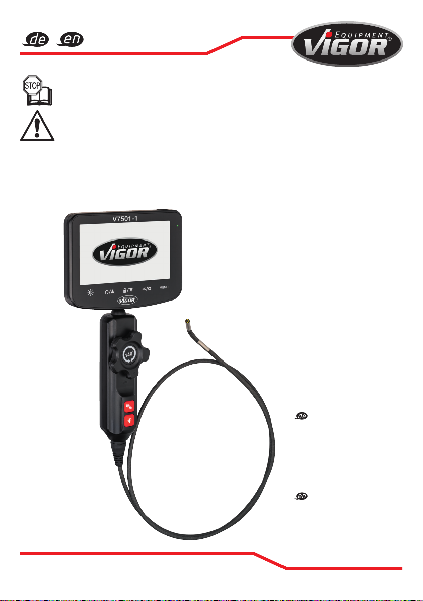
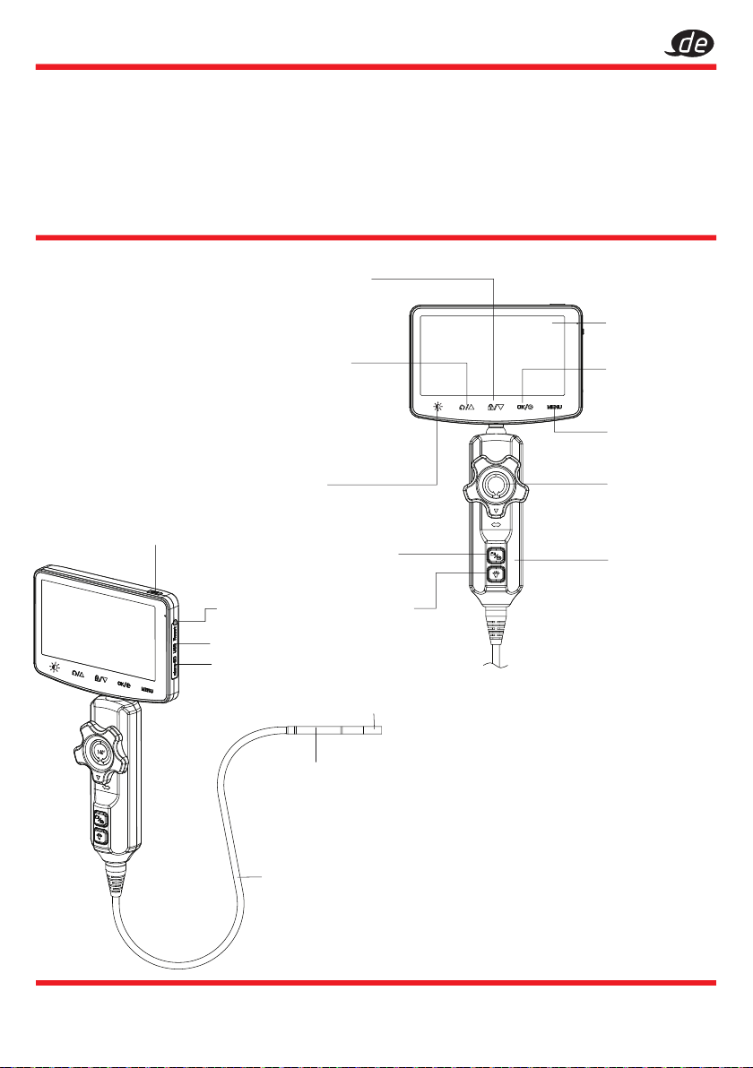
Dieses Videoendoskop mit ?4,9 mm Schwenksonde
wurde nach den damals gültigen technischen Normen
und Standards entwickelt und hergestellt und gilt als
betriebssicher. Dennoch kann das Gerät eine Gefahr
darstellen, wenn es nicht bestimmungsgemäß oder
von nicht qualifiziertem Fachpersonal unsachgemäß
verwendet wird. Vergewissern Sie sich, dass jede Person,
die dieses Gerät benutzt oder Wartungsarbeiten
durchführt, diese Betriebsanleitung sorgfältig liest und
alle darin enthaltenen Informationen vollständig versteht,
bevor sie das Gerät benutzt. Modifikationen jeglicher Art
sowie An- und Umbauten am Gerät sind verboten.
Alle Sicherheits-, Warn- und Bedienungshinweise
auf dem Gerät müssen leserlich gehalten werden.
Beschädigte Schilder oder Aufkleber sind sofort
zu ersetzen. Alle angegebenen Einbauwerte bzw.
Einstellbereiche müssen eingehalten werden.
2. Haftung des Eigentümers
•
Bewahren Sie die Betriebsanleitung immer
in der Nähe des Gerätes auf.
•
Das Werkzeug darf nur verwendet werden,
wenn es in einwandfreiem Zustand ist.
•
Alle Sicherheitseinrichtungen müssen immer in Reichweite
sein und sollten regelmäßig überprüft werden.
•
Neben den Sicherheitshinweisen in dieser Betriebsanleitung
müssen die für den Einsatzbereich des Werkzeugs
gültigen allgemeinen Vorschriften zur Unfallverhütung,
zur Sicherheit und zum Umweltschutz beachtet werden.
3. Bestimmungsgemäße Verwendung
Dieses Videoendoskop mit ?4,9 mm Schwenksonde
ist ausschließlich für die Schadensdiagnose mit
Bildaufnahmen an schwer zugänglichen Stellen zu
verwenden, z.B. Getriebegehäuse, Zylinderwände/
Kolbenköpfe, Ventile, Hohlräume, Hohlschäfte etc.
Dieses Videoendoskop mit ?4,9 mm Schwenksonde
darf nicht für medizinische Anwendungen z.B. an
Menschen oder Tieren verwendet werden.
Die Betriebssicherheit ist nur bei bestimmungsgemäßer
Verwendung entsprechend den Angaben in
der Betriebsanleitung gewährleistet.
Die Verwendung und Wartung des Videoendoskops mit
?4,9 mm Schwenksonde muss immer in Übereinstimmung
mit den örtlichen Landes- oder Bundesvorschriften erfolgen.
•
Jede Abweichung vom bestimmungsgemäßen Gebrauch
und/oder jede falsche Anwendung der Werkzeuge ist
nicht zulässig und wird als unsachgemäße Verwendung
betrachtet.
•
Jegliche Ansprüche gegen den Hersteller und/oder
seine Beauftragten aufgrund von Schäden, die durch
unsachgemäßen Gebrauch des Werkzeugs entstehen,
sind ausgeschlossen.
•
Für Personen- oder Sachschäden, die durch unsachge-
mäßen Gebrauch des Geräts verursacht werden, haftet
ausschließlich der Besitzer.
•
Verwenden Sie das Werkzeug nicht in
explosionsgefährdeten Bereichen.
•
Biegen Sie die Sonde nicht mehr als 140°.
•
Verwenden Sie das Videoendoskop mit der ?4,9 mm
Schwenksonde nicht bei niedrigen Temperaturen unter
-10°C oder hohen Temperaturen über 60°C.
•
Tauchen Sie das Gerät nicht in Chemikalien ein.
•
Gießen Sie keine Flüssigkeiten auf dieses Produkt.
•
Das Display und der Gri dürfen nur mit einem trockenen
Tuch gereinigt werden.
•
Die Linse kann mit einem leicht feuchten Tuch gereinigt
werden, jedoch nicht mit ätzenden Substanzen (z.B. Aceton)
•
Die Sonde kann vor dem Inspizieren des Werkstücks von
Hand, ohne großen Kraftaufwand vorgeformt werden.
Starke Verformungen, können zum Bruch der Sonde und /
oder den Leitungen innerhalb der Sonde führen.
•
Stellen Sie den Drehknopf des Objektivs nach der
Verwendung des Produkts in die Ausgangsposition.
•
Wenn das Produkt nicht benutzt wird, legen Sie es bitte in
die Originalverpackung zurück und bewahren Sie es an
einem trockenen und belüfteten Ort auf.
•
4. Gefahren, die bei der Verwendung
des Geräts auftreten können
Prüfen Sie das Videoendoskop mit ?4,9 mm Schwenksonde
vor jedem Gebrauch auf volle Funktionsfähigkeit. Benutzen
Sie das Gerät nicht, wenn seine Funktionstüchtigkeit nicht
gewährleistet ist oder wenn Schäden festgestellt werden.
Wenn festgestellt wird, dass das Gerät nicht funktionstüchtig
ist und das Gerät trotzdem benutzt wird, besteht die Gefahr
von schweren Körper-, Gesundheits- und Sachschäden.
Die volle Funktionstüchtigkeit ist gewährleistet, wenn das
Gerät absolut unbeschädigt ist.
5. WARNUNG VOR EXPLOSIVEN GASEN
•
Verwenden Sie das Videoendoskop mit
?4,9 mm
Schwenksonde
nicht mit leicht entzündlichen Produkten oder in explosionsgefährdeten
Räumen, z.B. mit brennbarem Gas oder Staub.
•
Gehen Sie besonders vorsichtig mit dem Gerät um. Vermeiden Sie es,
es auf eine harte Oberfläche fallen zu lassen und setzen Sie es keinem
Druck oder einer anderen Form von mechanischer Belastung aus.
Halten Sie das Gerät von extremer Hitze und Kälte fern.
•
Reparaturarbeiten dürfen nur von autorisierten Personen durchgeführt
werden.
•
Es ist strengstens untersagt, Werkzeuge zu manipulieren oder zu
missbrauchen oder Notreparaturen durchzuführen.