AEMC instruments PMR-1 User manual

n PHASE & MOTOR ROTATION
TESTER
n PROBADOR DE FASE &
ROTACIÓN DE MOTOR
PMR-1
ENGLISH
User Manual
ESPAÑOL
Manual de instrucciones

Owner’s Record
The serial number for the Model PMR-1 is located on the backside
of the instrument. Please record this number and purchase date for
your records.
PHASE & MOTOR ROTATION TESTER MODEL PMR-1
CATALOG #: 2121.04
SERIAL #: ___________________________________________
PURCHASE DATE: ____________________________________
DISTRIBUTOR: _______________________________________

Phase & Motor Rotation Tester Model PMR-1
1
Table of Contents
ENGLISH ............................................................................... 1
ESPAÑOL............................................................................. 15
1. INTRODUCTION..................................................... 2
Warning ..................................................................................2
1.1 International Electrical Symbols .....................................2
1.2 Receiving Your Shipment ...............................................3
1.3 Ordering Information ......................................................3
2. PRODUCT FEATURES............................................ 4
2.1 Description .....................................................................4
2.2 Control Features ............................................................5
3. SPECIFICATIONS................................................... 6
4. OPERATION ........................................................... 7
4.1 Pretest Procedure ..........................................................7
4.2 Phase Rotation Tester Operation ...................................7
4.3 Motor Rotation Tester Operation ....................................8
5. MAINTENANCE.................................................... 10
5.1 Battery Replacement....................................................10
5.2 Fuse Replacement .......................................................10
5.3 Cleaning and Storage ..................................................11
Repair and Calibration..................................................................12
Technical and Sales Assistance ...................................................12
Limited Warranty ..........................................................................13
Warranty Repairs..........................................................................13

2
Phase & Motor Rotation Tester Model PMR-1
CHAPTER 1
INTRODUCTION
Warning
• Read the user manual before operating and follow all
safety information.
• Only use the meter as specied in this user manual.
• Do not operate the meter if the body or test leads look
damaged.
• This meter has been designed and tested to meet
the Safety Requirements for Electronic Measuring
Apparatus, IEC-1010 (EN 61010) and other safety
standards. It is ideal for installing conveyor lines,
pumps, systems and other electrical interconnected
devices as well as verifying proper wiring.
1.1 International Electrical Symbols
This symbol signies that the instrument is protected by
double or reinforced insulation. Use only specied replace-
ment parts when servicing the instrument.
This symbol on the instrument indicates a WARNING
and that the operator must refer to the user manual for
instructions before operating the instrument. In this manual,
the symbol preceding instructions indicates that if the
instructions are not followed, bodily injury, installation/
sample and product damage may result.
Risk of electric shock. The voltage at the parts marked with
this symbol may be dangerous.

Phase & Motor Rotation Tester Model PMR-1
3
1.2 Receiving Your Shipment
Upon receiving your shipment, make sure that the contents are con-
sistent with the packing list. Notify your distributor of any missing
items. If the equipment appears to be damaged, le a claim imme-
diately with the carrier and notify your distributor at once, giving a
detailed description of any damage. Save the damaged packing
container to substantiate your claim.
1.3 Ordering Information
Phase and Motor Rotation Tester ......................... Cat. #2121.04
Includes meter, carrying case and test leads (black, red and blue) with large
alligator clips, one 9V battery (installed) and user manual.

4
Phase & Motor Rotation Tester Model PMR-1
CHAPTER 2
PRODUCT FEATURES
2.1 Description
This economical three-in-one test tool is a must for any plant main-
tenance staff and will identify proper sequencing for three phase
power very quickly and easily.
This is also an ideal tool for measuring the proper rotation of
motors, conveyors, pumps and other electrical devices intercon-
nected on the power line system before installation.
• This meter provides 3 functions in one unit.
1. Open Phase Indication
2. Phase Rotation Indication
3. Motor Rotation Indication
• Identies 3-phase sequence and checks for open phase.
• Battery operated.
• Meets IEC 1010 (EN 61010) safety requirements.
• Includes three color-coded test leads with alligator clips for easy
connection to the device under test.

Phase & Motor Rotation Tester Model PMR-1
5
2.2 Control Features
Figure 1
1) Phase rotation input terminals
2) Phase rotation indicators
3) Motor tester power indicator
4) Motor rotation input terminals
5) Open phase indicators
6) Motor tester power button
7) Motor rotation indicators

6
Phase & Motor Rotation Tester Model PMR-1
CHAPTER 3
SPECIFICATIONS
Input Voltage:
100VAC up to 600VAC max.
Frequency Range: 45 to 70Hz
Power Requirement: 9V battery
Power Consumption:
Current Draw - Approximately 14mA for motor rotation test
Approximately 7mA for phase rotation test
Dimension:
6.02 x 2.83 x 1.37" (153 x 72 x 35mm)
Weight:
Approximately 6.37 oz (182g) including battery
Installation Category:
IEC 1010 (EN 61010), 600V, Cat. III

Phase & Motor Rotation Tester Model PMR-1
7
CHAPTER 4
OPERATION
4.1 Pretest Procedure
1. Press the Red motor rotation test button and verify that the
Green LED is brightly lit. If it is, the battery is OK. If it is dimly
lit, see Chapter 5 for battery replacement.
2. Connect the “A” (black) and “B” (red) leads on the phase rota-
tion side of the meter to a known AC power source between
100 and 600VAC. Make sure that the “A” LED lights. If it does
not, refer to Chapter 5 of this manual and the discussion on
fuse replacement.
3. Connect the “C” (blue) and “B” (red) leads on the phase rota-
tion side of the meter to a known AC power source between
100 and 600VAC. Make sure that the “C” LED lights. If it does
not, refer to Chapter 5 of this manual and the discussion on
fuse replacement.
4.2 Phase Rotation Tester Operation
1. Connect the test leads to the 3-phase input terminals marked
A-B-C.
2. Connect the alligator clips to the terminals of the 3-phase
power source to be tested. Connecting order is optional.
3. Make sure that all three LEDs (A-B-C) for open phase check
are on. If all are on, there is no open phase power problem.
If LED “A” or “C” are out, verify that power is present using a
voltage tester.

8
Phase & Motor Rotation Tester Model PMR-1
Open phase check LED “A” is not on:
Open phase on terminal where BLACK alligator clip is
connected.
LED “B” is not on:
Open phase on terminal where RED alligator clip is con-
nected.
LED “C” is not on:
Open phase on terminal where BLUE alligator clip is con-
nected.
4. Check the rotating direction by viewing the rotation indicator
LEDs. If the counter clockwise LED is lit, alternate the connec-
tion of two of the three alligator clips.
If the clockwise LED is lit, the phase sequence is A, B and C in
the same order in which the BLACK, RED and BLUE alligator
clips are connected to the power source terminals.
4.3 Motor Rotation Tester Operation
1. Make sure the power is turned OFF on the motor under test
and that no voltage is present.
2. Connect the test leads to the motor input terminals in the
following order: Black to “A”, Red to “B” and Blue to “C”. Then
press the power button (see Figure 2). The power indicator
Green LED should light.
WARNING: If the Red clockwise or counter-clockwise LED is
lit before rotating the motor shaft, it means there is voltage
present. Stop the test, disconnect the test leads and turn off the
external power.
If the clockwise red LED turns on when rotating the motor
shaft in the clockwise direction, it means the 3-phase motor
connection to the power source is in the A-B-C sequence and
the 3-phase motor should rotate clockwise when powered.

Phase & Motor Rotation Tester Model PMR-1
9
3. Rotate the motor shaft counter-clockwise. If the counter-clock-
wise red LED turns on, it means the 3-phase motor connection
to the power source is in the A-B-C sequence and the 3-phase
motor should rotate clockwise when powered.
4. If you require the motor to rotate counter-clockwise, change
the power source connections to a B-A-C sequence. The
motor should then rotate counter-clockwise when powered.
Figure 2

10
Phase & Motor Rotation Tester Model PMR-1
CHAPTER 5
MAINTENANCE
5.1 Battery Replacement
Always disconnect all leads before replacing a battery
or fuse.
The battery will need to be replaced when the Green LED is dimly lit.
• Remove the screws on the back cover, then open the case. Take
out the battery and replace with a new 9V battery.
(Type NEDA 1604, 6LF22, 6LR61)
• Replace the back cover on the case.
5.2 Fuse Replacement
It is necessary to replace the fuse when the “A” or “C” LED indicator
on the phase rotation side shows no connection (LED is not lit when
power is applied to the A-B-C leads).
• Remove the screws on the back cover, then open the case. With
the circuit board exposed and phase rotation side on the top
(away from you), take out the defective fuse and replace it with a
fuse rated for 200mA at 250V (Cat. #2973.02).
• If the “C” LED (blue lead) did not light, replace the fuse on the
left side (unit face down). If the “A” LED (black lead) did not light,
replace the fuse on the right.
• Replace the back cover on the case.

Phase & Motor Rotation Tester Model PMR-1
11
5.3 Cleaning and Storage
To avoid electrical shock or damage to the meter, do not
get water inside the case.
• Periodically wipe the case with a damp cloth and detergent
• Do not use abrasives or solvents.
• If the meter is not to be used for a period of longer then 60 days,
remove the battery and store them separately.

12
Phase & Motor Rotation Tester Model PMR-1
Repair and Calibration
To ensure that your instrument meets factory specications, we recommend
that it be submitted to our factory Service Center at one-year intervals for
recalibration, or as required by other standards or internal procedures.
For instrument repair and calibration:
You must contact our Service Center for a Customer Service Authorization
Number (CSA#). This will ensure that when your instrument arrives, it will
be tracked and processed promptly. Please write the CSA# on the outside
of the shipping container. If the instrument is returned for calibration, we
need to know if you want a standard calibration, or a calibration traceable to
N.I.S.T. (includes calibration certicate plus recorded calibration data).
Ship To: Chauvin Arnoux®, Inc. d.b.a. AEMC® Instruments
15 Faraday Drive • Dover, NH 03820 USA
Tel: (800) 945-2362 or (603) 749-6434 (Ext. 360)
Fax: (603) 742-2346 or (603) 749-6309
(Or contact your authorized distributor)
Costs for repair, standard calibration, and calibration traceable to N.I.S.T.
are available.
NOTE: You must obtain a CSA# before returning any instrument.
Technical and Sales Assistance
If you are experiencing any technical problems, or require any assistance
with the proper operation or application of your instrument, please call, mail,
fax or e-mail our technical support hotline:
Chauvin Arnoux®, Inc. d.b.a. AEMC® Instruments
200 Foxborough Boulevard • Foxborough, MA 02035, USA
Phone: (800) 343-1391 or (508) 698-2115
Fax: (508) 698-2118
www.aemc.com
NOTE: Do not ship Instruments to our Foxborough, MA address.

Phase & Motor Rotation Tester Model PMR-1
13
Limited Warranty
The Model PMR-1 is warranted to the owner for a period of one year from
the date of original purchase against defects in manufacture. This limited
warranty is given by AEMC® Instruments, not by the distributor from whom
it was purchased. This warranty is void if the unit has been tampered with,
abused or if the defect is related to service not performed by AEMC®
Instruments.
For full and detailed warranty coverage, please read the Warranty Cov-
erage Information, which is attached to the Warranty Registration Card
(if enclosed) or is available at www.aemc.com. Please keep the Warranty
Coverage Information with your records.
What AEMC® Instruments will do: If a malfunction occurs within the one-
year period, you may return the instrument to us for repair, provided we have
your warranty registration information or a proof of purchase. AEMC® Instru-
ments will, at its option, repair or replace the faulty material.
REGISTER ONLINE AT:
www.aemc.com
Warranty Repairs
What you must do to return an Instrument for Warranty Repair:
First, request a Customer Service Authorization Number (CSA#) by phone
or by fax from our Service Department (see address below), then return the
instrument along with the signed CSA Form. Please write the CSA# on the
outside of the shipping container. Return the instrument, postage or ship-
ment pre-paid to:
Chauvin Arnoux®, Inc. d.b.a. AEMC® Instruments
Service Department • 15 Faraday Drive • Dover, NH 03820 USA
Tel: (800) 945-2362 or (603) 749-6434 (Ext. 360)
Fax: (603) 742-2346 or (603) 749-6309
Caution: To protect yourself against in-transit loss, we recommend you
insure your returned material.
NOTE: You must obtain a CSA# before returning any instrument.

14
Phase & Motor Rotation Tester Model PMR-1
NOTES:

Probador de Fase & Rotación de Motor Modelo PMR-1
15
Tabla de Contenidos
ENGLISH ............................................................................... 1
ESPAÑOL............................................................................. 15
1. INTRODUCCIÓN .................................................. 16
1.1 Símbolos Eléctricos Internacionales ............................16
1.2 Recepción de su embarque .........................................17
1.3 Información para poner una orden...............................17
2. CARACTERÍSTICAS DEL PRODUCTO.................. 18
2.1 Descripción...................................................................18
2.2 Características de los Controles ..................................19
3. ESPECIFICACIONES............................................ 20
4. OPERACIÓN......................................................... 21
4.1 Procedimiento Pre-ensayo...........................................21
4.2 Operación del Probador de Rotación de Fases ...........21
4.3 Operación del Probador de Rotación de Motor............22
5. MAINTENANCE.................................................... 24
5.1 Reemplazo de la Batería..............................................24
5.2 Reemplazo de un Fusible ............................................24
5.3 Limpieza y Almacenaje ................................................25
Reparación y Calibración .............................................................26
Asistencia Técnica y de Ventas....................................................26
Garantía Limitada.........................................................................27
Reparaciones bajo Garantía ........................................................27

16
Probador de Fase & Rotación de Motor Modelo PMR-1
CAPITULO 1
INTRODUCCIÓN
ADVERTENCIA
• Lea el manual antes de empezar a utilizar el instru-
mento y siga todas las informaciones de seguridad.
• Utilice el instrumento como se indica en el manual.
• No utilice el instrumento o las puntas de pruebas si
paracen dañadas.
• Este probador ha sido diseñado y probado para sat-
isfacer los Requerimientos de Seguridad para Apara-
tos de Medición Electrónicos, IEC-1010 (EN61010) y
otros estándares de seguridad. Es ideal para instalar
cintas transportadoras, bombas, sistemas y otros
dispositivos eléctricos interconectados como tam-
bién vericar un correcto cableado.
1.1 Símbolos Eléctricos Internacionales
Este símbolo signica que el instrumento esta protegido
por un doble aislamiento o un aislamiento reforzado. Utilice
piezas de repuesto especicadas por AEMC cuando repare
el instrumento.
Este símbolo en el instrumento signica ADVERTENCIA
en este caso consulte el manual de instrucciones antes de
utilizar el aparato. En el supuesto que aparezca esta señal,
signicara no se han seguido las instrucciones de uso, si no
se respetan o realizan correctamente, pueden ocasionar un
accidente corporal o dañar el equipo o las instalaciones.
Riesgo de choque eléctrico. Los componentes marcados
con este símbolo pueden ser peligrosos.

Probador de Fase & Rotación de Motor Modelo PMR-1
17
1.2 Recepción de su embarque
Luego de recibido su embarque, asegúrese que el contenido
coincide con la guía de despacho. Avise a su distribuidor sobre
cualquier parte faltante. Si el equipo aparece dañado, presente un
reclamo inmediatamente al transportador y avise inmediatamente
a su distribuidor, dando una descripción detallada de los daños.
Conserve el empaque dañado para respaldar su reclamo. No utilice
un instrumento que aparezca dañado.
1.3 Información para poner una orden
Probador de Fase & Rotación de Motor
Modelo PMR-1......................................................... Cat. #2121.04
Incluye una bolsa de transporte, cables (negro, rojo y azúl) conpinzas
grandes, batería 9V, y manual del usuario.

18
Probador de Fase & Rotación de Motor Modelo PMR-1
CAPÍTULO 2
CARACTERÍSTICAS DEL PRODUCTO
2.1 Descripción
Esta herramienta de prueba económica de tres en uno es indis-
pensable para cualquier personal de mantenimiento de planta y
muy rápidamente y fácilmente identicará la secuencia apropiada
para potencia de tres fases.
Esta es también una herramienta ideal para medir la rotación
apropiada de motores, transportadores, bombas y otros aparatos
eléctricos interconectados en el sistema de alimentación antes de
instalación. Este medidor ha sido diseñado de acuerdo con los
Requerimientos de Seguridad para Aparatos de Medida Electrónica
EN 61010.
• Este medidor proporciona tres funciones en una unidad.
1. Indicación de Fase Abierta
2. Indicación de Rotación de Fase
3. Indicación de Rotación de Motor
• Identica la secuencia de las 3 fases y prueba si hay una fase
abierta.
• Operado por Batería.
• Cumple con los requerimientos de seguridad IEC-1010
(EN 61010).
• Incluye tres cables con pinzas caimán para conectarlo fácil-
mente al dispositivo bajo prueba.
This manual suits for next models
1
Table of contents
Languages:
Other AEMC instruments Test Equipment manuals
AEMC instruments
AEMC instruments 6471 User manual
AEMC instruments
AEMC instruments CA7027 User manual
AEMC instruments
AEMC instruments 4620 User manual
AEMC instruments
AEMC instruments 6416 User manual
AEMC instruments
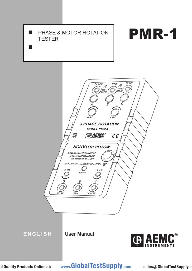
AEMC instruments 2121.04 User manual
AEMC instruments
AEMC instruments 3640 User manual
AEMC instruments
AEMC instruments 6240 User manual
AEMC instruments
AEMC instruments 6470 User manual
AEMC instruments
AEMC instruments 6422 User manual
AEMC instruments
AEMC instruments 6418 User manual
