AEMC instruments 2121.04 User manual

PHASE & MOTOR ROTATION
TESTER
PMR-1
ENGLISH
User Manual
®
INSTRUMENTS
B A CA B C
BLACK RED BLUE
A B C
BLACK RED BLUE
AB C
POWER
DO NOT CONNECT TO LIVE VOLTAGE!
MOTOR ROTATION
DETERMINED WHILE
FACING MOTOR SHAFT
MOTOR ROTATION
CAT III
B A CA B C
600 V
CAT III
600 V
CAT III
3 PHASE ROTATION
MODEL PMR-1
www.GlobalTestSupply.com
Find Quality Products Online at: sales@GlobalTestSupply.com

Statement of Compliance
Chauvin Arnoux®, Inc. d.b.a. AEMC®Instruments
certifies that this instrument has been calibrated
using standards and instruments traceable to
international standards.
We guarantee that at the time of shipping your
instrument has met its published specifications.
The recommended verification interval for this
instrument is 12 months and begins on the date
of receipt by the customer.
Serial #: ____________________________
Catalog #: 2121.04
Model #: PMR-1
Please fill in the appropriate date as indicated:
Date Received: ________________________
Date Verification Due: _____________________
www.GlobalTestSupply.com
Find Quality Products Online at: sales@GlobalTestSupply.com

Table of Contents
1. INTRODUCTION..................................................... 3
1.1 International Electrical Symbols .....................................4
1.2 DenitionofMeasurementCategories...........................4
1.3 ReceivingYourShipment ...............................................5
1.4 OrderingInformation ......................................................5
2. PRODUCT FEATURES............................................ 6
2.1 Description .....................................................................6
2.2 ControlFeatures.............................................................7
3. SPECIFICATIONS................................................... 8
3.1 Electrical.........................................................................8
3.2 Mechanical .....................................................................8
3.3 Environmental ................................................................9
3.4 Safety .............................................................................9
4. OPERATION ......................................................... 10
4.2 PhaseRotationTesterOperation .................................10
4.2.1 PretestProcedure ........................................10
4.2.2 Operation .....................................................10
4.3 MotorRotationTesterOperation ..................................11
4.3.1 PretestProcedure ........................................11
4.3.2 Operation .....................................................11
www.GlobalTestSupply.com
Find Quality Products Online at: sales@GlobalTestSupply.com

5. MAINTENANCE.................................................... 13
5.1 BatteryReplacement....................................................13
5.2 FuseReplacement .......................................................13
5.2.1 PhaseRotationSide ....................................13
5.2.2 Motor Rotation Side .....................................14
5.3 CleaningandStorage...................................................14
Limited Warranty ..........................................................................16
WarrantyRepairs..........................................................................16
www.GlobalTestSupply.com
Find Quality Products Online at: sales@GlobalTestSupply.com

Phase&MotorRotationTesterModelPMR-1
3
CHAPTER 1
INTRODUCTION
Warning
Toensuresafeoperationandusageofthisinstrument,follow
instructionsinthismanual.FailuretoobserveWarningsmay
resultinSEVEREinjuryordeath.
Never use the motor polarity tester on energized•
motors!
ThePMR-1PhaseandMotorRotationTesterconformsto•
EN61010-1,600VCat.III.
Itisrecommendedforuseindistributionlevelandxed•
installations, as well as lesser installations, and not for
primarysupplylines,overheadlinesandcablesystems.
Donotexceedthemaximumoverloadlimitsperfunction•
(seespecications)nor the limits markedontheinstru-
ment itself. Never apply more than 600VACrms between
thetestleadandearthground.
Inspectthetester,testleadsandaccessoriesbeforeeach•
use.Donotuseanydamagedparts.
Never ground yourself when taking measurements. Do•
nottouchexposedcircuitelementsortestprobetips.
Donotoperatethetesterinanexplosiveatmosphere.•
Exerciseextremecautionwhenmeasuringvoltage>50V•
andcurrent>10mA.
Neverreplaceafusewithoneofadifferentrating.•
Removetestleadsbeforeopeningthecase.•
Do not use in a manner not specied or the protection•
affordedbytheinstrumentmaybeimpaired.
www.GlobalTestSupply.com
Find Quality Products Online at: sales@GlobalTestSupply.com

4
Phase&MotorRotationTesterModelPMR-1
1.1 International Electrical Symbols
Signifies that the instrument is protected by double or rein-
forced insulation.
This symbol on the instrument indicates a WARNING and that the
operator must refer to the user manual for instructions before
operating the instrument. In this manual, the symbol preceding
instructions indicates that if the instructions are not followed,
bodily injury, installation/sample and/or product damage may
result.
Risk of electric shock. The voltage at the parts marked with this
symbol may be dangerous.
In conformity with WEEE 2002/96/EC
1.2 Definition of Measurement Categories
Cat. I: For measurements on circuits not directly connected to
theACsupplywalloutletsuchasprotectedsecondaries,
signallevel,andlimitedenergycircuits.
Cat. II: For measurements performed on circuits directly con-
nected to the electrical distribution system. Examples
are measurements on household appliances or portable
tools.
Cat. III: For measurements performed in the building installation
atthedistributionlevelsuchasonhardwiredequipmentin
xedinstallationandcircuitbreakers.
Cat. IV: For measurements performed at the primary electrical
supply(<1000V) such as on primary overcurrent protec-
tiondevices,ripplecontrolunits,ormeters.
www.GlobalTestSupply.com
Find Quality Products Online at: sales@GlobalTestSupply.com

Phase&MotorRotationTesterModelPMR-1
5
1.3 Receiving Your Shipment
Uponreceivingyourshipment,makesurethatthecontentsarecon-
sistentwiththe packing list.Notifyyourdistributor of anymissing
items.Iftheequipmentappearstobedamaged,leaclaimimme-
diately with the carrier and notify your distributor at once, giving
adetaileddescriptionofanydamage.Savethedamagedpacking
containertosubstantiateyourclaim.
1.4 Ordering Information
Phase and Motor Rotation Tester ......................... Cat. #2121.04
Includes meter, carrying case and test leads (black, red and blue) with large
alligator clips, one 9V battery (installed) and user manual.
www.GlobalTestSupply.com
Find Quality Products Online at: sales@GlobalTestSupply.com

6
Phase&MotorRotationTesterModelPMR-1
CHAPTER 2
PRODUCT FEATURES
2.1 Description
Thisthree-in-onetesttoolisamustforanyplantmaintenancestaff
and will identify proper sequencing for three phase power very
quicklyandeasily.
This is also an ideal tool for measuring the proper rotation of
motors, conveyors, pumps and other electrical devices intercon-
nectedonthepowerlinesystembeforeinstallation.
• Thismeterprovides3functionsinoneunit.
1. OpenPhaseIndication
2. PhaseRotationIndication
3. Motor Rotation Indication
• Identies3-phasesequenceandchecksforopenphase.
• Batteryoperated.
• MeetsIEC1010(EN61010)safetyrequirements.
• Includesthreecolor-codedtestleadswithalligatorclipsforeasy
connectiontothedeviceundertest.
www.GlobalTestSupply.com
Find Quality Products Online at: sales@GlobalTestSupply.com

Phase&MotorRotationTesterModelPMR-1
7
2.2 Control Features
B A C A B C
BLACK RED BLUE
ABC
BLACK RED BLUE
A B C
POWER
DO NOT CONNECT TO LIVE VOLTAGE!
MOTOR ROTATION
DETERMINED WHILE
FACING MOTOR SHAFT
MOTOR ROTATION
CAT III
B A CAB C
600 V
CAT III
600 V
CAT III
3 PHASE ROTATION
MODEL PMR-1
1
5
6
7
4
2
3
Figure 1
1)Phaserotationinputterminals
2)Phaserotationindicators
3)Motortesterpowerindicator
4)Motorrotationinputterminals
5)Openphaseindicators
6)Motortesterpowerbutton
7)Motorrotationindicators
www.GlobalTestSupply.com
Find Quality Products Online at: sales@GlobalTestSupply.com

8
Phase&MotorRotationTesterModelPMR-1
CHAPTER 3
SPECIFICATIONS
3.1 Electrical
Input Voltage:100VACupto600VACmax.
Frequency Range: 45 to 70Hz
Overload Protection: 600VAC
Operating Time: 10minONmaxat600VAC and 10 min OFF
Power Source:9Vbattery(NEDA1604,IEC6F22)
Power Consumption:
CurrentDraw-14mAapprox.formotorrotationtest
7mAapprox.forphaserotationtest
Battery Life: 200typical
Low Battery Indication: The Batt LED does not light when test
buttonispressed.
3.2 Mechanical
Dimension:6.02x2.83x1.37"(153x72x35mm)
Weight:6.37oz(182g)approx.includingbattery
www.GlobalTestSupply.com
Find Quality Products Online at: sales@GlobalTestSupply.com

Phase&MotorRotationTesterModelPMR-1
9
3.3 Environmental
Altitude: upto2000meters
Ambient Temperature: 32to104°F(0to40°C)
Relative Humidity: 80%max
3.4 Safety
Indoor Use
IEC1010(EN61010)
600VCat.III
PollutionDegree2
www.GlobalTestSupply.com
Find Quality Products Online at: sales@GlobalTestSupply.com

10
Phase&MotorRotationTesterModelPMR-1
CHAPTER 4
OPERATION
4.2 Phase Rotation Tester Operation
4.2.1 Pretest Procedure
1. Connect the “A” (black) and “B” (red) leads on the phase
rotationsideofthemetertoaknownACpowersourcebetween
100and600VAC.Makesurethatthe“A”LEDlights.Ifitdoes
not,refer toChapter5of thismanualand thediscussionon
fusereplacement.
2. Connectthe“C”(blue)and“B”(red)leadsonthephaserotation
sideofthemetertoaknownACpowersourcebetween100
and600VAC.Makesurethatthe“C”LEDlights.Ifitdoesnot,
refertoChapter5ofthismanualandthediscussiononfuse
replacement.
4.2.2 Operation
1. Connectthetestleadstothe3-phaseinputterminalsmarked
A-B-C.
2. Connect the alligator clips to the terminals of the 3-phase
powersourcetobetested.Connectingorderisoptional.
3. MakesurethatallthreeLEDs(A-B-C)foropenphasecheck
areon.Ifallareon,thereisnoopenphasepowerproblem.
IfLED“A”or“C”areout,verifythatpowerispresentusinga
voltagetesterorDMM.
www.GlobalTestSupply.com
Find Quality Products Online at: sales@GlobalTestSupply.com

Phase&MotorRotationTesterModelPMR-1
11
Open phase check LED “A” is not on: Openphaseon
terminalwhereBLACKalligatorclipisconnected.
LED “B” is not on: OpenphaseonterminalwhereRED
alligatorclipisconnected.
LED “C” is not on: OpenphaseonterminalwhereBLUE
alligatorclipisconnected.
4. Checktherotatingdirectionby viewing the rotation indicator
LEDs.IfthecounterclockwiseLEDislit,alternatetheconnec-
tionoftwoofthethreealligatorclips.
IftheclockwiseLEDislit,thephasesequenceisA,BandCin
thesameorderinwhichtheBLACK,REDandBLUEalligator
clipsareconnectedtothepowersourceterminals.
4.3 Motor Rotation Tester Operation
WARNING: NEVER USE ON ENERGIZED MOTORS!
Use a multimeter to verify that no voltage is present on
the motor winding.
4.3.1 Pretest Procedure
1. Press the Red motor rotation test button and verify that the
GreenLEDisbrightlylit.Ifitis,thebatteryisOK.Ifitisdimly
lit,seeChapter5forbatteryreplacement.
4.3.2 Operation
1. MakesurethepoweristurnedOFFonthemotorunder test
andthatnovoltageispresent.
2. Connect the test leads to the motor input terminals in the
followingorder:Blackto“A”,Redto“B”andBlueto“C”.Then
press the power button (see Figure 2). The power indicator
GreenLEDshouldlight.
www.GlobalTestSupply.com
Find Quality Products Online at: sales@GlobalTestSupply.com

12
Phase&MotorRotationTesterModelPMR-1
WARNING: If the Red clockwise or counter-clockwise LED
islitbeforerotatingthemotorshaft,itmeansthereisvoltage
present.Stopthetest,disconnectthetestleadsandturnoffthe
externalpower.
If the clockwise red LED turns on when rotating the motor
shaft in the clockwise direction, it means the 3-phase motor
connectiontothepowersourceisintheA-B-Csequenceand
the3-phasemotorshouldrotateclockwisewhenpowered.
3. Rotatethemotorshaftcounter-clockwise.Ifthecounter-clock-
wiseredLEDturnson,itmeansthe3-phasemotorconnection
tothepowersourceisintheA-B-Csequenceandthe3-phase
motorshouldrotateclockwisewhenpowered.
4. Ifyou require the motor torotate counter-clockwise, change
the power source connections to a B-A-C sequence. The
motorshouldthenrotatecounter-clockwisewhenpowered.
B A CAB C
BLACKRED BLUE
ABC
POWER
DO NOT CONNECT TO LIVE VOLTAGE!
MOTOR ROTA TION
DETERMINED WHILE
FA CING MOTOR SHAFT
MOTOR ROTATION
CATIII
3 PHASE ROTATION
MODEL PMR-1
Power
Button
USE ONLY ON
NON-ENERGIZED
MOTORS!
Figure 2
www.GlobalTestSupply.com
Find Quality Products Online at: sales@GlobalTestSupply.com

Phase&MotorRotationTesterModelPMR-1
13
CHAPTER 5
MAINTENANCE
5.1 Battery Replacement
WARNING: Always disconnect all leads before replacing
a battery or fuse.
ThebatterywillneedtobereplacedwhentheGreenLEDisdimlylit.
• Removethescrewsonthebackcover,thenopenthecase.Take
outthebatteryandreplacewithanew9Vbattery.
(TypeNEDA1604,6LF22,6LR61)
• Replacethebackcoveronthecase.
5.2 Fuse Replacement
5.2.1 Phase Rotation Side
Itisnecessarytoreplacethefusewhenthe“A”or“C”LEDindicator
onthephaserotationsideshowsnoconnection(LEDisnotlitwhen
powerisappliedtotheA-B-Cleads).
• Removethescrewsonthebackcover,thenopenthecase.With
the circuit board exposed and phase rotation side on the top
(awayfromyou),takeoutthedefectivefuseandreplaceitwitha
fastblowfuse200mAat250V(Cat.#2973.02).
www.GlobalTestSupply.com
Find Quality Products Online at: sales@GlobalTestSupply.com

14
Phase&MotorRotationTesterModelPMR-1
• Ifthe“C”LED(bluelead)didnotlight,replacethefuseonthe
leftside(unitfacedown).Ifthe“A”LED(blacklead)didnotlight,
replacethefuseontheright.
• Replacethebackcoveronthecase.
5.2.2 Motor Rotation Side
NOTE: The motor rotation is fuse protected but not user
replaceable.Pleasereturnyourinstrumentforservice.
5.3 Cleaning and Storage
To avoid electrical shock or damage to the meter, do not
get water inside the case.
• Periodicallywipethecasewithadampclothanddetergent
• Donotuseabrasivesorsolvents.
• Ifthemeterisnottobeusedforaperiodoflongerthen60days,
removethebatteryandstorethemseparately.
www.GlobalTestSupply.com
Find Quality Products Online at: sales@GlobalTestSupply.com

www.GlobalTestSupply.com
Find Quality Products Online at: sales@GlobalTestSupply.com

16
Phase&MotorRotationTesterModelPMR-1
Limited Warranty
TheModelPMR-1iswarrantedtotheownerforaperiodofoneyearfromthe
dateoforiginalpurchaseagainstdefectsinmanufacture.Thislimitedwarranty
is given by AEMC® Instruments, not by the distributor from whom it was
purchased.Thiswarrantyisvoidiftheunithasbeentamperedwith,abused
orifthedefectisrelatedtoservicenotperformedbyAEMC®Instruments.
For full and detailed warranty coverage, please read the Warranty Cov-
erage Information, which is attached to the Warranty Registration Card
(if enclosed) or is available at www.aemc.com. Please keep the Warranty
Coverage Information with your records.
What AEMC®Instruments will do:Ifamalfunctionoccurswithintheone-
yearperiod,youmayreturntheinstrumenttousforrepair,providedwehave
yourwarrantyregistrationinformationoraproofofpurchase.AEMC®Instru-
mentswill,atitsoption,repairorreplacethefaultymaterial.
REGISTER ONLINE AT:www.aemc.com
Warranty Repairs
What you must do to return an Instrument for Warranty Repair:
First,requestaCustomerServiceAuthorizationNumber(CSA#)byphone
orbyfaxfromourServiceDepartment(seeaddressbelow),thenreturnthe
instrumentalongwiththesignedCSAForm.PleasewritetheCSA#onthe
outsideof theshipping container.Returnthe instrument,postage orship-
mentpre-paidto:
ChauvinArnoux®,Inc.d.b.a.AEMC®Instruments
ServiceDepartment•15FaradayDrive•Dover,NH03820USA
Tel: (800)945-2362or(603)749-6434(Ext.360)
Fax: (603)742-2346or(603)749-6309
Caution: To protect yourself against in-transit loss, we recommend you
insureyourreturnedmaterial.
NOTE: You must obtain a CSA# before returning any instrument.
www.GlobalTestSupply.com
Find Quality Products Online at: sales@GlobalTestSupply.com

www.GlobalTestSupply.com
Find Quality Products Online at: sales@GlobalTestSupply.com

06/08
99-MAN100171v7
Chauvin Arnoux®, Inc. d.b.a. AEMC®Instruments
www.GlobalTestSupply.com
Find Quality Products Online at: sales@GlobalTestSupply.com
This manual suits for next models
1
Table of contents
Other AEMC instruments Test Equipment manuals
AEMC instruments
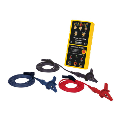
AEMC instruments PMR-1 User manual
AEMC instruments
AEMC instruments CA7028 User manual
AEMC instruments
AEMC instruments CA7027 User manual
AEMC instruments
AEMC instruments 4620 User manual

AEMC instruments
AEMC instruments 8510 User manual
AEMC instruments
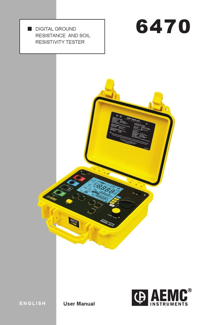
AEMC instruments 6470 User manual
AEMC instruments
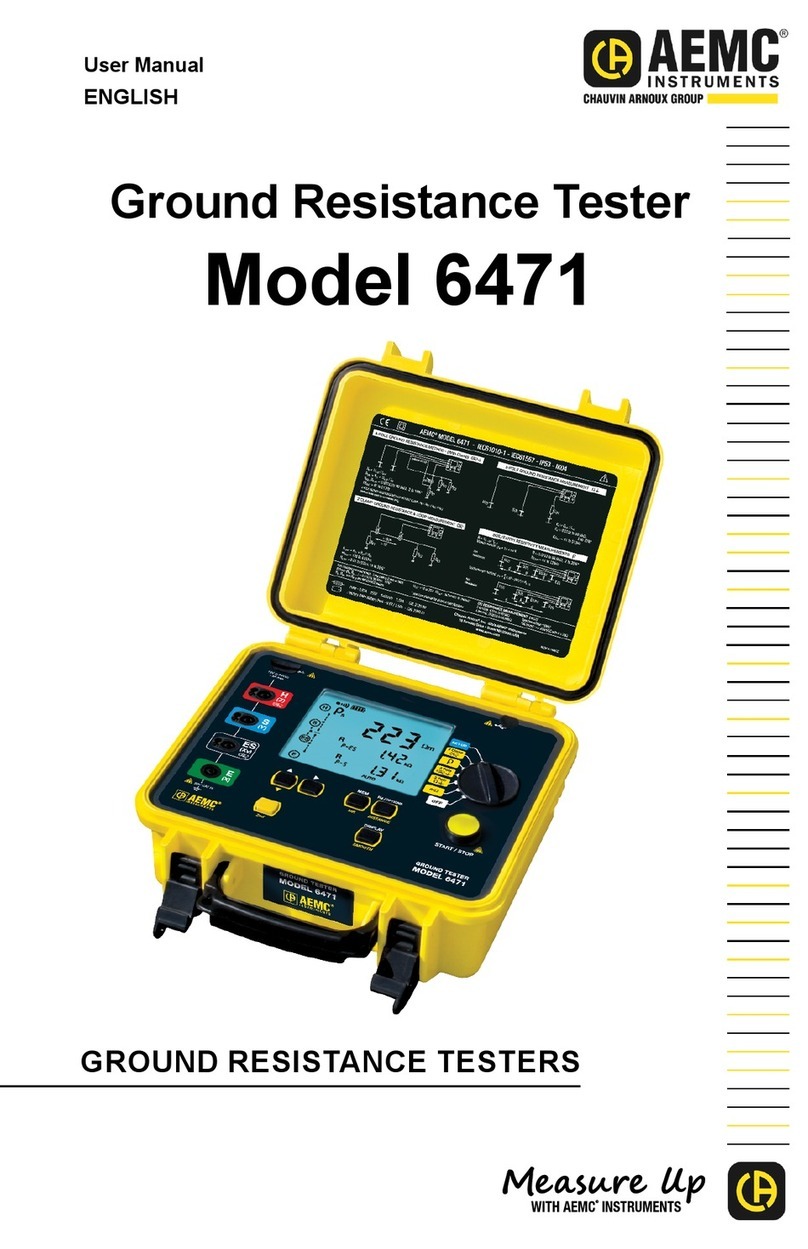
AEMC instruments 6471 User manual
AEMC instruments
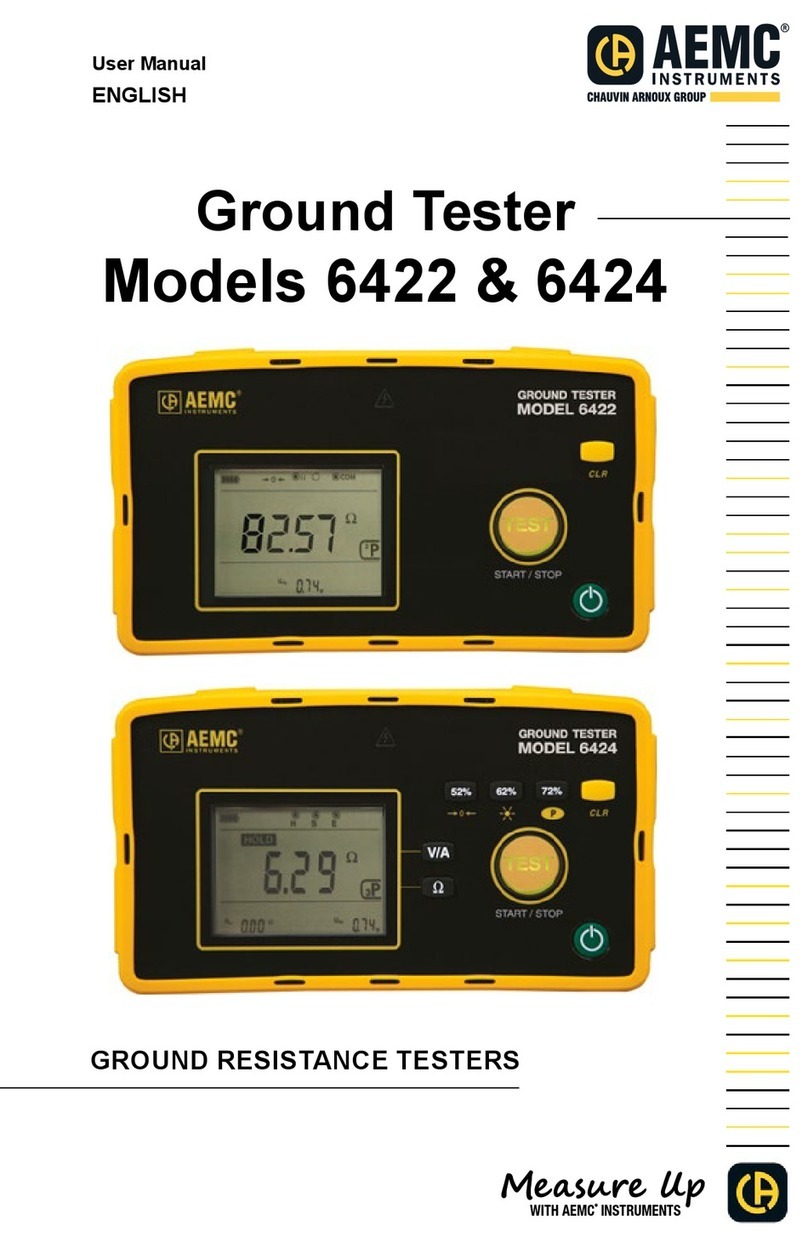
AEMC instruments 6422 User manual

AEMC instruments
AEMC instruments GROUNDFLEX 6474 User manual
AEMC instruments
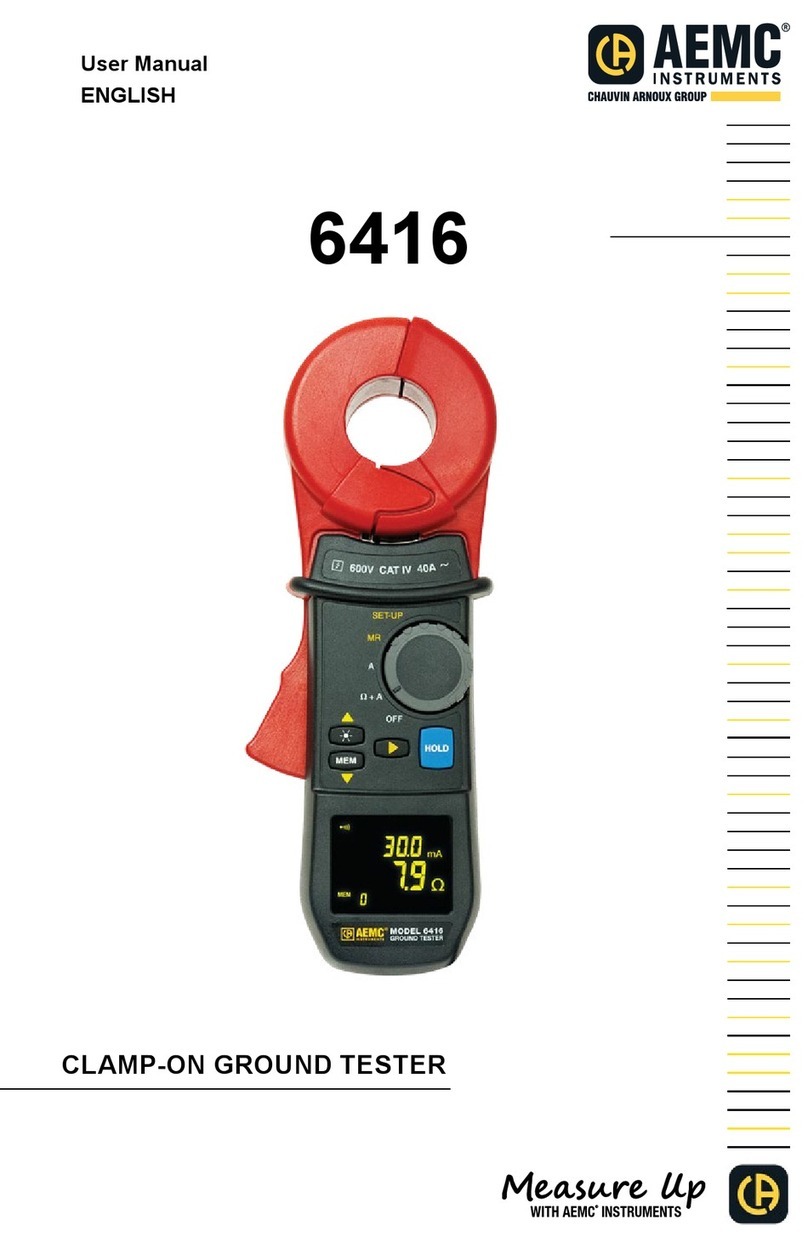
AEMC instruments 6416 User manual
