AEMC MR417 User manual

AC/DC Current Probe
Models MR417 & MR527
User Manual
ENGLISH
CURRENT PROBES
WITH AEMC
®
INSTRUMENTS

2 AC/DC Current Probes MR417 & MR527
Copyright©Chauvin Arnoux®, Inc. d.b.a. AEMC®Instruments. All rights reserved.
No part of this documentation may be reproduced in any form or by any means (including electronic
storage and retrieval or translation into any other language) without prior agreement and written consent
from Chauvin Arnoux®, Inc., as governed by United States and International copyright laws.
Chauvin Arnoux®, Inc. d.b.a. AEMC®Instruments
15 Faraday Drive • Dover, NH 03820 USA
Tel: (800) 945-2362 or (603) 749-6434 • Fax: (603) 742-2346
This documentation is provided “as is,” without warranty of any kind, express, implied, or otherwise.
Chauvin Arnoux®
but does not warrant the accuracy or completeness of the text, graphics, or other information contained
in this documentation. Chauvin Arnoux®, Inc. shall not be liable for any damages, special, indirect,
user of the documentation has been advised of the possibility of such damages.

AC/DC Current Probes MR417 & MR527 3
Statement of Compliance
Chauvin Arnoux®, Inc. d.b.a. AEMC® Instruments
using standards and instruments traceable to
international standards.
We guarantee that at the time of shipping your
The recommended calibration interval for this
instrument is 12 months and begins on the date of
receipt by the customer. For recalibration, please
use our calibration services. Refer to our repair and
calibration section at www.aemc.com.
Serial #:
Cata
Model #: MR417 / MR527
ll in the appropriate date as indicated:
Date Received:
Date Calibration Due:
Chauvin Arnoux®, Inc.
d.b.a AEMC®Instruments

4 AC/DC Current Probes MR417 & MR527
TABLE OF CONTENTS
5
1.1 PRECAUTIONS FOR USE .......................................................................... 6
1.2 RECEIVING YOUR SHIPMENT .................................................................. 7
1.3 ORDERING INFORMATION........................................................................ 7
1.3.1 Replacement Parts/Accessories ........................................................ 7
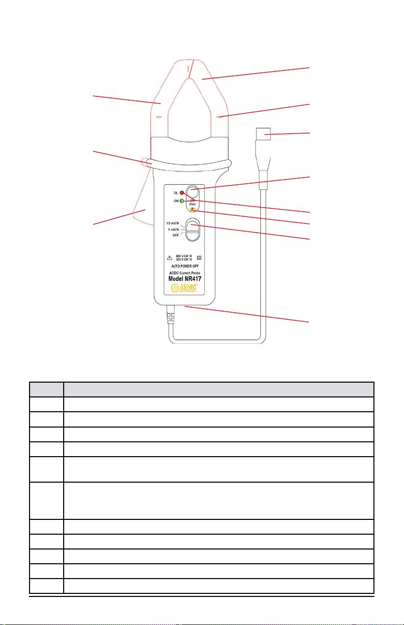
2.1 INTERFACE.................................................................................................. 9
2.1.1 MR417................................................................................................ 9
2.1.2 MR527.............................................................................................. 10
11
3.1 BATTERY INSTALLATION......................................................................... 11
3.2 EXTERNAL POWER (OPTIONAL)............................................................ 11
3.3 TURNING THE INSTRUMENT ON ........................................................... 12
3.4 AUTO STANDBY......................................................................................... 12
3.5 DC ZERO ADJUSTMENT .......................................................................... 12
3.6 MEASUREMENTS ..................................................................................... 13
3.6.1 Making a Measurement.................................................................... 13
3.6.2 Converting to Current....................................................................... 13
14
4.1 REFERENCE CONDITIONS ..................................................................... 14
4.2 ELECTRICAL SPECIFICATIONS.............................................................. 14
..................................... 14
.................................. 18
................................... 20
................................ 24
4.3 OPERATING LIMITS (MR417 AND MR527)............................................. 26
4.4 VARIATIONS IN THE RANGE OF USE.................................................... 27
4.5 POWER SUPPLY ....................................................................................... 28
4.6 ENVIRONMENTAL CONDITIONS ............................................................ 28
4.7 MECHANICAL SPECIFICATIONS ............................................................ 29
4.7.1 Housing Protection........................................................................... 31
4.8 SAFETY SPECIFICATIONS ...................................................................... 31
32
5.1 CLEANING.................................................................................................. 32
5.2 BATTERY REPLACEMENT....................................................................... 32
5.3 REPAIR AND CALIBRATION..................................................................... 33
5.4 TECHNICAL AND SALES ASSISTANCE ................................................. 33
5.5 LIMITED WARRANTY................................................................................ 34
5.5.1 Warranty Repairs ............................................................................. 34

AC/DC Current Probes MR417 & MR527 5
Thank you for purchasing an AEMC®Instruments Current Probe Model MR417 or
MR527. For best results from your instrument and for your safety, please read the
following operating instructions carefully and comply with the precautions for use.
This instrument is compliant with the IEC 61010-2-032 safety standards for voltages of
300 V in measurement Category IV or 600 V in Category III.
Indicates a WARNING. Whenever this symbol is
present, the operator must refer to the user manual before operation
Application or withdrawal authorized on conductors carrying dangerous voltages.
Type A current sensor as per IEC 61010-2-032
Battery
USB Socket
Indicates important information to acknowledge.
Direction of the current
The product has been declared recyclable
This product complies with the Low Voltage & Electromagnetic Compatibility
European directives (73/23/CEE & 89/336/CEE)
In the European Union, this product is subject to a separate collection system for
recycling electrical and electronic components in accordance with directive WEEE
2002/96/EC
CAT IV corresponds to measurements performed at the primary electrical
supply (< 1000 V).
Example: primary overcurrent protection devices, ripple control units, and
meters.
CAT III corresponds to measurements performed in the building installation at
the distribution level.
Example: hardwired equipment in xed installation and circuit breakers.
CAT II corresponds to measurements performed on circuits directly connected
to the electrical distribution system.
Example: measurements on household appliances and portable tools.

6 AC/DC Current Probes MR417 & MR527
These instructions are intended to ensure the safety of users and proper operation
of the instrument. Failure to observe these safety instructions may result in electric
The operator and/or the responsible authority must carefully read and clearly
understand the various precautions to take before and during use.
Do not use the instrument on networks on which the voltage or category
Observe the environmental conditions of use, including relative humidity,
altitude, degree of pollution, and place of use.
Do not use the instrument if it appears to be damaged, incomplete, or not
properly closed.
Before each use, check the condition of the insulation on the leads, housing,
and accessories. Any component on which the insulation is deteriorated (even
partially) must be set aside for repair or disposal.
Use suitable means of protection.
All troubleshooting and metrological checks must be performed by competent
and accredited personnel.

AC/DC Current Probes MR417 & MR527 7
Upon receiving your shipment, make sure that the contents are consistent with the
packing list. Notify your distributor of any missing items. It the equipment appears
at once, giving a detailed description of any damage. Save the damaged packing
container to substantiate your claim.
AC/DC Current Probe Model MR417
Includes 9 V battery, multi-language safety data sheet, and user manual
AC/DC Current Probe Model MR527
Includes 9 V battery, multi-language safety data sheet, and user manual
............................................

AC/DC Current Probes MR417 & MR527
The Models MR417 and MR527 are clamp-on current probes that measure DC
currents up to 1400 A, AC currents up to 1000 A (1400 A peak), and combined
They
indicate the shape and amplitude of the current measured in the form of a voltage.
These instruments can be used with oscilloscopes. They can be powered by a
battery or with 5 V via the optional micro-USB cable.
The MR417 and MR527 include the following features:
Range overage indicator.
Power supply indicator.
Zero adjustment.
Auto Standby feature.
Two ranges (sensitivity 1 and 10 mV/A).
Micro-USB connector to connect a power supply.

AC/DC Current Probes MR417 & MR527 9
Figure 1 (MR417)
Functions
1 Fixed (non-mobile) jaw
2
3 Male BNC connector
4DC Zero button
5OL (overload) and ON indicators. ON is green when Auto Standby is
enabled and yellow when it is disabled.
6P(Permanent mode) indicator. Holding down the DC Zero button while
turning ON the instrument enables Permanent mode. In this mode, Auto
Standby is disabled (see § 3.4).
7 3-position slide switch
8 USB port
9 Trigger
10 Hand guard
11 Mobile jaw
1
3
4
5
6
7
11
9
2

AC/DC Current Probes MR417 & MR527
Figure 2 (MR527)
Functions
1 Fixed (non-mobile) jaw
2
3 Male BNC connector
4DC Zero button
5OL (overload) and ON indicators. ON is green when Auto Standby is
enabled and yellow when it is disabled.
6P(Permanent mode) indicator. Holding down the DC Zero button while
turning ON the instrument enables Permanent mode. In this mode, Auto
Standby is disabled (see § 3.4).
7 3-position slide switch
8 USB port
9 Trigger
10 Hand guard
11 Mobile jaw
1
3
4
5
6
7
11
9
2

AC/DC Current Probes MR417 & MR527 11
NOTE: Before changing the battery, set the switch to OFF and remove the
clamp from the circuit being measured.
1. Using a screwdriver, remove the battery compartment cover (1) from the
back of the housing (see Figure 3).
2. Connect the battery to the snap-on connector (2), observing polarity.
3. Place the battery into the battery compartment (3).
4. Replace the battery compartment cover and screw it onto the housing.
Figure 3
For long-term measurements, you can connect the clamp to external power via any
micro-USB adapter that delivers 100 mA or more. If external power is disconnected,
the clamp automatically switches to battery operation.
The insulation between the type B micro-USB connector and the measurement
output is 600 V CAT III. This enables you to safely connect the clamp to measuring
instruments with uninsulated inputs. The type B micro-USB connector must not be in
contact with conductors or uninsulated parts at dangerous voltage.
When operating on external power, the Auto Standby feature is disabled. The color
of the ON indicator shows whether the automatic standby is enabled (green) or
disabled (yellow).

12 AC/DC Current Probes MR417 & MR527
To turn the clamp on, push the slide switch to the or setting:
MR417
corresponds to the 600 A range.
corresponds to the 60 A range.
MR527
corresponds to the 1400 A range.
corresponds to the 150 A range.
The green ON indicator should light up:
If the indicator blinks, less than 4 hours of battery life remains.
If the indicator does not light up, replace the battery (see § 5.2).
After 10 minutes of operation without user action (such as pressing the DC Zero
button), the clamp automatically enters Standby mode. In this mode, the ON indicator
will turn OFF.
To reactivate the clamp, press the DC Zero button or change the switch to any
setting other than OFF.
To disable automatic Standby, press and hold down DC Zero when turning the
instrument ON. The ON indicator blinks to indicate that the request has been applied.
The ON indicator will show steady yellow after you release the DC Zero button.
NOTE: If the measurement range (or sensitivity) is changed, the DC Zero
must be adjusted before any further measurements are made.
The DC Zero must be adjusted before any series of measurements and
after each disconnection and reconnection.
To adjust the DC Zero:
With the clamp connected to the measuring instrument, select the desired
measurement range (or sensitivity) on the switch.
Make sure that there is no conductor in the clamp and that its jaws are closed
correctly.
Press the DC Zero button.
The OL indicator will light up for approximately three seconds to indicate that the
zero adjustment is in progress.
The OL
If the OL indicator stays on, the zero could not be adjusted.
Before repeating the operation, check that the jaws closed correctly (air gaps
clean, no dust, no oxidation, etc.) and that there is no conductor in the clamp.
Press the DC Zero button again.
the last adjustment of the DC Zero that is kept.

AC/DC Current Probes MR417 & MR527 13
After adjusting the DC Zero:
1. Press the clamp trigger to open the jaws.
2. Clamp the jaws around the conductor to be measured. Use the centering marks
on the jaws to position the clamp around the conductor. If the measurement is
for a power calculation, ensure the arrow on the clamp jaws (see Figures 1 and
source load
3. Release the trigger, ensuring the jaws are completely and correctly closed.
4. Observe the measurements displayed on the measuring instrument.
5. If the OL indicator lights up, the current is too high to be measured. If the sliding
switch is set to the range, change the setting to .
Figure 4 (MR527 shown)
The MR417 and MR527 both provide two measurement ranges. The MR417
measures current up to 600 A with 1 mV of output corresponding to 1 A and
measures current up to 60 A with 10 mV corresponding to 1 A. The MR527 measures
current up to 1400 A with 1 mV corresponding to 1 A and measures current up to 150 A
with 10 mV corresponding to 1 A.
To convert the clamp output to current, divide the voltage reading on the connected
a reading of 100 mV corresponds to a current of 100 A.

14 AC/DC Current Probes MR417 & MR527
Temperature 73.4 °F ± 9 °F (23 °C ± 5 °C)
Relative humidity (20 to 75) % RH
Position of the conductor Centered on the marks on the jaws
Measurement frequency DC to 65 Hz sine wave
Zero
< 40 A/m
Zero
Input impedence
MR417
A
A
A
A
Intrinsic
uncertainty
MR527
A
A
A
A
Intrinsic
uncertainty
MR417
Phase shift
MR527
Phase shift

AC/DC Current Probes MR417 & MR527 15
MR417
MR527
Error (%)
Current (A)
Error (%)
Current (A)

16 AC/DC Current Probes MR417 & MR527
MR417
MR527
-15
-10
-5
0
110 100 1000
Error (%)
Current (A)
-10
-5
0
110 100 1000 10000
Error (%)
Current (A)

AC/DC Current Probes MR417 & MR527 17
MR417
MR527
Phase shift (°)
Current (A)
Current (A)
Phase shift (°)

AC/DC Current Probes MR417 & MR527
Insertion
impedance
MR417
MR527
Frequency (Hz)
Error (%)
Error (%)
Frequency (Hz)

AC/DC Current Probes MR417 & MR527 19
MR417
MR527
-60°
-50°
-40°
-30°
-20°
-10°
0°
10 100 1000 10000 100000
Phase shift (°)
Frequency (Hz)
-60°
-50°
-40°
-30°
-20°
-10°
0°
10 100 1000 10000 100000
Déphasage (°)
Phase shift (°)
Frequency (Hz)

AC/DC Current Probes MR417 & MR527
peak-to-peak
MR417
Intrinsic uncertainty
MR527
Intrinsic uncertainty
MR417
Phase shift
MR527
Phase shift
Other manuals for MR417
2
This manual suits for next models
1
Table of contents
Other AEMC Measuring Instrument manuals
Popular Measuring Instrument manuals by other brands

McCrometer
McCrometer SPI Mag 282L Installation, operation and maintenance manual

VOLTCRAFT
VOLTCRAFT LZG-1 operating instructions

MITECH
MITECH mt180 user manual

International Light Technologies
International Light Technologies CureRight ILT800 instruction manual

Extech Instruments
Extech Instruments SL130 user manual

MOS
MOS OPT100 instruction manual