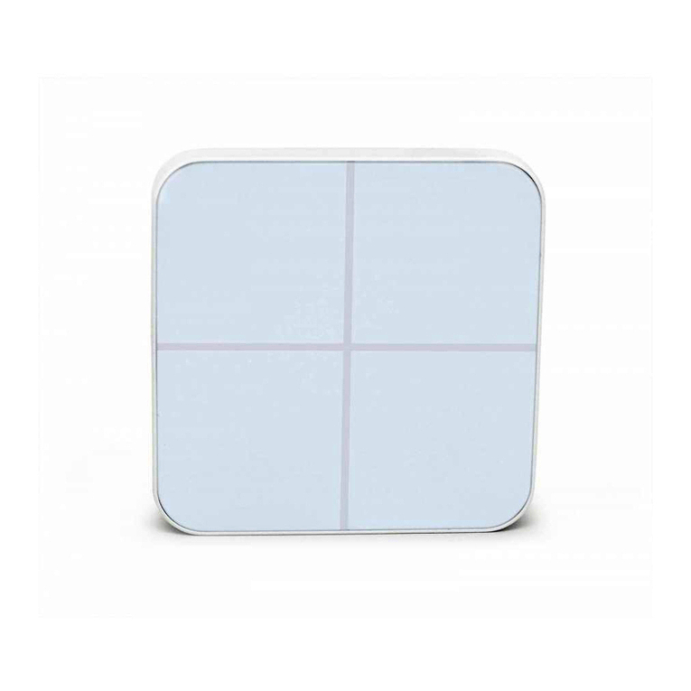
Aeotec WallMote User manual

29/10/2019 Aeotec Wallmote user guide : Aeotec Group
https://aeotec.freshdesk.com/support/solutions/articles/6000176572-wallmote-user-guide- 1/9
WallMote user guide.
Modified on: Thu, 14 Mar, 2019 at 4:18 PM
Aeotec WallMote.
Aeotec Wallmote has been crafted to control connected lighting using Z-Wave Plus (http://aeotec.com/z-wave-plus). It is
powered by Aeotec’s Gen5 (http://aeotec.com/z-wave-gen5) technology. You can find out more about Wallmote
(http://aeotec.com/z-wave-wireless-switch)by following that link.
To see whether Wallmote is known to be compatible with your Z-Wave system or not, please reference our Z-Wave
gateway comparison (http://aeotec.com/z-wave-gateways) listing. The technical specifications of Wallmote
(https://aeotec.freshdesk.com/solution/articles/6000176570-wallmote-technical-specification-) can be viewed at that link.
Familiarize yourself with your WallMote.
1. WallMote
2. Back-Mount plate
3. Double-sided tape
4. Micro USB cable

29/10/2019 Aeotec Wallmote user guide : Aeotec Group
https://aeotec.freshdesk.com/support/solutions/articles/6000176572-wallmote-user-guide- 2/9
Note: When the WallMote is placed on somewhere, keep the glass button surface upward direction and no other
physical surface or desktop contact with the glass button surface to avoid false triggering and battery consumption.
Effective Touch area for WallMote.
To further understand WallMote, it has a effective touch area for each available button. Any touch outside of the
effective touch area will not trigger the WallMote button.

29/10/2019 Aeotec Wallmote user guide : Aeotec Group
https://aeotec.freshdesk.com/support/solutions/articles/6000176572-wallmote-user-guide- 3/9
Important safety information.
Please read this and other device guides carefully. Failure to follow the recommendations set forth by Aeotec Limited
may be dangerous or cause a violation of the law. The manufacturer, importer, distributor, and / or reseller will not be
held responsible for any loss or damage resulting from not following any instructions in this guide or in other materials.
Keep product and batteries away from open flames and extreme heat. Avoid direct sun light or heat exposure. Improper
battery use may damage the product.
WallMote and WallMote Quad are intended for indoor use in dry locations only. Do not use in damp, moist, and / or wet
locations. Do not power permanently. Do not charge for more than 3 hours at a time. Do note apply permanent power.
Quick start.
Installing your WallMote.
1. Selecting a place or wall in your home to affix your WallMote Back Mount plate.
2. Using the Double-sided tape, wipe the two surfaces clean of any oil or dust with a damp towel. When the surface has
completely dried, peel one side of the tape back and attach it to the corresponding section on the rear side of the Back
Mounting Plate.

29/10/2019 Aeotec Wallmote user guide : Aeotec Group
https://aeotec.freshdesk.com/support/solutions/articles/6000176572-wallmote-user-guide- 4/9
Adding your WallMote to your Z-Wave network.
With your mounting plates prepared to hold each component of your WallMote, it’s time to add it to your Z-Wave
network.
1. Let your Z-Wave primary controller/gateway enter into pairing/
2. inclusion mode.
3. Take your WallMote near to your primary controller. Press the Action Button once on your WallMote, the LED will
blink with green color.
4. If your WallMote has been successfully added to your Z-Wave network, its green LED will be solid for 2 seconds and
then off. If the adding was unsuccessful and the red LED will be solid for 2 seconds and then off, repeat the above
steps.
With your WallMote now working as a part of your smart home, you’ll be able to configure it from your home control
software or phone application. Please refer to your software’s user guide for precise instructions on configuring the
WallMote to your needs.
Attach your WallMote to its Back Mounting plate.
With your WallMote added to the Z-Wave network. It’s now time to insert the main unit into the corresponding Back
Mount plate. Put the main unit in the top-left direction on the Back Mounting, and then push the WallMote into the Back
Mounting Plate, the WallMote will be attracted by the magnets on the Back Mount plate, as the figure below shows.

29/10/2019 Aeotec Wallmote user guide : Aeotec Group
https://aeotec.freshdesk.com/support/solutions/articles/6000176572-wallmote-user-guide- 5/9
Advanced Functions.
Send a wake up notification.
In order to send your WallMote new configuration commands from your Z-Wave controller or gateway, it will need to be
woken up.
Remove your WallMote unit from its Back Mounting Plate, press and hold the Action Button for 3 seconds (the buzzer
chirp once and the orange LED will be ON) on the back of the WallMote unit and then release it. This will trigger and
send a wake up notification command to your controller/gateway, then your WallMote will wake up for 10 minutes and
the orange LED will fast blink while it is awake (if the WallMote does not receive the Wake Up No More
Info from the primary Controller).
Removing your WallMote from a Z-Wave network.
Your WallMote can be removed from your Z-Wave network at any time. You'll need to use your Z-Wave network's main
controller/gateway. To do this, please refer to the part of their respective manuals that tell you how to remove devices
from your network.
1. Put your primary controller into device removal mode.
2. Unlock your WallMote from the Back Mount plate and take the WallMote unit near to your primary controller.
3. Press the Action Button on your WallMote.
4. If your WallMote is successfully removed from the Z-Wave network, the LED will become a colorful gradient for a
few seconds and then turn off. If the removing was unsuccessful, the red LED will be solid for 2 seconds and then turn
off, repeat the above steps.
Including WallMote as a non-secure device:
If you want your WallMote as a non-security device in your Z-wave network, you just need to press the Action Button
once on WallMote when you use a controller/gateway to add/include it.
The green LED will be on for 2 seconds and then the orange LED will fast blink for 10 minutes (if the WallMote does not
receive the Wake Up No More Info command from primary Controller) to indicate the inclusion is successful.
Including WallMote as a secure device:
In order to take full advantage of all functionality the WallMote, you may want your WallMote is a security device that
uses secure/encrypted message to communicate in Z-wave network, so a security enabled controller/gateway is
needed for the WallMote to be used as a security device.

29/10/2019 Aeotec Wallmote user guide : Aeotec Group
https://aeotec.freshdesk.com/support/solutions/articles/6000176572-wallmote-user-guide- 6/9
You need to press the WallMote Action Button 2 times within 1 second when your security controller/gateway starts the
network inclusion.
The blue LED will be on for 2 seconds and then the orange LED will fast blink for 10 minutes (if the WallMote does not
receive the Wake Up No
More Info command from primary Controller) to indicate the inclusion is successful.
Advanced Parameter Configurations.
Not all gateways will allow you to further configure your Z-Wave devices, but in the case that your gateway does allow
it, the WallMote has some available parameter configurations that will allow you to configure it further to your liking.
Touch beep
This will enable or disable the sound effects when you press or touch the sensing area. By default, this is
enabled.
Parameter 1 [1 byte]
0: Disable
1: Enable //default setting
Note: You can also enable or disable the sound effects via pressing and holding the Action Button for 12
seconds (the buzzer chirp once and the red LED will fast blink) and then release.
Touch vibration
This will enable or disable the vibration effects when you press or touch the sensing area. By default, this is
enabled.
Parameter 2 [1 byte]
0: Disable
1: Enable //default setting
Note: You can also enable or disable the vibration effects via pressing and holding the Action Button for 17
seconds (the buzzer chirp once and the red LED will be solid) and then release.
Button slide function
This will enable or disable the function of button slide.
Parameter 3 [1 byte]
0: Disable
1: Enable //Default Setting
WallMote Reports
This will allow you to configure what reports are sent when pressing WallMote Quads buttons.
Parameter 4 [1 byte]
1: Send Central Scene Command notification //Default Setting
3: Send Central Scene Command notification and Configuration Report.
Association table of the control buttons.
The WallMote supports 5 association groups, all control buttons can activate the configured scenes via sending the
Central Scene Notifications to primary controller/gateway (In association group 1). In order to use Association Groups,
make sure that your gateway or software can allow you to set these (ie: Vera Group Association Setup

29/10/2019 Aeotec Wallmote user guide : Aeotec Group
https://aeotec.freshdesk.com/support/solutions/articles/6000176572-wallmote-user-guide- 7/9
(https://aeotec.freshdesk.com/solution/articles/6000162165-using-wallmote-quad-with-vera-ui7)), in order to do so, please
refer to your gateways manual on setting group association. This will allow the WallMote to directly communicate
ON/OFF or Dimming commands to your devices without going through your gateway.
Every control button also can send the control commands to control the devices in the other association groups, see
the table below:
Dimmer control via sliding the button area.
The WallMote also supports sliding control, when the parameter 4 [1 byte] has been set to 3, you can slide up or down
on the button area to control a dimmer device by sliding up or down. Swiping up once will dim up a dimmer device by a
certain percentage, while swiping down once will dim down a dimmer device by a certain percentage.
This application is only suitable for Group Association control, it does not work with scene controls.
Your WallMote battery.

29/10/2019 Aeotec Wallmote user guide : Aeotec Group
https://aeotec.freshdesk.com/support/solutions/articles/6000176572-wallmote-user-guide- 8/9
Your WallMote has a internal rechargeable lithium battery that will allow you to charge it when it is in low battery. The
charger’s output should be a micro USB terminal with the specification of output DC 5V/1A. When the WallMote is in
charge state, the orange LED will be on. If the orange LED is off and the green LED remains on, then it indicates that
the battery charge is complete.
Note: When the WallMote is in low battery, you will see the orange LED will blink when you touch the control buttons.
Otherwise, if the blue LED blinks when touching the buttons, which means the battery is in normal level.
Waking up WallMote.
In order to configure WallMote, you must either (1) wake up WallMote using the below button press function.
1. Press and hold WallMote Action button
2. Wait until the RGB LED turns into a Yellow/Orange Color and beeps.
3. Release WallMote Action Button
The LED on WallMote will now rapidly blink its Yellow/Orange LED while it is in its awake state. You may send in any
configurations or commands from your current gateway to configure your WallMote.
4. Tap the Action Button on WallMote to put WallMote back to sleep, or wait 10 minutes. (recommended to manually put
it back to sleep to conserve battery life).
Testing Health Connectivity.
You can determine the health of your WallMotes connectivity to your gateway using a manual button press, hold, and
release function which is indicated by the LED color. This will help you maximize the battery life based on the health of
your WallMotes communication to your gateway. You'll be able to see a maximum battery use of 3 months of use over
green LED indication listed below.
1. Press and hold WallMote Action button
2. Wait until the RGB LED turns into a Purple Color
3. Release WallMote Action Button
The RGB LED will blink its Purple color while sending ping messages to your gateway, when it has finished, it will blink
1 of 3 colors:
Red = Bad Health
Yellow = Moderate Health
Green = Great Health
Be sure to watch for the blink, as it will only blink once very quickly.
Resetting your WallMote.
If at some stage, your primary controller is missing or inoperable, you may wish to factory reset your WallMote which
will remove it from its network that it is paired to, and reset all configured settings back to default. To do this, follow the
steps below:
1. Press and hold the Action button (20 seconds).
2. The LED should blink between green, purple, then red which will flash rapidly until a green LED becomes solid for 2
seconds to indicate a successful factory reset.
3. Let go of the Action Button.

29/10/2019 Aeotec Wallmote user guide : Aeotec Group
https://aeotec.freshdesk.com/support/solutions/articles/6000176572-wallmote-user-guide- 9/9
Further steps for different Z-Wave Gateways.
Most gateways will have specific steps to use WallMote Quad via group association (direct control), while others will
have different steps to use its scene triggers through the gateway directly for more advanced controls. Below are the
known steps required for the listed gateways.
1. SmartThings Hub (Custom Device Handler by Erocm123)
(https://aeotec.freshdesk.com/solution/articles/6000176961-using-aeotec-wallmote-with-smartthings-hub-)
2. Vera UI7 Group Association (https://aeotec.freshdesk.com/solution/articles/6000176960-using-wallmote-with-
vera-ui7-group-association-direct-control-)
If your gateway is not listed here, please contact support to see if there are possible steps that can be used on your
gateway to make it work.
Other manuals for WallMote
2
Table of contents
Other Aeotec Controllers manuals
Popular Controllers manuals by other brands

Rockwell
Rockwell powerflex 700h Programming manual

Morningstar
Morningstar SunGuard Operator's manual

oventrop
oventrop Hydromat DP DN 25 technical information

Carrier
Carrier 42EL Aqualia Installation, operation and maintenance instructions

braude
braude TANKMASTER MP Installation, operation and maintenance instructions

Planar
Planar Dome M2/PCI installation guide