Aeotec Smart Dimmer 6 User manual

View the expanded manual:
http://aeotec.com/support
Aeotec by Aeon Labs Smart Dimmer.
Aeotec Smart Dimmer 6 is a low-cost Z-Wave Dimmer
plug-in module specifically used to enable Z-Wave
command and control (on/off/dim) of any incandescent
bulbs, dimmable LED bulbs, halogen bulbs with or
without transformers. It can report immediate wattage
consumption or kWh energy usage over a period of
time. In the event of power failure, non-volatile memory
retains all programmed information relating to the unit’s
operating status.
Its surface has a Smart RGB LED, which can be used
for indicating the output load status or strength of the
wireless signal. You can congure its indication colour
according to your favour.
The Smart Dimmer 6 is a security Z-wave device and
supports Over The Air (OTA) feature for the products
rmware upgrade.
®
Familiarize yourself with your Smart Dimmer.
Getting your Smart Dimmer up and running is as simple
as plugging it into a wall socket and linking it to your
Z-Wave network. The following instructions tell you how
to add your Smart Dimmer to your Z-Wave network via
Aeotec by Aeon Labs’ Z-Stick or Minimote controller.
If you are using other products as your main Z-Wave
controller, such as a Z-Wave gateway, please refer to
the part of their respective manual that tells you how to
add new devices to your network.
If you’re using a Z-Stick:
Quick start. 1.
2.
3.
4.
5.
6.
7.
If you’re using a Minimote:
1. Decide on where you want your Smart Dimmer to be
placed and plug it in to a wall socket. Its RGB LED will
blink when you press the Action Button on the Smart
Dimmer.
Take your Minimote to your Smart Dimmer.
Press the Include button on your Minimote.
Press the Action Button on your Smart Dimmer.
If Smart Dimmer has been successfully added to your
Z-Wave network, its RGB LED will no longer blink.
If the adding was unsuccessful, the red LED will be
solid for 2 seconds and then remain colourful gradient
status, repeat the instructions from step 4.
Press any button on your Minimote to take it out of
inclusion mode.
With your Smart Dimmer now working as a part of your
smart home, you’ll be able to configure it from your
home control software. Please refer to your software’s
user guide for precise instructions on conguring Smart
Dimmer to your needs.
The colour of RGB LED will change according to the
output load power level when it is in Energy mode:
Version LED indication Output (W)
US
Green [0W, 180W)
Yellow [180W, 240W)
Red [240W, 300W)
AU
Green [0W, 345W)
Yellow [345W, 460W)
Red [460W, 575W)
You can also configure the brightness of RGB LED
when the Smart Dimmer is in Energy mode, Momentary
Indicate mode, or Night Light mode.
Your Smart Dimmer can be removed from your Z-Wave
network at any time.You’ll need to use your Z-Wave
network’s main controller to do this and the following
instructions which will tell you how to do this using an
Aeotec by Aeon Labs’Z-Stick or Minimote controller.
If you are using other products as your main Z-Wave
controller, please refer to the part of their respective
manuals that tells you how remove devices from your
network.
Removing your Smart Dimmer from a Z-Wave
network.
If you’re using a Z-Stick:
1.
2.
3.
4.
5.
6.
If your Z-Stick is plugged into a gateway or a
computer, unplug it.
Take your Z-Stick to your Smart Dimmer.
Press and hold the Action Button on your Z-Stick for 3
seconds and then release it.
Press the Action Button on your Smart Dimmer.
If your Smart Dimmer has been successfully
removed from your network, its RGB LED will remain
the colourful gradient status. If the removal was
unsuccessful, the RGB LED will be solid, repeat the
instructions from step 3.
Press the Action Button on the Z-Stick to take it out of
removal mode.
If you’re using a Minimote:
1.
2.
3.
4.
Take your Minimote to your Smart Dimmer.
Press the Remove Button on your Minimote.
Press the Action Button on your Smart Dimmer.
If your Smart Dimmer has been successfully
removed from your network, its RGB LED will remain
the colourful gradient status. If the removal was
Decide on where you want your Smart Dimmer to be
placed and plug it in to a wall outlet. Its RGB LED will
blink when you press the Action Button on the Smart
Dimmer.
If your Z-Stick is plugged into a gateway or a
computer, unplug it.
Take your Z-Stick to your Smart Dimmer.
Press the Action Button on your Z-Stick.
Press the Action Button on your Smart Dimmer.
If Smart Dimmer has been successfully added to your
Z-Wave network, its RGB LED will no longer blink.
If the adding was unsuccessful, the red LED will be
solid for 2 seconds and then remain colourful gradient
status, repeat the instructions from step 4.
Press the Action Button on the Z-Stick to take it out of
inclusion mode, and then return it to your gateway or
computer.
2.
3.
4.
5.
6.
Version LED indication Output (W)
EU
Green [0W, 345W)
Yellow [345W, 460W)
Red [460W, 575W)
Changing RGB LED mode.
You can change the mode of how the RGB LED acts
through configuring the Smart Dimmer. There are 3
different modes: Energy mode, Momentary indicate
mode, and Night light mode.
Energy mode will allow the LED to follow the state of
the Smart Dimmer, when the dimmer is on, the LED will
be on, and while the dimmer is off, the current colour
LED will be off and then the purple LED remains on.
Momentary indicate mode will momentarily turn the LED
on for 5 seconds then turn off after every state change
in the dimmer. Night light mode will allow the LED to be
turned on and off during your selected time of day you
have congured for it.
Parameter 81 [1 byte dec] is the parameter that will set
one of the 3 different modes. If you set this conguration
to:
(0) Energy Mode
(1) Momentary Indicate Mode
(2) Night Light Mode
Advanced functions.
Smart Dimmer 6
unsuccessful, the RGB LED will be solid, repeat the
instructions from step 2.
Press any button on your Minimote to take it out of
removal mode.
5.

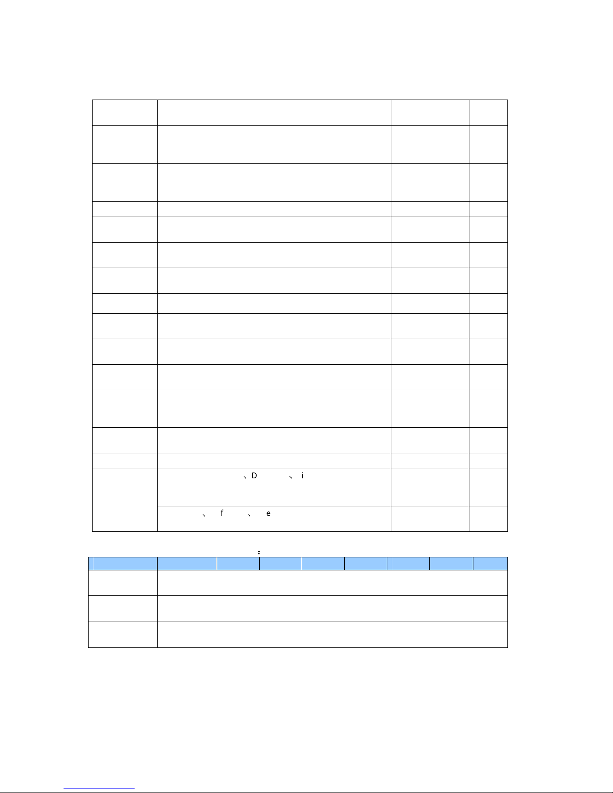
Model number: ZW099.
Max standby power: 0.8W.
USB output: DC 5V±5%, 1000mA.
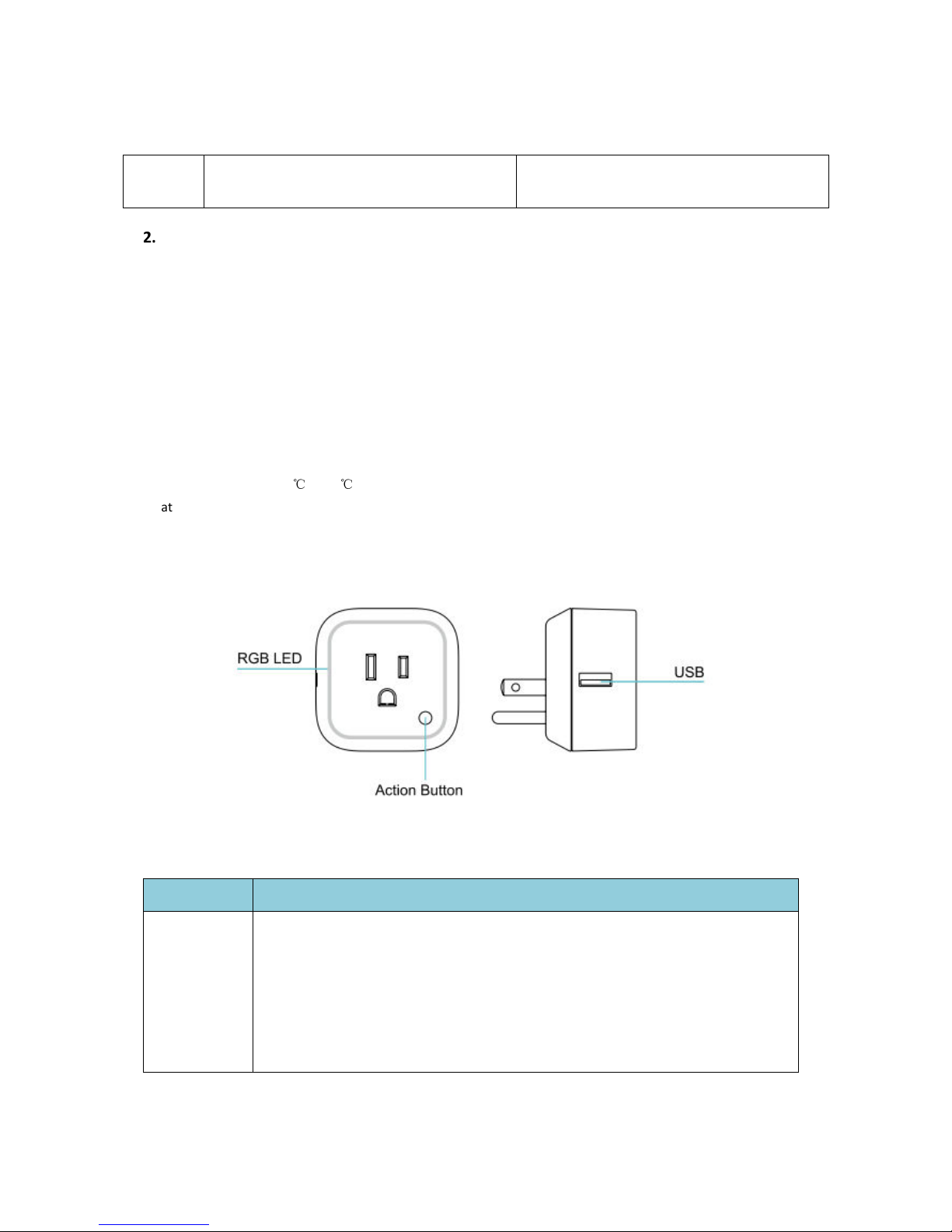
Operating temperature: 0 to 40 /32 to 104 .
Relative humidity: 8% to 80%.
Supported load type: Incandescent bulbs, dimmable
LED bulbs, halogen bulbs with or without transformers.
Operating distance: Up to 300 feet/100 meters outdoors.
AC input:
Technical specications.
C C F F
Version Input Working band
AU 230V 50Hz, Max: 2.5A 921.42MHz
BR 220V 60Hz, Max: 2.5A 921.42MHz
CN 220V 50Hz, Max: 2.5A 868.42MHz
EU 230V 50Hz, Max: 2.5A 868.42MHz
IL 230V 50Hz, Max: 2.5A 868.42MHz
IN 230V 50Hz, Max: 2.5A 865.22MHz
UK 230V 50Hz, Max: 2.5A 868.42MHz
US 120V 60Hz, Max: 2.5A 908.42MHz
6Warranty.
The "Warranty Period" begins on the date the Products
is delivered and continues for 12 months.
Any repairs under this warranty must be conducted by
an authorized Aeon Labs service representative and
under Aeon Labs' RMA policy. Any repairs conducted by
unauthorized persons shall void this warranty.
Excluded from the warranty are problems due to
accidents, acts of God, civil or military authority, civil
disturbance, war, strikes, fires, other catastrophes,
misuse, misapplication, storage damage, negligence,
electrical power problems, or modification to the
Products or its components.
Aeon Labs does not authorize any person or party to
assume or create for it any other obligation or liability in
connection with the Products except as set forth herein.
Aeon Labs will pass on to Customer all manufacturers’
Material warranties to the extent that they are
transferable, but will not independently warrant any
Material.
Customer must prepay shipping and transportation
charges for returned Products, and insure the shipment
or accept the risk of loss or damage during such
shipment and transportation. Aeon Labs will ship the
repaired or replacement products to Customer freight
prepaid.
Customer shall indemnify, defend, and hold Aeon
Labs and Aeon Labs' affiliates, shareholders,
directors, officers, employees, contractors, agents
and other representatives harmless from all demands,
claims, actions, causes of action, proceedings, suits,
assessments, losses, damages, liabilities, settlements,
judgments, nes, penalties, interest, costs and expenses
(including fees and disbursements of counsel) of
every kind (i) based upon personal injury or death or
injury to property to the extent any of the foregoing
is proximately caused either by a defective product
(including strict liability in tort) or by the negligent or
willful acts or omissions of Customer or its officers,
employees, subcontractors or agents, and/or (ii) arising
from or relating to any actual or alleged infringement or
misappropriation of any patent, trademark, mask work,
copyright, trade secret or any actual or alleged violation
of any other intellectual property rights arising from or
IN NO EVENT SHALL AEON LABS BE LIABLE FOR
ANY INDIRECT, INCIDENTAL, PUNITIVE, SPECIAL OR
CONSEQUENTIAL DAMAGES, OR DAMAGES FOR LOSS OF
PROFITS, REVENUE, OR USE INCURRED BY CUSTOMER OR
ANY THIRD PARTY, WHETHER IN AN ACTION IN CONTRACT,
OR TORT, OR OTHERWISE EVEN IF ADVISED OF THE
POSSIBILITY OF SUCH DAMAGES. AEON LABS' LIABILITY
AND CUSTOMER'S EXCLUSIVE REMEDY FOR ANY CAUSE OF
ACTION ARISING IN CONNECTION WITH THIS AGREEMENT
OR THE SALE OR USE OF THE PRODUCTS, WHETHER
BASED ON NEGLIGENCE, STRICT LIABILITY, BREACH OF
WARRANTY, BREACH OF AGREEMENT, OR EQUITABLE
PRINCIPLES, IS EXPRESSLY LIMITED TO, AT AEON LABS'
OPTION, REPLACEMENT OF, OR REPAYMENT OF THE
PURCHASE PRICE FOR THAT PORTION OF PRODUCTS
WITH RESPECT TO WHICH DAMAGES ARE CLAIMED. ALL
CLAIMS OF ANY KIND ARISING IN CONNECTION WITH THIS
AGREEMENT OR THE SALE OR USE OF PRODUCTS SHALL
BE DEEMED WAIVED UNLESS MADE IN WRITING WITHIN
THIRTY (30) DAYS FROM AEON LABS'S DELIVERY, OR THE
DATE FIXED FOR DELIVERY IN THE EVENT OF NONDELIVERY.
THE INDEMNITY AND WARRANTY IN ABOVE ARE EXCLUSIVE
AND IN LIEU OF ALL OTHER INDEMNITIES OR WARRANTIES,
WHETHER EXPRESS OR IMPLIED, INCLUDING THE IMPLIED
WARRANTIES OF MERCHANTABILITY AND FITNESS FOR A
PARTICULAR PURPOSE.
FCC NOTICE (for USA)
THE MANUFACTURER IS NOT RESPONSIBLE FOR ANY
RADIO OR TV INTERFERENCE CAUSED BY UNAUTHORIZED
MODIFICATIONS TO THIS EQUIPMENT.SUCH MODIFICATIONS
COULD VOID THE USER’S AUTHORITY TO OPERATE THE
EQUIPMENT.
STORE INDOORS WHEN NOT IN USE. SUITABLE FOR DRY
LOCATIONS. DO NOT IMMERSE IN WATER. NOT FOR USE
WHERE DIRECTLY EXPOSED TO WATER.
This device complies with Part 15 of the FCC Rules.
Operation is subject to the following two conditions:
This device may not cause harmful interference, and
This device must accept any interference received,
including interference that may cause undesired
operation. This equipment has been tested and found
to comply with the limits for a Class B digital device,
pursuant to part 15 of the FCC Rules. These limits are
designed to provide reasonable protection against
ha rmful interference in a residential installation. This
equipment generates, uses and can radiate radio
frequency energy and, if not installed and used in
accordance with the instructions, may cause harmful
interference to radio communications. However, there
is no guarantee that interference will not occur in a
particular installation. If this equipment does cause
harmful interference to radio or television reception,
which can be determined by turning the equipment
off and on, the user is encouraged to try to correct the
interference by one or more of the following measures:
1
2
Reorient or relocate the receiving antenna.
Increase the separation between the equipment and
receiver.
Connect the equipment into an outlet on a circuit
different from that to which the receiver is connected.
Consul the dealer or an experienced radio/TV
technician for help.
Do not dispose of electrical appliances as unsorted
municipal waste, use separate collection facilities.
Contact your local government for information
regarding the collection systems available.
Warning
Version:501009900001-X01 www.aeotec.com
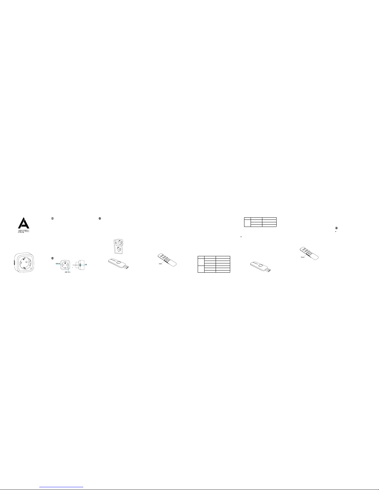
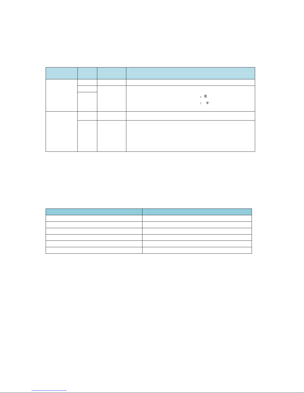
Reset your Smart Dimmer.
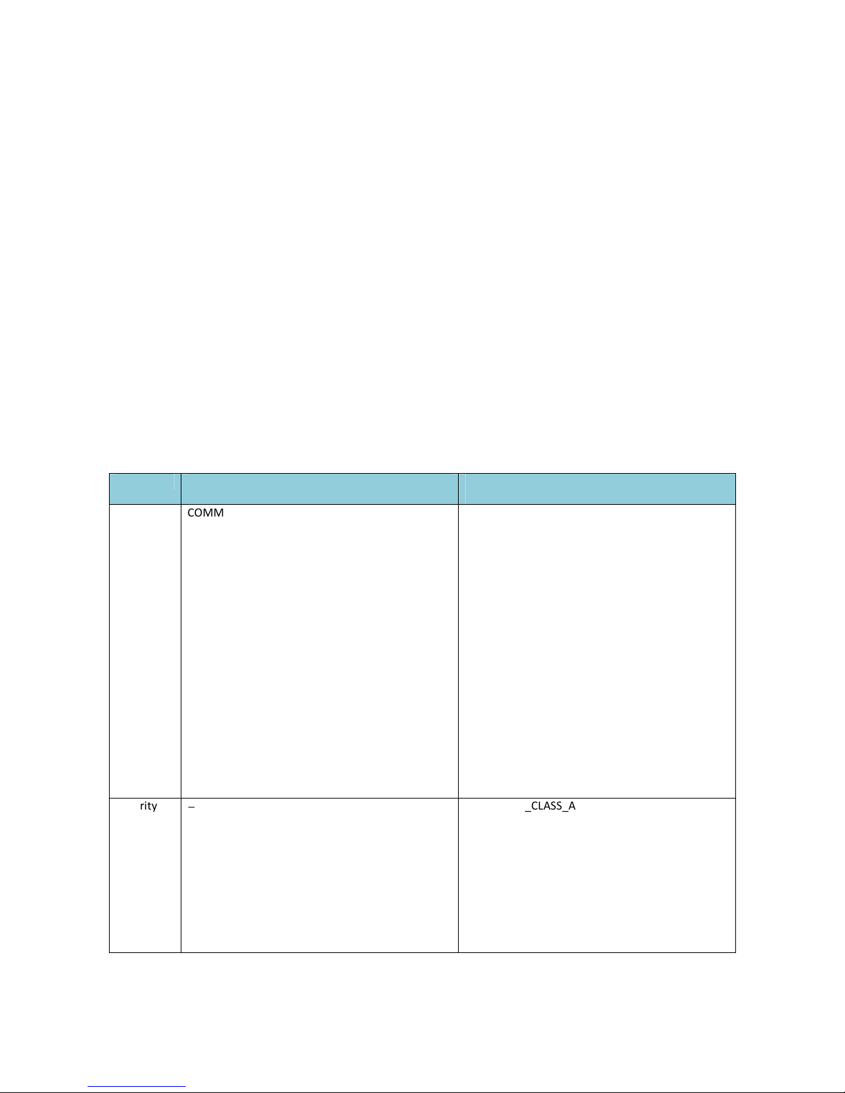
Security or Non-security feature of your Smart
Dimmer in Z-wave network.
If at some stage, your primary controller is missing or
inoperable, you may wish to reset all of your Smart
Dimmer’s settings to their factory defaults. To do this,
press and hold the Action Button for 20 seconds and
then release it. Your Smart Dimmer will now be reset to
its original settings, and the green LED will be solid for
2 seconds and then the RGB LED remains the colourful
gradient status as a conrmation.
If you want your Smart Dimmer as a non-security
device in Z-wave network, you just need to press the
Action Button once on Smart Dimmer when you use a
controller/gateway to add/include your Smart Dimmer.
In order to take full advantage of the Smart Dimmers
functionality, you may want your Smart Dimmer as a
security device that uses secure/encrypted message
to communicate in your Z-wave network, so a security
enabled controller/gateway is needed. You need to
press the Smart Dimmer’s Action Button 2 times within 1
second when your security controller/gateway starts the
network inclusion.
Aeon Labs warrants to the original purchaser of Products
that for the Warranty Period (as defined below), the
Products will be free from material defects in materials
and workmanship. The foregoing warranty is subject to
the proper installation, operation and maintenance of the
Products in accordance with installation instructions and
the operating manual supplied to Customer. Warranty
claims must be made by Customer in writing within thirty
(30) days of the manifestation of a problem. Aeon Labs'
sole obligation under the foregoing warranty is, at Aeon
Labs' option, to repair, replace or correct any such defect
that was present at the time of delivery, or to remove the
Products and to refund the purchase price to Customer.
in connection with the products, except to the extent
that such infringement exists as a result of Aeon Labs'
manufacturing processes.

Aeon Labs Smart Dimmer 6
Engineering Specifications and Advanced Functions for Developers
Aeon Labs Smart Dimmer is a Z-Wave multilevel switch device based on Z-Wave enhanced 232 slave library
V6. 1.06.
Its surface has the Smart RGB LEDs on, which can be used for indicating the output load status, the strength of
wireless signal. You can also configure its indication colour according to your favour.
It can be included and operated in any Z-wave network with other Z-wave certified devices from other
manufacturers and/or other applications. All non-battery operated nodes within the network will act as repeaters
regardless of vendor to increase reliability of the network.
It is also a security Z-wave device and supports the Over The Air (OTA) feature for the product’s firmware upgrade.
As soon as Smart Dimmer is removed from a z-wave network it will be restored into default factory setting.
1. Library and Command Classes
1.1 SDK 6. 1.06
1.2 Library
Basic Device Class:
BASIC_TYPE_ROUTING_SLAVE
Generic Device class:
GENERIC_TYPE_SWITCH_ MULTILEVEL
Specific Device Class:
SPECIFIC_TYPE_POWER_SWITCH_MULTILEVEL
1.3 Commands Class
Included Non
-
Secure
Network
Included Secure Network
Node Info
Frame
COMMAND_CLASS_ZWAVEPLUS_INFO V2
COMMAND_CLASS_SWITCH_MULTILEVEL V2
COMMAND_CLASS_COLOR_SWITCH
COMMAND_CLASS_MULTI_CHANNEL_V4
COMMAND_CLASS_MULTI_CHANNEL_ASSOCIATIO
N_V3
COMMAND_CLASS_METER V3
COMMAND_CLASS_SWITCH_ALL V1
COMMAND_CLASS_CONFIGURATION V1
COMMAND_CLASS_ASSOCIATION_GRP_INFO V1
COMMAND_CLASS_ASSOCIATION V2
COMMAND_CLASS_MANUFACTURER_SPECIFIC V2
COMMAND_CLASS_VERSION V2
COMMAND_CLASS_FIRMWARE_UPDATE_MD V2
COMMAND_CLASS_POWERLEVEL V1
COMMAND_CLASS_CLOCK V1
COMMAND_CLASS_MARK V1
COMMAND_CLASS_DEVICE_RESET_LOCALLY V1
COMMAND_CLASS_HAIL V1
COMMAND_CLASS_ZWAVEPLUS_INFO V2
COMMAND_CLASS_VERSION V2
COMMAND_CLASS_MANUFACTURER_SPECIFIC V2
COMMAND_CLASS_SECURITY V1
COMMAND_CLASS_MARK V1
COMMAND_CLASS_DEVICE_RESET_LOCALLY V1
COMMAND_CLASS_HAIL V1
Security
Command
Supported
Report
Frame
-
--
-
COMMAND_CLASS_ASSOCIATION_GRP_INFO V1
COMMAND_CLASS_SWITCH_MULTILEVEL V2
COMMAND_CLASS_SWITCH_ALL V1
COMMAND_CLASS_COLOR_SWITCH
COMMAND_CLASS_MULTI_CHANNEL_V4
COMMAND_CLASS_MULTI_CHANNEL_ASSOCIATIO
N_V3
COMMAND_CLASS_METER V3
COMMAND_CLASS_CONFIGURATION V1
COMMAND_CLASS_ASSOCIATION V2

COMMAND_CLASS_POWERLEVEL V
1
COMMAND_CLASS_CLOCK V1
COMMAND_CLASS_FIRMWARE_UPDATE_MD V2
2. Technical Specifications
Model number: ZW099
Operating distance: Up to 300 feet/100 meters outdoors.
Input: 120V~, 60Hz. (USA Version)
230V~, 0Hz. (EU, AU, CN Version)
230V~, 60Hz. (BR version)
Output: 120V~, 60Hz, Max 2. A Resistor load. (USA Version)
230V~, 0Hz, Max 2. A Resistor load. (EU Version)
230V~, 0Hz, Max 2. A Resistor load. (CN Version)
230V~, 0Hz, Max 2. A Resistor load. (AU Version)
230V~, 60Hz, Max 2. A Resistor load. (BR Version)
Operating temperature: 0 to 40 .
℃ ℃
Relative humidity: 8% to 80%.
3. Familiarize yourself with your Smart Switch
3.1 Interface
4. All functions of each trigger
4.1 Function of Action Button
Trigger
Description
Short
press
one time
1. Send non
-
security Node Info frame.
2. Add Smart Dimmer into a z-wave network
1. Insert the Smart Dimmer to power socket, The RGB LED will be colorful gradient status.
2. Let the primary controller into inclusion mode (If you don’t know how to do this, refer to
its manual).
3. Press the Action button.
4. If the inclusion success, Smart Dimmer LED will be solid. Otherwise, the LED will remain
colorful gradient status, in which you need to repeat the process from step 2.

3.
Remove
Smart Di
mmer
from a z
-
wave network
1. Insert the Smart Dimmer to power socket, The Smart Dimmer LED will be solid.
2. Let the primary controller into remove mode (If you don’t know how to do this, refer to
its manual).
3. Press the Action button.
4. If the remove is successful, Smart Dimmer LED will be colorful gradient status. If Smart
Dimmer LED still be solid, please repeat the process from step 2.
Short press 2
times
1.
Send Security Node Info frame
.
2. Add Smart Dimmer into a z-wave network
1. Insert the Smart Dimmer to power socket, The LED will be colorful gradient status.
2. Let the primary controller into inclusion mode (If you don’t know how to do this, refer to
its manual).
3. Press the Action Button.
4. If the inclusion success, Smart Dimmer LED will be solid. Otherwise, the LED will remain
colorful gradient status, in which you need to repeat the process from step 2.
3. Remove Smart Dimmer from a z-wave network
1. Insert the Smart Dimmer to power socket, The Smart Dimmer LED will be solid.
2. Let the primary controller into remove mode (If you don’t know how to do this, refer to
its manual).
3. Press the Action button.
4. If the remove success, Smart Dimmer LED will be colorful gradient status. If Smart
Dimmer LED still be solid, please repeat the process from step 2.
Press and hold
20 seconds
Reset
Smart Dimmer
to factory Default
1. Make sure the Smart Dimmer has been connected to the power supply.
2. Press and hold the Z-wave button for 20 seconds.
3. If holding time more than one second, the LED will blink faster and faster. If holding time
more than 20seconds, the green LED will be on for 2 seconds and then remain colorful
gradient status, it indicates reset success, otherwise please repeat step 2.
Note
1, This procedure should only be used when the primary controller is inoperable.
2, Reset Smart Dimmer to factory default settings will:
a), exclude the Smart Dimmer from Z-Wave network;
b), delete the Association setting, power
measure value, Scene Configuration settings and
restore the Configuration settings to their defaults.
4.2 RGB LED indication when Smart Dimmer is in Energy Mode

4.3 RGB LED indication when Smart Dimmer is in Wireless Power level Test Mode
5. Special rule of each command
5.1
Z-Wave Plus Info Report Command Class
Parameter
Value
Z-Wave Plus Version 1
Role Type (ZWAVEPLUS_INFO_REPORT_ROLE_TYPE_SLAVE_ALWAYS_ON)
Node Type 0 (ZWAVEPLUS_INFO_REPORT_NODE_TYPE_ZWAVEPLUS_NODE)
Installer Icon Type 0x0600 (ICON_TYPE_GENERIC_LIGHT_DIMMER_SWITCH)
User Icon Type 0x0600 (ICON_TYPE_GENERIC_LIGHT_DIMMER_SWITCH)
5.2 Basic Command Class
Basic Set=0x01 to 0x63 or 0xFF, turn ON output load.
Basic Set=0x00, turn OFF output load.
RGB RGB indication Status
RGB LED Purple color (10%) Output load is turned off.
Green Output load is in small wattage range.
US version
,
the range of load wattage is [0W, 180W)
AU version
,
the range of load wattage is [0W, 34 W)
EU version
,
the range of load wattage is [0W, 34 W)
Yellow Output load is in big wattage range.
US version
,
the range of load wattage is [180W, 240W)
AU version
,
the range of load wattage is [34 W, 460W)
EU version
,
the range of load wattage is [34 W, 460W)
Red Output load is in warning wattage range.
US version
,
the range of load wattage is [240W,300W)
AU version
,
the range of load wattage is [460W, 7 W)
EU version
,
the range of load wattage is [460W, 7 W)
RGB RGB indication Status
RGB LED Purple LED fast blink Enter into the wireless power level test mode
Green LED is switched to ON state
for 2 seconds
wireless power level is good
Yellow LED is switched to ON state
for 2 seconds
wireless power level is acceptable but latency can occur
Red LED is switched to ON state for
2 seconds
wireless power level is insufficient

5.3 Association Command Class
Smart Dimmer supports 2 association groups and Max nodes for each group.
Association
Group
Nodes
Send Mode
Send commands
Group 1 0 N/A N/A
1 Single Cast When the state of Smart Dimmer(on/off/dim the load ) is changed:
1, Set Configuration parameter 80 to 0
:
Reserved (Default).
2, Set Configuration parameter 80 to 1
:
Send Hail CC.
3. Set Configuration parameter 80 to 2: Send the Basic Report.
[2, ]
Group 2 0 N/A N/A
[1, ] Single Cast Forward the Basic Set, Switch Multilevel Start Level Change, Switch
Multilevel Stop Level Change, Switch Multilevel Set to associated
nodes in Group 2 when the Smart Dimmer receives the Basic Set,
Switch Multilevel Start Level Change, Switch Multilevel Stop Level
Change, Switch Multilevel Set commands from main controller.
5.4 Association Group Info Command Class
5.4.1 Association Group Info Report Command Class
Profile: General: NA (Profile MSB=0, Profile LSB=0)
5.4.2 Association Group Name Report Command Class
Group 1: Lifeline
Group 2: Retransmit
5.5 M
anufacturer Specific Report
Parameter Value
Manufacturer ID 1 US/EU/AU=0x00 CN=0x01
Manufacturer ID 2 US/EU/AU=0x86 CN=0x6A
Product Type ID 1 EU=0x00, US=0x01, AU=0x02 CN=0x1D (29)
Product Type ID 2 0x03
Product ID 1 0x00
Product ID 2 0x63 (99)
5.6 Multilevel Switch Command Class
The Multilevel Switch CC is used to change the state/brightness level of output load.
5.7 Multi Channel Command Class
Multi Channel CC encapsulates the Multilevel Switch CC, Z-wave plus info CC, Association Group info CC,
Association CC and supports 2 endpoints.
Multi Channel encapsulation Multilevel Switch CC of endpoint 1 is used to Set/Get the state of output load.
Multi Channel encapsulation Multilevel Switch CC of endpoint 2 is used to Set/Get the brightness level of RGB
LED when it is in Night light mode.
5.8 Color Switch Command Class
Supported color component: Red (02), Green (03), Blue (04).
Color Switch Set is used to change the color of RGB Led only in Night light mode.

5.9 Configuration Set Command Class
7
6
4
3
2
1
0
Command Class = COMMAND_CLASS_CONFIGURATION
Command = CONFIGURATION_SET
Parameter Number
Default
Reserved
Size
Configuration Value 1(MSB)
Configuration Value 2
………
Configuration Value n(LSB)
Parameter Number Definitions (8 bit):
Parameter
Number
Hex / Decimal
Description
Default Value
Size
0x03 (3) Current Overload Protection. Output Load will be turned off
automatically when the Current overrun 2.6A and the time
more than 2 minutes (0=disabled, 1=enabled).
0 1
0x14 (20) Configure the output load status after re-power on
(0=last status, 1=always on, 2=always off)
0 1
0x21 (33) Set the RGB LED color value for testing.
Value1: Reserved
Value2: Red value
Value3: Green value
Value4: Blue value
- 4
0x 0 (80) Enable to send notifications to associated devices (Group 1)
when the state of Smart Dimmer’s load changed
(0=nothing, 1=hail CC, 2=basic CC report).
0 1
0x 1 (81) Configure the state of LED when it is in 3 modes below:
0= Energy mode, the LED will follow the status (on/off) of
its load.
1= Momentary indicate mode, when the state of Dimmer’s
load changed, The LED will follow the status (on/off) of its
load, but the red LED will turn off after seconds if there is
no any switch action.
2= Night light mode.
0 1
0x 3 (83) Configure the RGB value when it is in Night light mode.
Value1: Red color value
Value2: Green color value
Value3: Blue color value
Value1=0x1B
Value2=0x14
Value3=0x1B
3
0x 4 (84) Configure the brightness level of RGB LED (0%-100%) when
it is in Energy Mode/momentary indicate mode.
Value1: green color value.
Value2: yellow color value.
Value3: red color value.
Green= 0
Yellow= 0
Red= 0
3

0x A (90) Enables/disables parameter 91 and 92 below (1=enabled,
0=disabled).
0 1
0x B (91) The value here represents minimum change in wattage (in
terms of wattage) for a REPORT to be sent (Valid values 0-
60000).
2 (W) 2
0x C (92) The value here represents minimum change in wattage
percent (in terms of percentage) for a REPORT to be sent
(Valid values 0-100).
(%) 1
0x64 (100) Set 101-103 to default. N/A 1
0x6 (101) Which reports need to send in Report group 1 (See flags in
table below).
0x00 00 00 00 4
0x66 (102) Which reports need to send in Report group 2 (See flags in
table below).
0x00 00 00 00 4
0x67 (103) Which reports need to send in Report group 3 (See flags in
table below).
0x00 00 00 00 4
0x6E (110) Set 111-113 to default. N/A 1
0x6F (111) The time interval of sending Report group 1 (Valid values
0x01-0x7FFFFFFF).
0x00 00 02 58
4
0x70 (112) The time interval of sending Report group 2 (Valid values
0x01-0x7FFFFFFF).
0x00 00 02 8 4
0x71 (113) The time interval of sending Report group 3 (Valid values
0x01-0x7FFFFFFF).
0x00 00 02 8 4
0xC8 (200) Partner ID
(0= Aeon Labs Standard Product,
1= others).
0 1
0xFC (2 2) Enable/disable Configuration Locked (0 =disable, 1 =
enable).
0 1
0xFE (2 4) Device Tag. 0 2
0xFF (2 ) 1, Value=0x
、
Default=1
、
Size=4
Reset to factory default setting and removed from the z-
wave network
N/A 4
2, Value=0
、
Default=1
、
Size=1
Reset to factory default setting
N/A 1
Configuration Values for parameter 101-103
:
7 6 4 3 2 1 0
configuration
Value 1(MSB)
Reserved
configuration
Value 2
Reserved
configuration
Value 3
Reserved

configuration
Value 4(LSB)
Reserved
Reserved
Reserved
Reserved
Auto
send
Meter
REPORT
(for
kWh) at
the
group
time
interval
Auto
send
Meter
REPOR
T (for
watt)
at the
group
time
interval
Auto
send
Meter
REPORT
(for
current)
at the
group
time
interval
Auto
send
Meter
REPOR
T (for
voltage
at the
group
time
interval
Example:
a. Automatically report Meter CC (Watts) to node "1" every 12 minutes
1. Enable sending Meter CC (Watts) automatically in report group 1
ZW_SendData(0x70, 0x04, 0x6 , 0x04, 0x00,0x00,0x00,0x04);
2. Set the interval of sending Meter CC (Watts) in report group 1
ZW_SendData(0x70, 0x04, 0x6F, 0x04, 0x00,0x00,0x02,0xd0);
3. Associate to node "1"
ZW_SendData(0x8 , 0x01, 0x01, 0x01);
b. Set default values
ZW_SendData(0x70, 0x04, 0x2 ,0x01,0x00);
Table of contents
Other Aeotec Dimmer manuals
Popular Dimmer manuals by other brands

retrotouch
retrotouch RTS2030 instruction manual

AMX
AMX Single Channel Lutron FDB Ballast Dimmer... Installation sheet

SMART
SMART DIMension 3K Installation and operation manual

LightwaveRF
LightwaveRF JSJS LW250 Operation manual

EUCHIPS
EUCHIPS Walldim103 quick start guide

Lutron Electronics
Lutron Electronics Energi TriPak Series Quick start quide