PAW HeatBloC K38 DN 25 Owner's manual

PAW GmbH & Co. KG
Böcklerstr. 11, 31789 Hameln - Germany
Phone: +49-5151-9856-0, Fax: +49-5151-9856-98
E-mail: info@paw.eu, Web: www.paw.eu
2020/04 993x083x-mub-en – V04 1
DN 25
DN 32
Installation and Operation Instructions
HeatBloC®K38
DN 25 / DN 32

1General Information
2 993x083x-mub-en – V04 2020/04
Item no. 993x083x-mub-en - Version V04 – Issued 2020/04
Translation of the original instructions
We reserve the right to make technical changes without notice!
Printed in Germany – Copyright by PAW GmbH & Co. KG
PAW GmbH & Co. KG
Böcklerstraße 11
31789 Hameln - Germany

1General Information
2020/04 993x083x-mub-en – V04 3
Contents
1General Information.....................................................................................................4
1.1 Scope of these instructions ..........................................................................................4
1.2 Designated use ............................................................................................................4
2Safety instructions .......................................................................................................5
3Product description......................................................................................................6
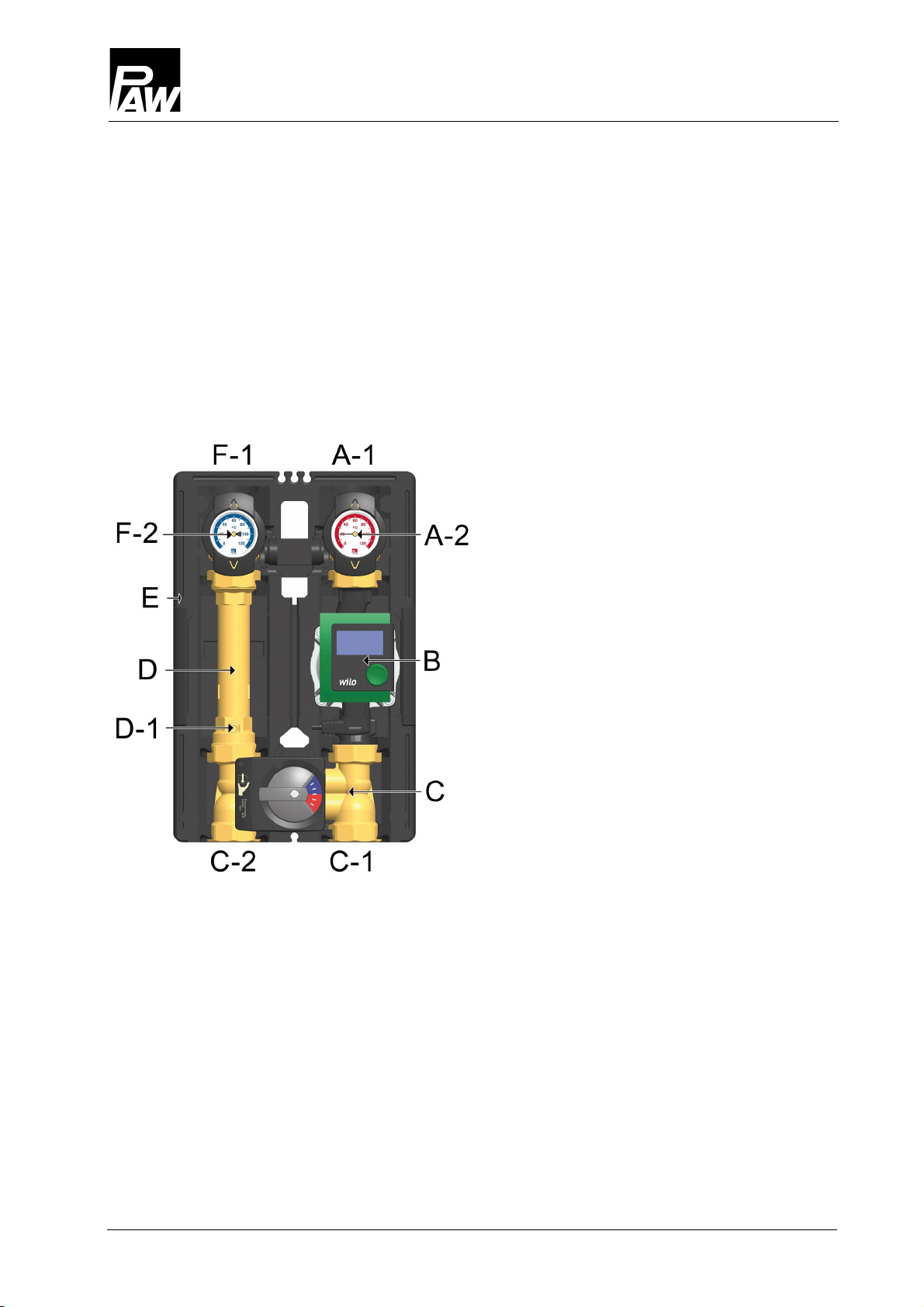
3.1 Equipment....................................................................................................................6
3.2 Function .......................................................................................................................7
3.3 Mixing valve [specialist]................................................................................................8
3.4 Accessories: Actuator (optional)...................................................................................9
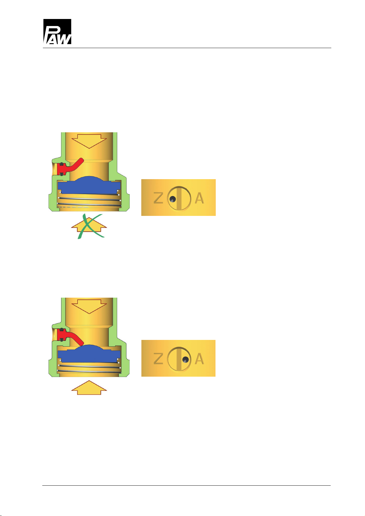
3.5 Flow check valve [specialist] ......................................................................................10
4Assembly and installation [specialist]........................................................................... 11
4.1 Installation and commissioning of the HeatBloC®.......................................................11
5Scope of delivery [specialist]....................................................................................... 13
5.1 Spare parts DN 25......................................................................................................14
5.2 Spare parts DN 32......................................................................................................16
6Technical data........................................................................................................... 18
6.1 Pressure drop and pump characteristic curves DN 25................................................ 19
6.2 Pressure drop and pump characteristic curves DN 32................................................19
7Disposal ................................................................................................................... 20

1General Information
4 993x083x-mub-en – V04 2020/04
1General Information
Carefully read these instructions before installation and commissioning.
Save these instructions in the vicinity of the installation for future reference.
1.1 Scope of these instructions
These instructions describe the installation, commissioning, function and the operation of
the mixed HeatBloC®K38 DN 25 and DN 32.
For other components of the installation, such as the pump, the controller or the modular
distribution manifold, please observe the instructions of the corresponding manufacturer.
The chapters called [specialist] are intended for specialists only.
1.2 Designated use
The HeatBloC®may only be used in heating circuits taking into consideration the technical
limit values indicated in these instructions.
The HeatBloC®must not be used in drinking water applications.
Improper usage of the HeatBloC®excludes any liability claims.
This product complies with the relevant directives and is therefore labelled with the CE mark.
The Declaration of Conformity is available upon request, please contact the manufacturer.
Only use PAW accessories with the HeatBloC®.
The wrapping materials are made of recyclable materials and can be disposed of with
recyclable materials.

2Safety instructions
2020/04 993x083x-mub-en – V04 5
2Safety instructions
The installation and commissioning as well as the connection of electrical components require
technical knowledge commensurate with a recognised vocational qualification as a fitter for
plumbing, heating and air conditioning technology, or a profession requiring a comparable level
of knowledge [specialist].
The following must be observed during installation and commissioning:
•relevant local and national regulations
•accident prevention regulations of the professional association
•instructions and safety instructions of this manual
CAUTION
Personal injury and damage to property!
The HeatBloC®must only be used in heating circuits filled with
heating water according to VDI 2035 / Ö-Norm H 5195-1.
The HeatBloC®must
not
be used in drinking water applications.
NOTICE
Material damage due to mineral oils!
Mineral oil products cause lasting damage to seals made of EPDM, whereby the sealant
properties get lost. We do not assume liability nor provide warranty for damage to property
resulting from sealants damaged in this way.
It is imperative to avoid that EPDM gets in contact with substances containing
mineral oils.
Use a lubricant based on silicone or polyalkylene and free from mineral oils,
such as Unisilikon L250L and Syntheso Glep 1 of the Klüber company or a
silicone spray.

3Product description
6 993x083x-mub-en – V04 2020/04
3Product description
The HeatBloC®K38 is a preassembled group of fittings for heating circuits.
The PAW HeatBloC®is designed such that it can be directly mounted onto a PAW distribution
manifold or a mounting plate with thread connections.
3.1 Equipment
A-1 Flow to the consumer circuit
A-2
Full metal thermometer
with immersion sleeve, integrated
in the ball valve (flow)
B Heating pump
C 4-way mixing valve
C-1 Flow from the heat generator
C-2 Return to the heat generator
D-1 Check valve
D Return pipe
E Design insulation
with optimised function
F-2 Full metal thermometer
with immersion sleeve, integrated
in the ball valve (return)
F-1 Return from the consumer circuit

3Product description
2020/04 993x083x-mub-en – V04 7
3.2 Function
K38 – with 4-way mixing valve
K38 allows to keep up the boiler return temperature
and to maintain a minimum boiler flow rate
(with boiler circuit pump). A part of the flow water from
the boiler is mixed into the return from the consumers,
depending on the adjustment of the mixing valve.
A boiler circuit pump is usually necessary.
When K38 is mounted on a distribution manifold,
a boiler circuit pump is mandatory. In this case the
4-way mixing valve serves as a hydraulic separator
(depending on the adjustment of the mixing valve).
Application range:
•for heating systems controlled by a mixing
valve in combination with a boiler temperature
maintenance
•to maintain a minimum boiler flow rate

3Product description
8 993x083x-mub-en – V04 2020/04
3.3 Mixing valve [specialist]
Mixing valve position 0
Mixing valve position 5
Mixing valve position 10

3Product description
2020/04 993x083x-mub-en – V04 9
3.4 Accessories: Actuator (optional)
The PAW actuator for weather-compensated control is available as an accessory.
For mixing valves with flow on the left, the scale must be turned by 180°.
for mixing valve with flow on the right for mixing valve with flow on the left
Assembly of the actuator for
mixing valve with flow on the right:
If the PAW actuator has been purchased
as an optional accessory, the mixing
valve contains a metal plate. To mount
the PAW actuator on the mixing valve,
proceed as follows:
1. Turn the rotary knob of the mixing
valve into position
0
(fig. 4).
2. Set the actuator to manual mode
by turning the selector switch (fig. 3).
3. Turn the rotary knob of the actuator
to the left to the position shown on
the adjacent figure (fig. 3).
4. Mount the rotation lock / the stop bolt in
the
left
opening of the metal plate (fig.
4). The actuator is fixed on a stop bolt.
5. Put the PAW actuator on the rotary
knob of the mixing valve and mount
the actuator on the stop bolt. The
PAW actuator must be mounted in a
horizontal position as shown in fig. 5.
6. Set the actuator to automatic mode.
Fig. 1
Fig. 2
Fig. 3
Fig. 4
Fig. 5
blue blue
blue
red red
Selector
switch
Stop bolt

3Product description
10 993x083x-mub-en – V04 2020/04
3.5 Flow check valve [specialist]
The HeatBloC®K38 is equipped with a check valve (D-1) in the return pipe.
The check valve can be opened. The opening pressure is 200 mm wc.
Operation
During operation, the marking must be directed to "Z".
The check valve is closed.
Flow only in the direction of the arrow.
Filling, draining, venting
For filling, draining and venting the installation, the marking
must be directed to "A".
The check valve is open.
Flow in both directions

4Assembly and installation [specialist]
2020/04 993x083x-mub-en – V04 11
4Assembly and installation [specialist]
The HeatBloC®K38 can be mounted on a PAW modular distribution manifold or on a wall
bracket. The modular distribution manifold and the wall bracket are optional accessories and
are thus not included in the scope of delivery.
NOTICE
Damage to property!
The location of installation must be dry, load-carrying, frost-proof and protected against
ultraviolet radiation in order to prevent material damage of the installation.
4.1 Installation and commissioning of the HeatBloC®
The HeatBloC®can be installed
•
Option 1:
on a PAW modular distribution manifold.
In this case a non return valve DN 25: 34011, DN 32: 37011) must be inserted in the
mixing valve return (C-3) to prevent unwanted circulation.
Flow
Flow
Heat generator
Return
Return
Consumer circuit
C-3

4Assembly and installation [specialist]
12 993x083x-mub-en – V04 2020/04
•
Option 2:
on a mounting plate with
transition thread connections.
•
Option 3:
directly on a wall bracket.
Please observe the separate and respectively corresponding instructions regarding the
installation of the distribution manifold, of the mounting plate and of the wall bracket.
Flow
Flow
Return
Return
Heat generator
Consumer circuit
Return Flow
Return Flow

5Scope of delivery [specialist]
2020/04 993x083x-mub-en – V04 13
1. Take off the thermometer handles (A-2,
F-2) and remove the insulating front shell
of the HeatBloC®.
2. Unscrew the nuts on the lower
connections of the HeatBloC®
and take out the sealing rings.
If a PAW modular distribution manifold
or transition connection is used:
3. Put the two nuts over the flanges.
4. Insert the sealing rings into the nuts.
5. Put the HeatBloC®onto the two nuts.
6. Tighten the nuts.
Make sure that the nuts do not get
jammed and that the sealing rings
do not slip.
7. Connect the HeatBloC®to the installation
by using the pipes. The installation to
the piping must be carried out without
any tension.
8. Connect the pump.
9. Carry out a pressure test and
check all thread connections.
10. Mount the insulating front shell and
the thermometer handles (A-2, F-2).
5Scope of delivery [specialist]
NOTICE
Complaints and requests/orders of spare parts will only be processed with information on
the serial number! The serial number is placed on the return pipe of the heating circuit.
Flange
(side view)
Flange
(top view)
Nut
Sealing ring
1
2
3

5Scope of delivery [specialist]
14 993x083x-mub-en – V04 2020/04
5.1 Spare parts DN 25

5Scope of delivery [specialist]
2020/04 993x083x-mub-en – V04 15
Position
Spare part
Item number
1 Thermometer ball valve DN 25, F1" x 1" int. thread N00244
2 Thermometer handle for ball valve 1" N00248
3 Dial thermometer, red scale, d=50 mm, 0-120 °C N00242
4 Dial thermometer, blue scale, d=50 mm, 0-120 °C N00243
5 Union nut G 1½" 2155
6 Gasket 1", for threaded connection 1½" N00131
7 Pump see following table
8 Insulation for HeatBloC®DN 25 N00016
9 Actuator 5 Nm, 230 V, 50 Hz 705001
10 Brass pipe DN 25, 2x 1½" ext. thread, 180 mm,
with check valve
N00018
Item no. heating circuit*
Pump
Item no.
EEI
36083(M)WP6 Wilo Para SC 25/6-43 N00259 < 0,20
36083(M)WP8 Wilo Para SC 25/8-60/O N00271 < 0,20
36083(M)WH6 Wilo Stratos PICO 25/1-6 E1239625 < 0.20
36083(M)GM6 Grundfos UPM3 Auto L 25-70 PP3 N00237 < 0.20
36083(M)GH6 Grundfos Alpha2.1 25-60 N00236 < 0.17
36083(M)GL9 Grundfos UPML 25-95 Auto E121394 < 0.23
*Heating circuits with an actuator additionally contain a M in the item number, f. ex. 36083MWP6
(without actuator = 36083WP6)

5Scope of delivery [specialist]
16 993x083x-mub-en – V04 2020/04
5.2 Spare parts DN 32

5Scope of delivery [specialist]
2020/04 993x083x-mub-en – V04 17
Position
Spare part
Item number
1 Thermometer ball valve DN 32, F1¼" x 1¼" int. thread N00245
2 Thermometer handle for ball valve 1" N00248
3 Dial thermometer, red scale, d=50 mm, 0-120 °C N00242
4 Dial thermometer, blue scale, d=50 mm, 0-120 °C N00243
5 Union nut G 2" 2156
6 Gasket 1¼", for threaded connection 2" N00133
7 Pump see following table
8 Insulation for HeatBloC®DN 32 N00027
9 Actuator 5 Nm, 230 V, 50 Hz 705001
10 Brass pipe DN 32, 2x 2" ext. thread, 180 mm,
with check valve
N00139
Item no. heating circuit*
Pump
Item no.
EEI
39083(M)WP6 Wilo Para SC 30/6-43 N00261 < 0.20
39083(M)WH6 Wilo-Stratos PICO 30/1-6 E1239630 < 0.20
39083(M)WY10 Wilo-Yonos PARA HF 30/0.5-10 E12361510 < 0.23
39083(M)GM6 Grundfos UPM3 Auto L 32-70 PP3 N00240 < 0.20
39083(M)GH6 Grundfos Alpha2.1 32-60 N00239 < 0.17
39083(M)GL9 Grundfos UPML 32-95 Auto E121704 < 0.23
*Heating circuits with an actuator additionally contain a M in the item number, f. ex. 39083MWP6
(without actuator = 39083WP6)

6Technical data
18 993x083x-mub-en – V04 2020/04
6Technical data
K38
DN 25
DN 32
Dimensions
Centre distance (1) 125 mm 125 mm
Width insulation (2) 250 mm 250 mm
Height insulation (3) 383 mm 441 mm
Installation length (4) 340 mm 400 mm
Connections
Outlet (A-1, F-1) 1" int. thread 1¼" int. thread
Inlet (C-1, C-2) 1½" ext. thread 2" ext. thread
Technical data
Opening pressure check valve (D-1) 200 mm wc, can be opened
Materials
Valves and fittings Brass
Gaskets EPDM
Insulation EPP

6Technical data
2020/04 993x083x-mub-en – V04 19
K38
DN 25
DN 32
Hydraulics
Maximum pressure 6 bars 6 bars
Maximum temperature 110 °C 110 °C
KVS value [m3/h] 4.1 6.1
6.1 Pressure drop and pump characteristic curves DN 25
Pressure [m wc]
Pressure [kPa]
Flow rate [l/h]
6.2 Pressure drop and pump characteristic curves DN 32
Pressure [m wc]
Pressure [kPa]
Flow rate [l/h]

7Disposal
20 993x083x-mub-en – V04 2020/04
7Disposal
NOTICE
Electrical and electronic devices must not be disposed of in the household
waste.
For your return, there are free collection points for electrical appliances and,
if necessary, additional points of acceptance for the reuse of the devices in
your area. The addresses can be obtained from your city or communal
administration.
If the old electrical or electronic device contains personal data, you are
responsible for deleting it before you return it.
Batteries and rechargeable batteries must be removed prior to the disposal
of the product. Depending on the product equipment (partly with optional
accessories), single components can also contain batteries and
rechargeable batteries.
Please observe the disposal symbols on the components.
This manual suits for next models
1
Table of contents
Other PAW Heating System manuals
Popular Heating System manuals by other brands

Aqua-Hot
Aqua-Hot 375-LP Service manual

Oxygen
Oxygen X-Air C180 installation manual

International Thermal Research
International Thermal Research Oasis owner's manual

Haier
Haier HACI-RP Series Instructions for installation, use and maintenance manual

REMKO
REMKO VRS 40 operating instructions

Navien
Navien Comfort-Mate EQM301-QSUS user manual