INRP1UY. 1305. 5806711_00
1.1. RECEIPT AND HANDLING
The machine is sent from the factory wrapped with
estincoil placed on a pallet.
Before handling the unit, verify the lifting capacity of
the machines used.
Handling must be performed by qualified, suitably
equipped staff.
1.2. HANDLING THE MACHINE:
Whenever the machine must be lifted using belts,
place protections between the belts and the
framework to prevent damage to the structure.
Insert pipes (NOT SUPPLIED) in the pre-arranged
holes (NRP 0200 - 0700) long enough to allow fixing
of lifting belts.
NRP 0750 units are supplied with eyebolts; they
must be lifted using suitable belts hooked to all the
installed eyebolts.
1.2.1. LIFTING STANDARDS
1. All panels must be tightly fixed before moving
the unit;
2. before lifting, check the specific weight on the
technical plate;
3. use all, and only, the lifting points indicated;
4. use ropes in compliance with Standards and of
equal length;
5. use a spacer beam in compliance with
Standards (not included);
6. handle the unit with care and without sudden
movements.
It is prohibited to stop under the unit during lifting
operations.
- The machine must always be kept in a vertical
position.
- The instructions found on the machine are an
integral part of the same. They must be read and
kept carefully.
- ATTENTION: The units CANNOT be stacked.
1.3. SELECTION AND PLACE OF INSTALLATION
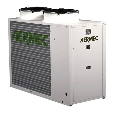
The NRP air/water OUTDOOR heat pump with gas
side conversion (R410A) is sent from the factory
already inspected and only requires electric and
hydraulic connections in the place of installation.
Before beginning the installation process, decide
with the client where the unit is to be installed,
whilst paying attention to the following:
1. The support surface must be capable of
supporting the unit weight.
2. The safety distances between the units
and other appliances or structures must be
scrupulously respected.
3. The unit must be installed by a qualified
technician in compliance with national laws in
the country of destination.
4. It is mandatory to foresee to the necessary
technical space in order to allow ROUTINE AND
EXTRAORDINARY MAINTENANCE interventions.
5. Remember that during operation, the
chiller can cause vibrations; therefore "VT"
anti-vibration mounts (ACCESSORIES) are
recommended, fixed on the base according to
the assembly layout.
6. Fix the unit checking that it is level.
1. RECEIPT OF THE PRODUCT AND INSTALLATION
ATTENTION
Lifting poles not supplied
EXAMPLE 1
"OF THE LIFTING"
Size NRP 0280-0700.
Insert pipes (NOT SUPPLIED) in holes on the base with
length such to allow positioning of the belts used for
lifting.
To prevent the unit structure being damaged by the belts
place protections between the latter and the machine.
It is prohibited to stop under the unit.
NOTE:
The appliance warranty does not cover the costs for lad-
ders, scaffolding, or other elevation systems that may
become necessary for carrying out servicing under
warranty.
EXAMPLE
2
"OF THE LIFTING"
NRP 0750 (always use all the provided eyebolts)
Before moving the unit, check the lifting
capacity of the machines used.
Once the packaging has been removed, the unit must
be handled by qualified personnel, using the appro-
priate equipment. To handle the machine:
"IN THE EVENT OF LIFTING", hook the lifting cables
to the special eyebolts In order to avoid damaging
the unit with the cables, insert protection elements
between them and the machine. Is it absolutely
forbidden to stand beneath
the unit.
5
