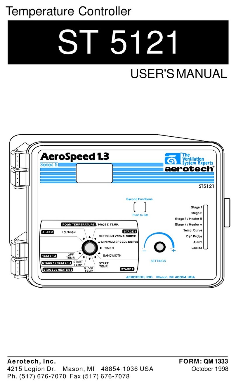
Aerotech ST 5110 User manual

ST 5110
Temperature Controller
USER'SMANUAL
Aerotech, Inc. FORM:QM1329
4215 Legion Dr. Mason, MI 48854-1036 USA October 1998
Ph. (517) 676-7070 Fax (517) 676-7078
ST5110

2QM1329.rev.00
TABLE OF CONTENTS
PRECAUTIONS.................................................................. 3
FEATURES ........................................................................ 4
LOCATION OF THE CONTROLS ...................................... 6
ControllerStatusLeds ...................................................... 7
InternalSwitches ............................................................... 7
INSTALLATION .................................................................. 8
MountingInstructions......................................................... 8
Connections ..................................................................... 8
MotorCurves .................................................................... 9
Heating/CoolingOption ................................................... 11
TemperatureProbes......................................................... 11
CHANGING THE PARAMETER SETTINGS...................... 13
TheMeaningofaFlashingDisplay ................................... 13
LockingtheParametersSettings ...................................... 13
TEMPERATURE SETTINGS ............................................. 14
TemperatureUnits ............................................................ 14
ViewingTemperatures...................................................... 14
TemperatureSetPoint...................................................... 17
TemperatureCurve ........................................................... 18
VENTILATION SETTINGS ................................................. 22
CoolingOperation............................................................. 22
MinimumVentilationCycle ................................................ 23
VentilationSettings ........................................................... 25
MinimumVentilationSpeedCurve .................................... 26
Mist Cooling ..................................................................... 32
HEATER SETTINGS .......................................................... 34
ALARM SETTINGS ............................................................ 36
TROUBLESHOOTING GUIDE ........................................... 37
TECHNICAL SPECIFICATIONS ........................................ 42
FACTORY SETTINGS ........................................................ 43
Page

3
QM1329.rev.00
We strongly recommend installing supplementary natural
ventilation, a failure alarm system as well as a back-up ther-
mostat on at least one cooling stage (refer to the wiring
diagram enclosed with this user's manual to connect the ther-
mostat).
Althoughfusesattheinputand outputs of the controller protect
its circuits in case of an overload or overvoltage, we
recommend installing an additional protection device on the
supply circuit as well as an external relay on all ON-OFF sta-
ges to prolong the life of the controller.
The room temperature where the controller is located MUST
ALWAYS REMAIN BETWEEN 32°F AND 104°F (0°C TO 40°C).
To avoid exposing the controller to harmful gases or exces-
sive humidity, it is preferable to install it in a corridor.
DO NOT SPRAY WATER ON THE CONTROLLER
PRECAUTIONS
FORCUSTOMERUSE
Enter below the serial number located
on the side of the controller and retain
this information for future reference.
Model number: ___ST 5110___
Serial number: _____________
Date installed: _____________

4QM1329.rev.00
The ST 5110 is an electronic device used for environmental control in live-
stock buildings. It allows the user to maintain a specified target tempera-
tureby controlling the operation of ventilation andheating equipment. One
stage of variable speed cooling fans can be connected to the controller, as
wellasone stageof eitherconstant-speedfans orheating units. Inaddition,
the last cooling stage can be configured as a mist cooling stage.
Themain features of the ST5110 are as follows:
THREE-DIGITDISPLAY
A three-digit display provides a high level of accuracy, allowing the user to
specifya temperature to within onetenth of a degree (inFahrenheit or Cel-
sius units).
PILOT LIGHTS
Pilot lights indicating the state of outputs allow the user to monitor the
operation of the system without having to enter the building.
MINIMUM VENTILATION CYCLE
Whenventilation isnot requiredfor cooling,the firststage fans canbe oper-
ated either continously or intermittently to reduce the level of humidity and
supply oxygen to the room.
TEMPERATUREAND MINIMUMVENTILATIONSPEED CURVES
Thecontroller can beset to automaticallychange the temperatureset point
andtheminimumventilation speedoveragivenperiod oftimeinaccordance
withthe user's requirements by specifyinga temperature curve and amini-
mum ventilation speed curve with up to six different points each.
CHOICE OF FIVE MOTOR CURVES
Thevariation in motorspeed resulting froma change involtage will depend
onthe make andcapacity ofthe motor. In order toachieve a high degree of
compatibilitybetweencontrollerand motor,theusercan choosefromamong
fivedifferentmotor curves,thusensuring thatthecorrectvoltage issupplied.
FEATURES

5
ST 5110
QM1329.rev.00
FULL-SPEEDFAN START-UP
In order to overcome the inertia of the ventilation system components and
de-ice the fan blades in cold weather conditions, the controller supplies
maximum voltage to the variable speed fans for 2 seconds immediately
followingeach start-up.
FOURINDEPENDENTTEMPERATUREPROBE INPUTS
Upto fourtemperature probescan beconnected tothe controllerin orderto
obtain a more accurate reading of the average room temperature and a
fasterreaction time.
OVERLOADAND OVERVOLTAGE PROTECTION
Fuses are installed at the input and outputs of the controller to protect its
circuitryin the caseof anoverload or overvoltage.
COMPUTERCONTROL
The controller can be connected to a computer, thus making it possible to
centralizethe management of information and diversify controlstrategies.
CONTROL OF AIR INLET MOVEMENT
If the ST 5110 is used in combination with a SB 2000 controller, the move-
mentof theair inletscan becoordinated withthe operationof thefans using
a potentiometer located on the curtain machine or baffle actuator. This
allowsthe airinlets to beadjusted correctly, withoutthe influenceof uncon-
trollable factors such as wind or air from adjoining rooms. When tunnel
ventilation is being used, the SB 2000 closes the air inlets.
HIGH/LOWTEMPERATUREALARM OUTPUT

6QM1329.rev.00
LOCATIONOFTHECONTROLS
AEROTECH, INC. Mason, MI 48854 USA
ST5110

7
ST 5110
QM1329.rev.00
DELGNINAEM
1EGATS .NOERASNAF1EGATSNEHWNOSNRUT
/2EGATS
ARETAEH .NOERASTINUGNITAEHROSNAF2EGATSNEHWNOSNRUT
.PMET
EVRUC
.DETAVITCASIEVRUCERUTAREPMETEHTNEHWSEHSALF SIEVRUCDEEPSNOITALITNEVMUMINIMEHTNEHWNOSNRUT
.NOOSLA
EBORP.FED .DETCETEDSIEBORPEVITCEFEDANEHWNOSNRUT
MRALA .DETCETEDSIMRALANANEHWNOSNRUT
DEKCOL .DEKCOLERASRETEMARAPRELLORTNOCNEHWNOSNRUT
CONTROLLER STATUS LEDS
#FFONO
1
DEKCOLNU
SRETEMARAP SRETEMARAPDEKCOL
2SEERGEDTIEHNERHAFSEERGEDSUISLEC
3GNILOOC2EGATSGNITAEH2EGATS
INTERNAL SWITCHES
The internal switches are located on the inside of the front cover. When
the controller is shipped from the factory, all the switches are set to OFF.
ON
2
134675 89 11
10 12

8QM1329.rev.00
Toconnectthecontroller,refertothewiringdiagramenclosedwiththisuser's
manual.
nSetthevoltageswitchtotheappropriatevoltage.
nUse the electrical knockouts provided at the bottom of the enclosure.
Do not make additional holes in the enclosure, particularly on the top
ofthe enclosure whenusing aSL 1400 communicationboard.
nIf metallic cable holders are used to secure cables entering the
enclosure,usethegroundplateprovidedwiththecontroller. Connect
the ground wire to the ground stud on the plate.
nFor the heating stages, it may be necessary to install a transformer in
orderto supplytheappropriate voltageto theheating unit.
ALARMCONNECTION: Therearetwotypesofalarmsonthemarket. One
typeactivateswhencurrentiscutoffatitsinput,whereastheotheractivates
whencurrentissuppliedatitsinput. Foranalarmofthefirsttype,usetheNO
terminalasshownonthewiringdiagram. Foranalarmofthesecondtype,use
theNCterminal.
Openthelatchandliftthecover.Removetheblackcapslocatedoneachof
thefourmountingholes. Mounttheenclosureonthewallusingfourscrews.
Besure theelectrical knockouts areat thebottom ofthe enclosure inorder
topreventwaterfromenteringthecontroller.Insertthescrewsinthemounting
holesandtighten. Fastenthefourblackcapsprovidedwiththecontrolleronto
thefour mounting holes. The enclosuremust be mounted in alocation that
will allow the cover to be completely opened right up against the wall.
ALLWIRINGMUSTBEDONEBYANAUTHORIZEDELECTRICIAN
AND MUST COMPLY WITH APPLICABLE CODES, LAWS AND
REGULATIONS.BESUREPOWERISOFFBEFOREDOINGANY
WIRINGTOAVOIDELECTRICALSHOCKSANDEQUIPMENTDAM-
AGE.
INSTALLATION
MOUNTING INSTRUCTIONS
CONNECTIONS
!
WARNING

9
ST 5110
QM1329.rev.00
Therelationship betweenthe voltagesupplied toa motorand itsoperating
speed is described by a motor curve. This curve varies with the make and
capacityofthemotor. Thevariousmotorsavailableintheindustryhavebeen
dividedintofivecategoriesandthecontrollerhasbeenprogrammedwitha
different motor curve for each of these categories. To ensure that the
controller supplies the correct voltages, an appropriate curve must be
selectedforStage1 accordingtothe typeoffanmotors used(seetableon
followingpage).
Selecting a Motor Type
Refer to the list of motors on the following page to determine which type
number (1 to 5) is appropriate for the motors used.
nSet the selection knob to
STAGE 1 — BANDWIDTH. The
Stage1bandwidthflashesonthe
display.
nPress the push-button. The cur-
rently selected type is displayed,
alternating with the letters "tYP".
nUsetheadjustmentknobtoadjustthemotortypetothedesiredvalue.
nReturn to the Stage1bandwidthdisplayby pressingthepush-button.
MOTOR TYPES

10
ST 5110
QM1329.rev.00
Fan
Dia.
9"
14"
15"
16"
18"
24"
36"
Model Numbers
AT09Z1, AT10SP1, AT10AP1 (120 VAC)
AT09Z2, AT10SP2, AT10AP2 (240 VAC)
AT14Z, AT14F, AT14G
AT15AP, AT15SP
AT16Z, AT16F, AT16G
AT18Z, AT18F,AT18G,GB18
AT24Z, AT24F,AT24G,GB24
AT36Z, AT36ZB1,AT36G1,AT36GB1
Motor
Curve
1
1
1
1
3
3
4
5
Minimum
Speed
45
45
65
65
30
40
40
30
Minimum
Voltage
Output
81
42
101
101
101
107
117
130
CFM
at 0.05"
S.P.
50
50
120
110
140
600
1250
1250
Minimum Speed Setting and Motor Curve Selection
Control Settings
Theabove values assumethe following conditions unless noted otherwise:
1) Input Voltage: 240 VAC
2) Static Pressure: 0.05" S.P.
3) Fan Accessories: Hood, Guard and Shutter if applicable.
For configurations or requirements other than above, refer to Form QM1065.

11
ST 5110
QM1329.rev.00
1
Connecting the Probes
Thecontrollerissuppliedwithoneroomprobeconnectedtoinput#1. Three
additionalprobescan beconnected toinputs# 2,3 and4in orderto obtain
a more accurate reading of the average room temperature and a faster
reactiontime(seewiringdiagramenclosed).
CAUTION: Probes operate at low voltage and are isolated from the
supply. Be sure that probe cables remain insulated from all high voltage
sources. In particular, do not route the probe cables through the same
electricalknockoutasothercables. Donotconnecttheshieldfromtheprobe
cable to an input or a ground.
2
Extending the Probes
Eachprobecanbeextendedupto500feet(150meters). Toextendaprobe:
nUseashieldedcableofoutsidediameterbetween0.245and0.260in
(6.22 and 6.60 mm) (the cable dimensions should not be under 18
AWG) to ensure the cable entry is liquid tight. Do not ground the
shielding.
TEMPERATURE PROBES
Stage 2 can operate as a heating or cooling stage.
ðSetswitch # 3 toOFF to use stage2 for
cooling.
ðSet switch # 3 to ON to use Stage 2 for
heating.
HEATING / COOLING OPTION
3
ON

12
ST 5110
QM1329.rev.00
nIt is preferable to solder the cable joint to ensure a proper contact
betweenthetwocables.
CAUTION: Donotrunprobecablesnexttootherpowercables. When
crossing over other cables, cross at 90°.
3
Defective Probes
Ifadefectiveprobeisdetected,theDefectiveProbePilotLightturnson.The
room temperature shown on the display is then the average temperature
measured by the probes in working condition. The controller will operate
accordingtothistemperature.
Toidentifythedefectiveprobe:
nSetthe selection knobto ROOM
TEMPERATURE.Theroomtem-
peratureis displayed.
nPress the push-button. If the
probeconnected to input# 1and
suppliedwith the controlleris not
defective,theletters"PR1"aredis-
played,alternatingwith theon/off
state of the probe and the tem-
peraturemeasured bythe probe.
If the probe is defective, the letters "PR1" are displayed, alternating
with the state of the probe and the letter "P".
Foreach additional probe connected tothe controller:
nPress the push-button once again. If the probe is not defective, the
letters "PR#" (where # is the number of the input to which the probe
is connected) are displayed, alternating with the on/off state of the
probe and the temperature measured by the probe. If the probe is
defective,the letters "PR#" are displayed,alternating with the on/off
state of the probe and the letter "P".

13
QM1329.rev.00
The parameter settings can be locked to prevent accidentally modifying
them. Whenthe settings arelocked, onlythe temperature setpoint and the
Stage 1 minimum ventilation speed can be modified (as long as the tem-
perature curve and the minimum ventilation speed curve are deactivated
respectively).
To lock the parameter settings:
nSet internalswitch #1 to ON. TheLocked ParameterPilot Light turns
on.
To unlock the parameter settings:
nSet internal switch # 1 to OFF. The Locked Parameter Pilot Light
turnsoff.
The display will flash in cer-
tain cases and not in others.
Theflashingindicatesthatthe
valueshowncan beadjusted.
A value that is not flashing
cannotbe adjusted.
CHANGING THE PARAMETER SETTINGS
THE MEANING OF A FLASHING DISPLAY
LOCKING THE PARAMETER SETTINGS
78.0

14 QM1329.rev.00
Temperatures can be displayed in either Celsius or
Fahrenheitunits
nSet internal switch # 2 to the desired position:
• ON to display temperatures in Celsius units.
• OFF to display temperatures in Fahrenheit units.
TEMPERATURESETTINGS
Thereadoutcandisplayvaluesfrom-
40.0oF to 120oF ( -40.0oC to 48.9oC).
When the temperature drops below -
9.9 degrees, the negative sign is dis-
playedseparately,alternatingwiththe
numericalvalue.
1
Viewing the Room Temperature
Theroomtemperatureistheaveragevalueofalltemperaturesmeasuredby
activatedprobesinproperoperatingcondition.
nSet the selection knob to ROOM TEMPERATURE / PROBE TEMP.
Theroom temperature isdisplayed.
2
Viewing the Probe Temperatures
Thecontrollercandisplayprobetemperaturesindividually. Probescanalso
beturnedonoroff tocontrolthetemperatureindifferentpartsofthebuilding.
nSetselection knob toROOM TEMPERATURE / PROBE TEMP. The
averageroom temperatureis displayed.
TEMPERATURE UNITS
VIEWING TEMPERATURES
ON
2

15
ST 5110
QM1329.rev.00
nPressthe push-button. The temperature reading fromprobe 1 is dis-
played,alternating with the letters "Pr 1"and theon/off state of probe
1.
nFor each additional probe, press the push-button. The temperature
reading from probe x is displayed, alternating with the letters "Pr x"
and the on/off state of the probe, etc.
nPress the push-button once again to display the letters "Pr 1" alter-
nating with the state of probe 1 , i.e. ON / OFF (flashing). When a
probe is activated, it is used in the calculation of the average room
temperature.
nUse the adjustment knob to change the state of the probe.
nFor each additional probe, press the push-button. The state of probe
is displayed, alternating with the letters "Pr x", etc.
Notes:
(i) Thedisplay returns to theaverage room temperature afterone minute.
(ii) Initially, only probe one is activated.
(iii) At least one probe must be activated at all times.
3
Viewing Minimum / Maximum Temperatures
Theminimum and maximumtemperatures are thelowest and highesttem-
perature values recorded since the last reset. Maximum and minimum
temperaturesvaluesare recordedforthe averageroomtemperatureas well
asforindividual probetemperatures.
nSet the selection knob to ROOM TEMPERATURE / PROBE TEMP.
Theroom temperature isdisplayed.

16
ST 5110
QM1329.rev.00
nTurn the adjustment knob clockwise by one notch. The minimum
temperature is displayed, alternating with the letters "Lo".
nTurn the adjustment knob clockwise one notch further. The maxi-
mum temperature is displayed, alternating with the letters "Hi".
nTurn the adjustment knob clockwise a third notch. The room tem-
peratureis displayed again.
nFor each individual probe, press the push-button. The temperature
reading from probe x is displayed, alternating with the letters "Pr x"
and the on/off state of the probe.
nTurn the adjustment knob clockwise by one notch. The minimum is
displayed, alternating with the letters "Lo".
nTurnthe adjustmentknob clockwiseone notchfurther. The maximum
temperature is displayed, alternating with the letters "Hi".
nTurn the adjustment knob clockwise a third notch. The probe tem-
peratureis displayed again.
nFor each additional probe, press the push-button. The temperature
reading from probe x is displayed, alternating with the letters "Pr x"
and the on/off state of the probe, etc.
NOTE: If you let the display flash for more than 10 seconds, the control-
ler resets the minimum and maximum temperatures currently in memory
(the display stops flashing to indicate that the reset has been done).

17
ST 5110
QM1329.rev.00
TEMPERATURE SET POINT
Thetemperature set pointis the target
room temperature. It can be adjusted
between -40.0°Fand 99.9°F (-40.0°C
and37.7°C).
Adjusting the Temperature Set Point
nSettheselectionknobtoSETPOINT/TEMP.CURVE.Thecurrentset
point flashes on the display.
nUse the adjustment knob to adjust the set point to the desired value.
NOTE: Thetemperaturesetpointcanbeadjustedonlyifthetemperature
curveisdeactivated(seefollowingsection).

18
ST 5110
QM1329.rev.00
Theusercandefineatemperaturecurvetoadjustthesetpointautomatically
overagiventimeperiod.
Acurveisdefinedusingsixpoints. Eachpointspecifiesadaynumberand
asetpointforthatday. Oncethepointsofthecurvearedefined,thecurve
mustbeactivated. Thecontrollerwillchangethetemperaturesetpointevery
hourinalinearfashionbetweenconsecutivepointsofthecurve. Whenthe
last point of the curve is reached, the temperature set point for that day is
maintaineduntilthecurveisreactivated.
NOTES :
i)Allsixpointsofthecurvemustbespecified. Ifsixpointsarenotneeded,
repeatthelasttemperaturevalueforeachunnecessarypoint.
ii) Certain restrictions apply to reduce the risk of errors:
−The highest possible day number is 99.
−Decreasingday numbers arenot allowed.
−Increasingtemperaturesarenotallowed.
−Thetemperaturevariationcannotexceed3°F(1.6°C)perday.
TEMPERATURE CURVE
Temperature
Days
To1
To2
To3
To4
To5
To6
d4 d25 d35 d50 d70 d80
○○ ○○○○○○○○
○○○○○○○○○
○○○○○○○○
○○○○○○
○○○○○
○○○○

19
ST 5110
QM1329.rev.00
1
Specifying the Curve
nSet the selection knob to SET
POINT / TEMP. CURVE. The
current temperature set point
flashes on the display.
nPressthepush-button. ThewordOFFisdisplayedindicatingthatthe
termperaturecurveisdeactivated. Ifthisisnotthecase,seebelowto
deactivatethecurve.
Repeat the following steps for each of the six points:
nPress the push-button once again. The word "day" is displayed,
alternatingwiththedaynumber.
nUsingtheadjustmentknob,setthedaynumbertothedesiredvalue.
nPressthepush-buttononceagain. Thecurrenttemperaturesetpoint
is displayed, alternating with the word "set".
nUsingthe adjustmentknob, adjust theset pointto thedesired value.
Oncethesixpoints ofthecurvehavebeen specified,activatethecurve as
explainedbelow.
NOTE: Makesure thetemperature curveis deactivatedbefore specifying
newpoints (see below).

20
ST 5110
QM1329.rev.00
2
Activating the Temperature Curve
If you have just finished specifying the points on the curve:
nPress the push-button once again. The word OFF flashes on the
display.
nTurntheadjustment knobclockwise onenotch. Theword ON flashes
onthe displayand theTemperatureCurve PilotLight flashes, indicat-
ingthat the temperature curveis now activated.
nSetthe selectionknob to ROOM TEMPERATURE.
Ifyou have previouslydefined thepoints on thecurve:
nSet the selection knob to SET POINT / TEMP. CURVE. The current
value of the temperature set point flashes on the display.
nPress the push-button. The word OFF flashes on the display.
nPress the push-button to display the points of the curve currently
defined until the word OFF appears(thirteen clicks).
nTurntheadjustment knobclockwise onenotch. Theword ON flashes
onthe displayand theTemperature CurvePilot Lightflashes, indicat-
ingthat the temperature curveis now activated.
nSetthe selectionknob to ROOM TEMPERATURE.
Table of contents
Other Aerotech Temperature Controllers manuals
Popular Temperature Controllers manuals by other brands

COQON
COQON qheat RS Installation & user guide

nvent
nvent Raychem RTD3CS installation instructions

Honeywell
Honeywell PRO 2000 Series Product data

Daikin McQuay
Daikin McQuay IOM 1177 Installation operation & maintenance data

Oregon Scientific
Oregon Scientific PSR01A user manual

LEGRAND
LEGRAND 5739 18 installation manual