Aerservice Equipments OTS User manual
OTS
SUNTO
User manual
Instructions for
use and
maintenance
©| Aerservice Equipments S.r.l.
2021 all rights reserved
Reproduction of this manual, total or partial, is forbidden

Instruction manual for use and maintenance - EN
Rev.: 0 –aggiornato al 06/11/2020
| Con riserva di modifiche tecniche e salvo errori |
Pag. 1di 39
Index
1. GENERAL INFORMATION........................................................................................................................... 3
1.1. Introduction....................................................................................................................................... 3
1.2. Information on copyright and related rights..................................................................................... 3
1.3. Instructions for the user.................................................................................................................... 3
2. SAFETY ....................................................................................................................................................... 4
2.1. General information.......................................................................................................................... 4
2.2. Warnings and symbols in the user manual ....................................................................................... 4
2.3. Signs applied by the user................................................................................................................... 4
2.4. Safety warnings for the operator ...................................................................................................... 5
2.5. Safety warnings for maintenance and troubleshooting.................................................................... 5
2.6. Warning about specific dangers........................................................................................................ 6
3. UNIT DESCRIPTION .................................................................................................................................... 7
3.1. Purpose.............................................................................................................................................. 7
3.2. Features and versions........................................................................................................................ 8
3.3. Proper use ......................................................................................................................................... 8
3.4. Improper use of the unit ................................................................................................................... 9
3.5. Marks and labels on the unit............................................................................................................. 9
3.6. Residual risk..................................................................................................................................... 10
4. TRANSPORT AND STORAGE..................................................................................................................... 10
4.1. Transport ......................................................................................................................................... 10
4.2. Storage............................................................................................................................................. 10
5. ASSEMBLY................................................................................................................................................ 11
5.1. Unpacking and castors assembling.................................................................................................. 11
5.2. Flexible hose assembly .................................................................................................................... 12
6. USE........................................................................................................................................................... 12
6.1. User qualification............................................................................................................................. 12
6.2. Control panel................................................................................................................................... 13
6.3. Correct use of the fume torch......................................................................................................... 14
6.4. Electric connection .......................................................................................................................... 15
6.5. Start of the unit ............................................................................................................................... 15
6.6. Automatic Start-Stop....................................................................................................................... 15
7. REGULAR MAINTENANCE ........................................................................................................................ 17
7.1. Care.................................................................................................................................................. 17
7.2. Ordinary maintenance..................................................................................................................... 18
7.3. Replacement of filters ..................................................................................................................... 18
7.4. Digital control panel: alarms and alarm reset................................................................................. 20

Instruction manual for use and maintenance - EN
Rev.: 0 –aggiornato al 06/11/2020
| Con riserva di modifiche tecniche e salvo errori |
Pag. 2di 39
7.5. Troubleshooting .............................................................................................................................. 22
7.6. Emergency measures....................................................................................................................... 22
8. DISPOSAL ................................................................................................................................................. 23
8.1. Plastics............................................................................................................................................. 23
8.2. Metals.............................................................................................................................................. 23
8.3. Filtering media................................................................................................................................. 23
9. ATTACHMENTS ........................................................................................................................................ 24
9.1. OTS 1torch Technical data.............................................................................................................. 24
9.2. OTS 1torch / inverter Technical data............................................................................................... 25
9.3. OTS 2torches Technical data .......................................................................................................... 26
9.4. OTS 2torches / inverter Technical data........................................................................................... 27
9.5. Spare parts and accessories ............................................................................................................ 28
9.6. EC declaration of conformity........................................................................................................... 29
9.7. UK Declaration of Conformity (UKCA)............................................................................................. 30
9.8. Dimensional drawing....................................................................................................................... 31
9.9. Wiring diagram OTS 1t..................................................................................................................... 32
9.10. Wiring diagram OTS 1t + inverter................................................................................................ 32
9.11. Wiring diagram OTS 2t –400V..................................................................................................... 33
9.12. Wiring diagram OTS 2t –110V..................................................................................................... 33
9.13. Wiring diagram OTS 2t + inverter –400V.................................................................................... 34
9.14. Schema elettrico OTS 2t + inverter –230V ................................................................................. 34
9.15. Inverter technical data ................................................................................................................ 35
9.16. Air connection ............................................................................................................................. 37

Instruction manual for use and maintenance - EN
Rev.: 0 –aggiornato al 06/11/2020
| Con riserva di modifiche tecniche e salvo errori |
Pag. 3di 39
1. GENERAL INFORMATION
1.1. Introduction
This user manual provides important information for the correct and safe operation of Aerservice
Equipments’ mobile filter unit OTS suitable for extraction of welding fumes.
The instructions contained in this manual help to avoid dangers, to reduce repair costs and machine
downtime and to increase the reliability and lifetime of the unit.
The user manual shall always be at hand; all information and warnings contained therein shall be read,
observed and followed by all people who work by the unit and are involved in tasks, such as:
-transport and assembly;
-normal use of the unit during work;
-maintenance (replacement of filters, troubleshooting);
-disposal of the unit and its components.
1.2. Information on copyright and related rights
All information included in this instruction manual must be treated confidentially and may be made
available and accessible only to authorized people.
It may be disclosed to third parties only with the prior written consent of Aerservice Equipments.
All documentation is protected under the copyright law.
Any distribution or reproduction, in total or partial, of this document, as well as its use or transmission
without prior and explicit authorization by Aerservice Equipments, is prohibited.
Any violation of this prohibition is punishable by law and involves penalties.
All rights relating to industrial property rights are reserved to Aerservice Equipments.
1.3. Instructions for the user
These Instructions are an integral part of the unit OTS.
The user must ensure that all personnel in charge of the unit have adequate knowledge of these
Instructions.
The user is required to complete the Manual with instructions based on national regulations for injury
prevention and environmental protection, including information on surveillance and notification
obligations, in order to consider specific requirements, such as organization of work, working methods
and personnel involved.
In addition to the instructions and regulations for the prevention of accidents, in force in the country
and in the place where the unit is used, it is necessary to comply with the common technical principles
for a safe and correct use of the unit.
The user shall not make any modifications to the unit, nor add parts or adjust it without permission by
Aerservice Equipments because this could jeopardize its safety!
The spare parts used shall correspond to the technical specs established by Aerservice Equipments.
Always use original spare parts to ensure correspondence of the unit to the technical specifications.
Allow only trained and expert personnel for the operation, maintenance, repair and transport of the
unit.
Establish individual responsibilities for operation, configuration, maintenance and repair.
Instruction manual for use and maintenance - EN
Rev.: 0 –aggiornato al 06/11/2020
| Con riserva di modifiche tecniche e salvo errori |
Pag. 4di 39
2. SAFETY
2.1. General information
The unit was developed and manufactured using the latest technology and in accordance with the
general workplace safety guidelines.
However, the use of the unit could present risks for the operator or risks of damage to the unit and other
objects:
-If the personnel in charge has not received instructions or training;
-In case of use that is not in accordance with the intended purpose;
-In case of maintenance that is not carried out as indicated in this manual.
2.2. Warnings and symbols in the user manual
This warning indicates an imminent dangerous situation.
Not respecting it can result in death or serious injury.
This warning indicates a possible dangerous situation.
Not respecting it can result in death or serious injury.
This warning indicates a possible dangerous situation.
Not respecting it can result in minor injury or material damage.
This warning provides useful information for safe and proper use.
•The point in bold marks the work and / or operating procedure.
The procedures need be performed in sequence.
-Any list is marked with a horizontal dash.
2.3. Signs applied by the user
The user is responsible for the application of signs on the unit or in the near area.
Such signs may concern, for example, the obligation to wear personal protective equipment (PPE).
Refer to the local regulations for advice.
DANGER
WARNING
WARNING
INFO

Instruction manual for use and maintenance - EN
Rev.: 0 –aggiornato al 06/11/2020
| Con riserva di modifiche tecniche e salvo errori |
Pag. 5di 39
2.4. Safety warnings for the operator
Before using the unit, the operator in charge must be suitably informed and trained for the use of the
unit and the relevant materials and means.
The unit must only be used in perfect technical condition and in compliance with the intended purposes,
the safety standards and the warnings relating to dangers as reported in this Manual.
All failures, especially those that can jeopardize safety, shall be removed immediately!
Each person responsible for commissioning, use or maintenance of the unit must be familiar with these
instructions and must have understood their content, especially paragraph 2 Safety.
It is not enough to read the manual for the first time when you are already working.
This is especially true for people who work on the unit only occasionally.
The manual shall always be available near the unit.
No liability is accepted for damage or injury due to failure to comply with these instructions.
Observe the current workplace precaution rules, as well as other general and standard technical safety
and hygiene tips.
Individual responsibilities for the various maintenance and repair operations must be clearly established
and respected. Only in this way malfunctions can be avoided - especially in dangerous situations.
The user shall ensure that the personnel responsible for use and maintenance of the unit shall wear
personal protective equipment (PPE). These are mainly safety shoes, goggles and protective gloves.
Operators must not wear long loose hair, baggy clothing or jewelry! There is a risk of being trapped or
drawn in by the moving parts of the unit!
In case of any changes on the unit, that may affect safety, switch off the equipment immediately, secure
it and report the incident to the department / person in charge!
Interventions on the unit can only be carried out by competent, reliable and trained personnel.
Personnel undergoing training or in a training program may only be permitted to work on the unit under
the constant supervision of a trained person.
2.5. Safety warnings for maintenance and troubleshooting
For all maintenance and troubleshooting, ensure to use suitable personal protective equipment.
Before proceeding with any maintenance work, clean the unit.
An industrial vacuum cleaner with H efficiency class for dust can be helpful.
The preparation, maintenance and repair operations, as well as the detection of faults can only be
carried out if the unit is without power supply:
•Remove the plug from the mains supply.
All screws that were loosened during maintenance and repair work need always be fastened again!
If so foreseen, the screws must be tightened with a torque wrench.
Before proceeding with maintenance and repairs it is necessary to remove all impurities, especially on
the parts fastened with screws.
Instruction manual for use and maintenance - EN
Rev.: 0 –aggiornato al 06/11/2020
| Con riserva di modifiche tecniche e salvo errori |
Pag. 6di 39
2.6. Warning about specific dangers
All work on the electrical device of the unit shall be carried out exclusively by a qualified
electrician or by personnel with the necessary training, under the direction and supervision
of a qualified electrician and in accordance with the relevant safety standards.
Before any activity on the unit, it is necessary to disconnect the electric plug from the mains
supply, to prevent accidental restarting.
Use only original fuses with the prescribed current limit.
All electrical components to be inspected, maintained and repaired must be disconnected.
Block the devices used to disconnect the voltage, in order to avoid accidental or automatic
restart.
First check the absence of voltage on the electric components, then isolate the adjacent
components. During repairs, be careful not to modify the factory parameters so as not to
jeopardize safety.
Check the cables regularly and replace in case of damage.
Skin contact with welding powders etc. can cause irritation to sensitive people.
Repair and maintenance of the unit must only be carried out by qualified and authorized
personnel, in compliance with safety requirements and accident prevention regulations in
force.
Danger of serious damages to respiratory system.
To prevent contact with dust and inhalation, use protective clothing and gloves and an
assisted ventilation device to protect the respiratory tissue.
During repairs and maintenance interventions, avoid diffusion of dangerous dust, in order
to prevent health damage even of people not directly affected.
The unit can produce noise emissions, specified in detail in the technical data.
If used with other machinery or due to the characteristics of the place of use, the unit may
generate a higher sound level.
In this case, the person in charge is required to provide the operators with adequate
protective equipment.
DANGER
WARNING
WARNING

Instruction manual for use and maintenance - EN
Rev.: 0 –aggiornato al 06/11/2020
| Con riserva di modifiche tecniche e salvo errori |
Pag. 7di 39
3. UNIT DESCRIPTION
3.1. Purpose
The unit is a compact mobile device suitable for filtration of welding fumes extracted directly at source,
with a high separation rate according to the specific application.
The unit can be equipped with one or two flexible hoses to fume torches (the flexible hose, the fume
torch and the quick coupling are not included in the unit).
The fumes (rich in polluting particulate) are purified through a multi-stage filtering section, before being
released back in the workplace.
Pos.
Description
Pos.
Description
1
Control panel
8
Filter inspection door lock
2
Air flow regulator
9
Flexible hose connection
3
On-Off switch
10
Swivel wheels with brake
4
Panel socket
11
Rear wheels
5
Inverter access door
12
Compressed air inlet
6
Mass cable clamp
13
Handles
7
Clean air expulsion grid
6
1
8
7
3
10
11
4
12
9
4
2
5
Instruction manual for use and maintenance - EN
Rev.: 0 –aggiornato al 06/11/2020
| Con riserva di modifiche tecniche e salvo errori |
Pag. 8di 39
3.2. Features and versions
The mobile air cleaner is available in five versions:
-OTS 1t
with cartridge filter - mechanical filtration
higher filter efficiency: ≥99% | M (sec. DIN 660335-2-69)
-OTS 1t / inverter
with cartridge filter - mechanical filtration
higher filter efficiency: ≥99% | M (sec. DIN 660335-2-69)
air flow regulation by inverter
-OTS 2t
with cartridge filter - mechanical filtration
higher filter efficiency: ≥99% | M (sec. DIN 660335-2-69)
-OTS 2t / inverter
with cartridge filter - mechanical filtration
higher filter efficiency: ≥99% | M (sec. DIN 660335-2-69)
air flow regulation by inverter
-OTS 2t / triac (only 110V)
with cartridge filter - mechanical filtration
higher filter efficiency: ≥99% | M (sec. DIN 660335-2-69)
air flow regulation by triac
3.3. Proper use
The unit has been conceived to extract and filter the welding fumes generated by industrial welding
processes, directly at source. In principle, the unit can be used in all work processes with emission of
welding fumes. However, it is necessary to prevent the unit from sucking in "spark showers" from
grinding or similar.
Pay attention to the dimensions and further data that are mentioned in the technical data sheet.
Carefully read and comply with the instructions in chapter “9.1 Technical data of the unit”.
The use in accordance with the instructions of this manual also means following the specific
instructions:
-for safety;
-for use and setting;
-for maintenance and repair,
mentioned in this user manual.
Any further or different use is to be considered as non-compliant.
The user of the unit is the sole responsible for any damage resulting from such non-
compliant use.
This also applies to arbitrary interventions and unauthorized modifications on the unit.
INFO

Instruction manual for use and maintenance - EN
Rev.: 0 –aggiornato al 06/11/2020
| Con riserva di modifiche tecniche e salvo errori |
Pag. 9di 39
3.4. Improper use of the unit
The unit is not suitable for use in hazardous areas falling under ATEX regulation.
Furthermore, the equipment should not be used in the following cases:
-Applications not corresponding to the intended purpose or not indicated for proper use of the unit
and in which the air to be extracted:
•contains sparks, for example from grinding, of a size and quantity such as to damage the suction
arm and set fire to the filtering section;
•contains liquids that may contaminate the air flow with vapors, aerosols and oils;
•contains easily flammable dusts and / or substances that may cause explosive mixtures or
atmospheres;
•contains other aggressive or abrasive powders that may damage the unit and its filters;
•contains organic and toxic substances / components (VOCs) which are released during the
separation process. Only by inserting the active carbons filter (optional) the unit becomes
suitable for filtration of these substances.
-The unit is in an outdoor area, where it is exposed to atmospheric agents: the unit must be installed
exclusively in closed and / or repaired buildings. Only a special version of the unit (with specific
indications for outdoors) can be installed outside.
Any waste, such as for example collected particles, may contain harmful substances, therefore they must
not be delivered to landfills for municipal waste. It is necessary to provide for an ecological disposal
according to local regulations.
If the unit is used in accordance with its intended purpose, there is no reasonably foreseeable risk of
improper use that might endanger health and safety of personnel.
3.5. Marks and labels on the unit
The unit has marks and labels which, if damaged or removed, need be immediately replaced with new
ones in the same position.
The user may have the obligation to place other marks and labels on the unit and in the surrounding
area, e.g. referring to the local regulations for the use of personal protective equipment (PPE).
Instruction manual for use and maintenance - EN
Rev.: 0 –aggiornato al 06/11/2020
| Con riserva di modifiche tecniche e salvo errori |
Pag. 10 di 39
3.6. Residual risk
The use of the unit involves a residual risk as illustrated below, in spite of all safety measures.
All users of the unit must be aware of the residual risk and follow the instructions to avoid any injury or
damage.
Risk of serious damage to the respiratory system - wear a protective device in class FFP2
or higher.
Skin contact with cutting fumes etc. can cause skin irritation in sensitive individuals.
Wear protective clothing.
Before carrying out any welding job, make sure that the unit is positioned / installed
correctly, that the filters are complete and intact and that the unit is active!
The unit can perform all its functions only when it has been switched on.
By replacing the various filters that make up the filtering section, the skin can come into
contact with the separated powder and the processes carried out can volatilize this
powder.
It is necessary and mandatory to wear a mask and a protective suit.
Burning material sucked in and trapped in one of the filters, can cause smoldering.
Switch off the unit, close the manual damper in the capture hood, and allow the unit
to cool down in a controlled manner.
4. TRANSPORT AND STORAGE
4.1. Transport
Danger of death from crushing during unloading and transport.
Improper maneuvers during lifting and transport can cause the pallet with the unit to
overturn and fall.
•Never stand under suspended loads.
A transpallet or forklift truck are suitable for transporting any pallet with the unit.
The weight of the unit is indicated on the rating plate.
4.2. Storage
The unit shall be stored in its original packaging at an ambient temperature between -20° C and
+50° C in a dry and clean place.
The packaging must not be damaged by other objects.
For all units, the duration of storage is irrelevant.
WARNING
DANGER
Instruction manual for use and maintenance - EN
Rev.: 0 –aggiornato al 06/11/2020
| Con riserva di modifiche tecniche e salvo errori |
Pag. 11 di 39
5. ASSEMBLY
Risk of serious injury when assembling the suction arm due to gas spring preload. A
safety lock is provided on the metal articulating arm assembly.
Improper handling can lead to risk of abrupt displacement of the metal articulating arm
assembly, resulting in severe injuries in the face or crushing of the fingers!
The user is required to appoint a specially trained technician to install the unit.
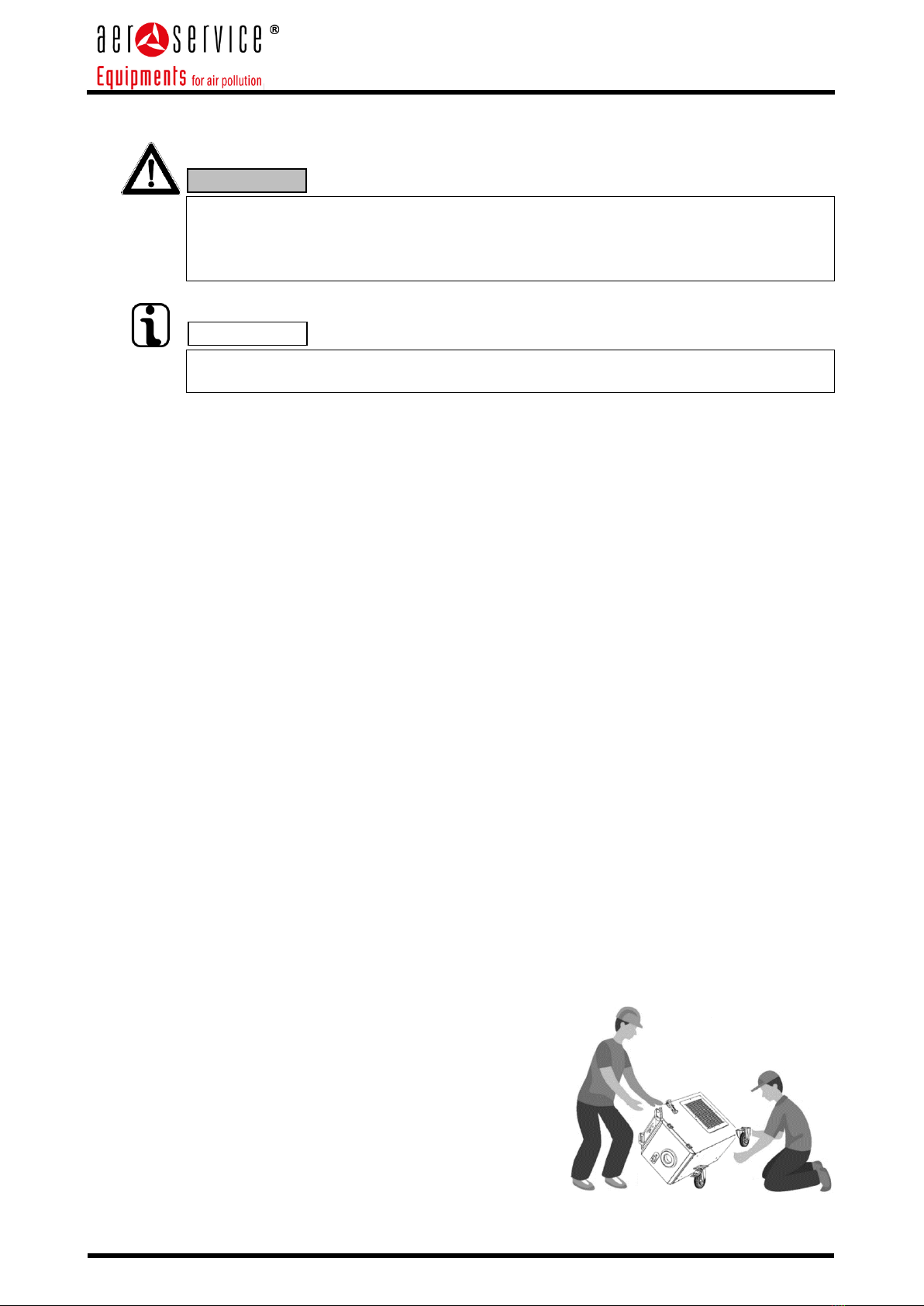
The assembling operations require the intervention of two persons.
5.1. Unpacking and castors assembling
The unit is delivered on a wooden pallet and protected by a cardboard box.
Pallet and box are held together by two straps.
A copy of the rating plate of the unit is applied also outside the box.
Prepare unpackaging as follows:
•Cut the straps with scissors or cutter;
•Lift up the cardboard box;
•Remove any additional packages contained inside and place them on the ground in a stable
manner;
•Using scissors or cutter, cut the strap blocking the unit on the pallet;
•Remove any packaging materials such as bubble nylon;
•If castors are already built in the unit, continue with this procedure otherwise go to note A;
•Block the front swivel castors by the brake;
•Let the unit slide off the pallet so that the two braked castors can rest on the floor;
•Extract the pallet from beneath the unit and place it carefully on the ground.
Note A:
In case of supply of the unit with castors to build in, it is necessary to proceed as per following
instructions:
•Shift the unit about 30cm off the pallet, from the front side;
•Place the castors with brakes under the unit;
•Assemble them in the unit using the screws that are provided in the package;
•Shift the unit about 30 cm off the pallet, from one side;
•Position and assemble one rear castor;
•Extract the pallet from beneath the unit and assemble the second rear castor.
WARNING
INFO
Instruction manual for use and maintenance - EN
Rev.: 0 –aggiornato al 06/11/2020
| Con riserva di modifiche tecniche e salvo errori |
Pag. 12 di 39
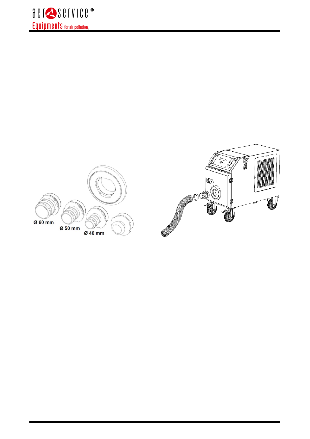
5.2. Flexible hose assembly
Depending on the version, the unit is equipped with 1 or 2 inlets on the front panel for extraction of
the welding fumes. The inlets shall never be removed from the front panel. A rapid connection or
change of the flexible hose is allowed by the quick coupling available from Aerservice Equipments.
If not specified or requested in advance, the coupling for Ø40mm hose is standard provided;
eventually it is possible to choose also the Ø50mm or Ø60mm coupling.
In the version with 2 inlets, 1 closing cap is also provided if it is necessary to close one of the two
inlets.
To carry out the correct assembly follow the procedure:
• Identify the correct quick coupling according to the flexible hose;
• Insert the hose on the coupling and secure with the hose clamp supplied;
• Insert the quick coupling on the ring nut of the unit;
• Lock by turning clockwise.
6. USE
Anyone involved in the use, maintenance and repair of the unit must have read and understood this user
manual as well as the instructions for accessories and related devices.
6.1. User qualification
The user of the unit can only authorize the use of the unit by personnel with a good knowledge of these
operations.
Knowing the unit means that the operators have been trained on the functions, and know the user
manual and operating instructions.
The unit shall only be used by qualified or duly trained personnel. Only in this way is it possible to
ensure working in a safe manner and in awareness of dangers.

Instruction manual for use and maintenance - EN
Rev.: 0 –aggiornato al 06/11/2020
| Con riserva di modifiche tecniche e salvo errori |
Pag. 13 di 39
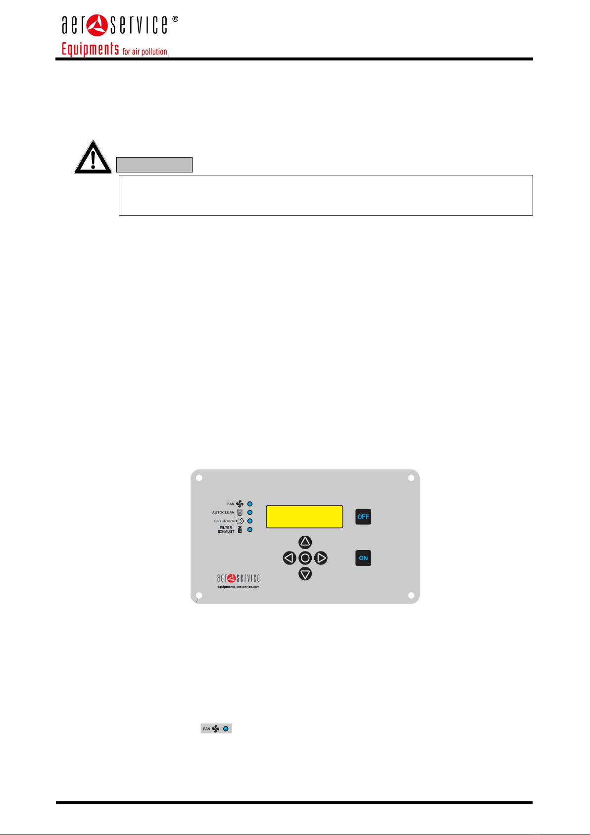
6.2. Control panel
On the front of the unit there is the control panel which is made up of electronic and pneumatic
devices.
Pos.
Description
Pos.
Description
1
LED Blower is running
6
ON blower starts
2
LED Filter-cleaning cycle is running
7
OFF blower stops
3
LED Filter clogged
8
Display
4
LED Replace filter
9
Air flow regulator
5
Control panel keys
Below the detailed description:
•[Position 1.]
After pressing the button ON (pos.6) the signaling LED lights up with a steady green light and
indicates that the electric motor has been powered and is running.
•[Position 2.]
LED indicator with alternating green light, indicates the start of the cartridge cleaning cycle
using compressed air.
•[Position 3.]
LED indicator with fixed yellow light, turns on after 600 hours of operation to advise to
perform a check on the filters (if not replaced yet) and a general check on the unit to verify
correct functioning.
•[Position 4.]
LED indicator with steady red light, lights up when the filter pressure differential gauge
detects a limit pressure difference (data set by the manufacturer) between the dirty air inlet
and the clean air outlet in the filtering section.
•[Position 5.]
Specific buttons on the control panel to move through the menus and / or modify the
parameters.
•[Position 6.]
ON key to start extraction - hold for 3s.
•[Position 7.]
OFF key to switch off extraction - hold for 3s.
•[Position 8.]
Display showing all information about the pcb.
•[Position 9.]
Air flow regulator (if provided) to increase or lower the extraction capacity of the unit.
1
2
3
4
5
6
8
7
9
Instruction manual for use and maintenance - EN
Rev.: 0 –aggiornato al 06/11/2020
| Con riserva di modifiche tecniche e salvo errori |
Pag. 14 di 39
6.3. Correct use of the fume torch
If the fume torch is not used correctly or in case of poor extraction, there is no guaranty for
purification of fumes containing dangerous vapors and micro-particles. Dangerous
substances can be inhaled by the operator and cause damage to health!
The welding torch with integrated fume extraction is not an integral part of the OTS unit,
therefore the user is required to be specifically informed and trained on the correct
operation and use of the welding torch.
In case of lack of specific information on the fume torch in use, the user of the OTS unit can
consider the guidelines provided below.
However, it is obligatory to gather that information in order to use the equipment correctly.
General guidelines for the use of the welding torch with integrated fume extraction:
• During welding, place the torch nozzle as vertical as possible in order to capture the fumes more
effectively;
• Place the torch nozzle close to the welding point to obtain better extraction of fumes and better
protection of the weld pool.
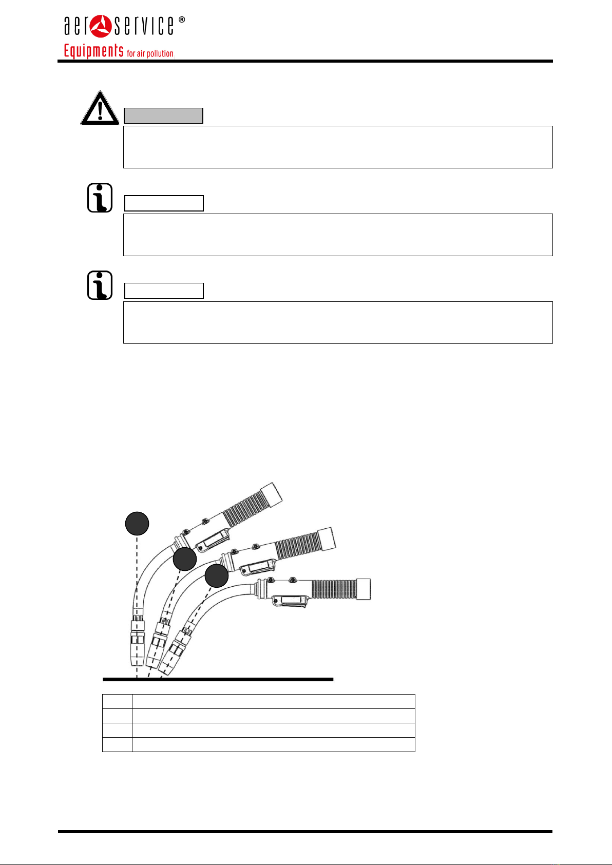
• The torch nozzle must be kept constantly with an inclination about >15°<45° with respect to the weld
pool to perform the best extraction together with a better welding quality.
• The maximum distance between the gas nozzle and the weld pool must always be kept below 1 cm,
especially for corner welding.
Pos.
Description
1
Position for the best extraction performance
2
Position with medium quality extraction
3
Position with a poor extraction performance
WARNING
INFO
INFO
1
2
3
Instruction manual for use and maintenance - EN
Rev.: 0 –aggiornato al 06/11/2020
| Con riserva di modifiche tecniche e salvo errori |
Pag. 15 di 39
6.4. Electric connection
Before switching on the OTS unit it is necessary to check the correct electric connection of the filtering
unit and ensure an adequate protection.
A thermal protection device is necessary to protect the fan motor from any current peak and short
circuit.
It is necessary to install a differential switch suitable for inverters.
OTS unit is equipped with an inverter complete with EMC filter which could interfere with
unsuitable differential switches!
6.5. Start of the unit
To start the unit proceed as follows:
•Connect the unit to the mains supply, making sure to carefully respect the data on the rating
plate;
•Connect the unit to the compressed air line making sure it is clean, dry and free from oil. The
incoming air pressure shall be 6 Bar steadily;
•Turn the yellow-red main switch to power the unit;
•Wait for the digital panel turning on;
•Press the ON key on the pc board for 3 secs;
•The extractor fan starts running and consequently the unit is opearating.
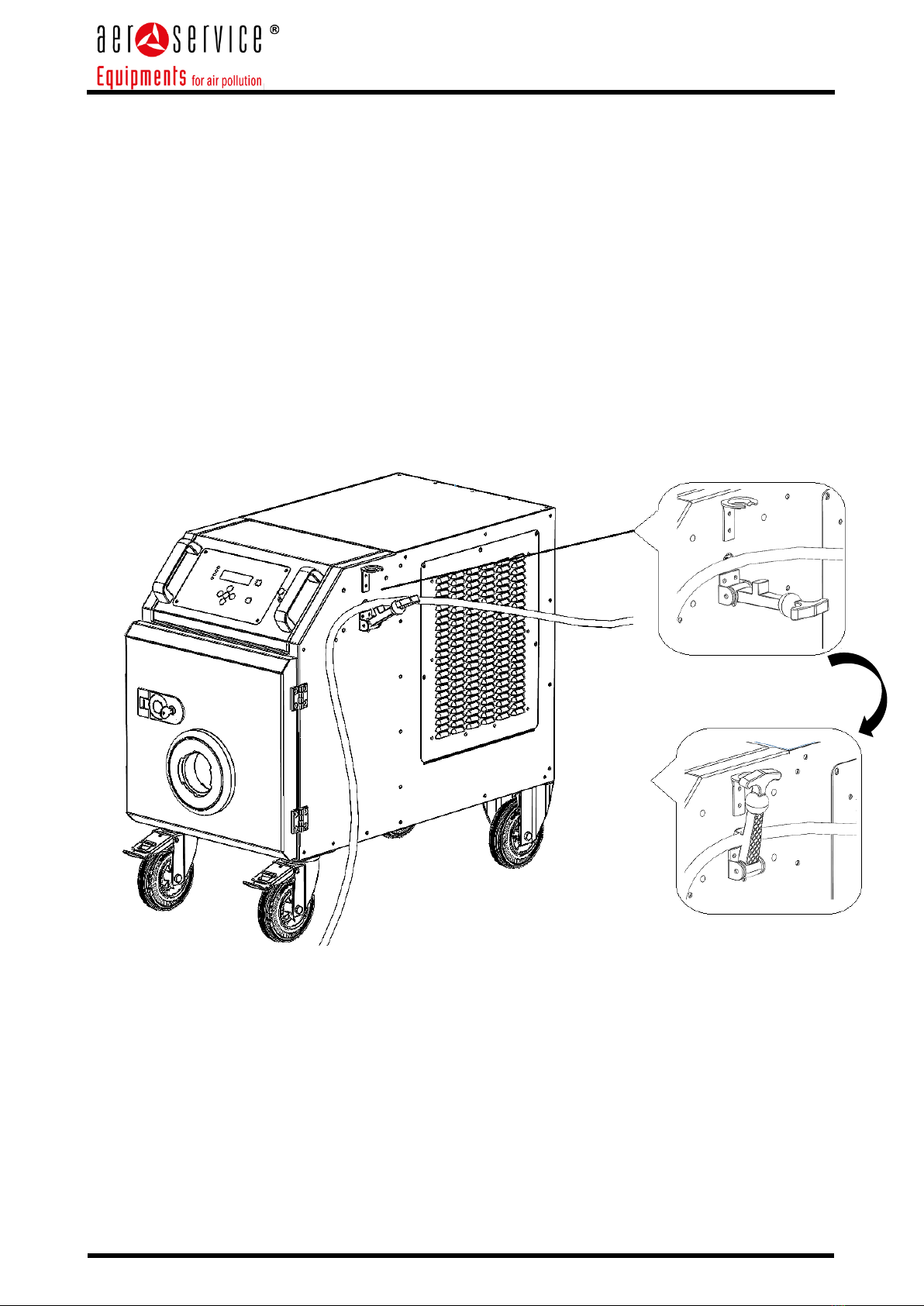
6.6. Automatic Start-Stop
The unit is standard provided with an automatic START-STOP electronic device which automatically
starts and stops the extraction according to the actual operation of the welding unit.
[picture 1: layout of the control panel]
The unit with automatic start and stop function has a special clamp on the side of the unit and also
specific indications in the display.
After having turned on the main switch of the unit, the pcb will turn on giving the following information:
•Software version installed
•Name and p/n of the unit
•Then the following information will be shown in the display: START-STOP ACTIVATED.
•The extraction LED will be flashing.
In this mode the unit is ready to work and it is sufficient to start welding to activate the fume extraction.
The unit is already sed to stop extracting after 1 minute from the last welding cycle.
WARNING
Instruction manual for use and maintenance - EN
Rev.: 0 –aggiornato al 06/11/2020
| Con riserva di modifiche tecniche e salvo errori |
Pag. 16 di 39
MANUAL OPERATION
It is possible to start the unit manually by pressing the ON button for a few seconds.
The message: MANUAL START ACTIVE will appear.
The operation of the filter unit will be active until the OFF button is pressed.
After turning off the extraction, the unit will automatically return to the automatic Start / Stop mode.
To ensure proper operation of the automatic Start / Stop device, it is essential that the ground cable of
the welding unit is placed on the metal cabinet of the filter unit and locked in position by the special
clamp.
Check that the ground cable is well in contact with the metal cabinet of the unit, as shown in the figure.
Instruction manual for use and maintenance - EN
Rev.: 0 –aggiornato al 06/11/2020
| Con riserva di modifiche tecniche e salvo errori |
Pag. 17 di 39
7. REGULAR MAINTENANCE
The instructions in this chapter correspond to the minimum requirements.
Depending on particular operating conditions, other specific instructions may be applicable to keep the unit
in a perfect conditions.
The maintenance and repairs described in this chapter may only be performed by qualified personnel.
The spare parts used must correspond to the technical requirements established by Aerservice Equipments.
This is always guaranteed if original spare parts are used.
Dispose in a safe and environmentally friendly way of the materials used and the components replaced.
Respect the following instructions during maintenance:
•Chapter 2.4 Safety warnings for the operator;
•Chapter 2.5 Safety warnings for maintenance and troubleshooting;
•Specific safety warnings, reported in this chapter in correspondence with each intervention.
7.1. Care
Taking care of the unit essentially means cleaning the surfaces, removing dust and deposits, and checking
the condition of the cartridge filter.
Follow the warnings indicated in the "Safety instructions for repairing and troubleshooting" chapter.
Skin contact with dust and other substances deposited on the unit can cause irritation to
sensitive persons!
Danger of serious damage to the respiratory system!
To avoid contact and inhalation of dust, it is recommended to use protective clothing, gloves
and a mask with a FFP2 class filter according to EN 149 standard.
During cleaning, prevent dangerous dust from being diffused in order to avoid damage to
the health of persons nearby.
The unit must not be cleaned with compressed air!
Particles of dust and / or dirt could be diffused in the surrounding environment.
Adequate consideration helps to keep the unit in perfect order for a long time.
•The unit shall be cleaned thoroughly every month.
•The external surfaces of the unit shall be cleaned with a “H” class industrial vacuum cleaner
suitable for dust, or with a damp cloth.
•Check that the extraction hose is not damaged, and that there are no breaks / cracks in the
flexible hose.
•Check that the whole torch assembly is in order to ensure best performance.
WARNING
INFO

Instruction manual for use and maintenance - EN
Rev.: 0 –aggiornato al 06/11/2020
| Con riserva di modifiche tecniche e salvo errori |
Pag. 18 di 39
7.2. Ordinary maintenance
To ensure a safe operation of the unit, it is advisable to carry out a maintenance activity and overall
check at least once every 3 months.
The unit does not require any specific maintenance, except for the replacement of the filters if necessary
and the inspection of the extraction hose and torch cable.
Follow the warnings given in paragraph 2.5 "Safety warnings for maintenance and troubleshooting".
7.3. Replacement of filters
The lifetime of the filters depends on the kind and quantity of particles extracted.
To optimize the life of the main filter and to protect it from coarser particles, the unit is provided with a
spark arrestor trap.
A differential filter pressure gauge checks the cartridge filter continuously which is cleaned automatically
by a counter current air shot.
The active carbon postfilter captures VOC volatile substances and provides for deodorization.
It is advisable to replace the cartridge filter, when it exhausted. The more is clogged the cartridge the
narrower is the air flow, with a reduction of the extraction capacity.
The unit is equipped in all versions with an audible and visual alarm that indicates the need
to carry out maintenance of the filters.
It is forbidden to clean fabric filters (all kinds): corrugated, pocket and cartridge filters.
Cleaning would cause damage to the filter stuff, compromising the function of the filter and
leading to escape of hazardous substances into the ambient air.
In case of a cartridge filter, pay particular attention to the filter seal; only if the seal is free
from damages or imperfections it is possible to guarantee a high level of filtration.
Filters with damaged seals shall always be replaced.
Skin contact with dust and other substances lying on the unit can cause irritation to sensitive
persons!
Danger of serious damage to the respiratory system!
To avoid contact and inhalation of dust, it is recommended to use protective clothing, gloves
and a mask with a FFP2 class filter according to EN 149 standard.
During cleaning, prevent dangerous dust from being diffused in order to avoid damage to
the health of other persons.
To this purpose, carefully insert the dirty filters inside bags with sealing and use an industrial
vacuum cleaner for dust with efficiency class "H" to suck up any dust dropped during the
filter extraction phase.
INFO
WARNING
WARNING
Instruction manual for use and maintenance - EN
Rev.: 0 –aggiornato al 06/11/2020
| Con riserva di modifiche tecniche e salvo errori |
Pag. 19 di 39
-Use only original replacement filters, as only these filters can guarantee the required filtration
level and are suitable for the unit and its performance.
-Turn off the unit by the yellow-red main switch.
-Secure the unit by pulling out the plug from the mains, so that it cannot be accidentally
restarted.
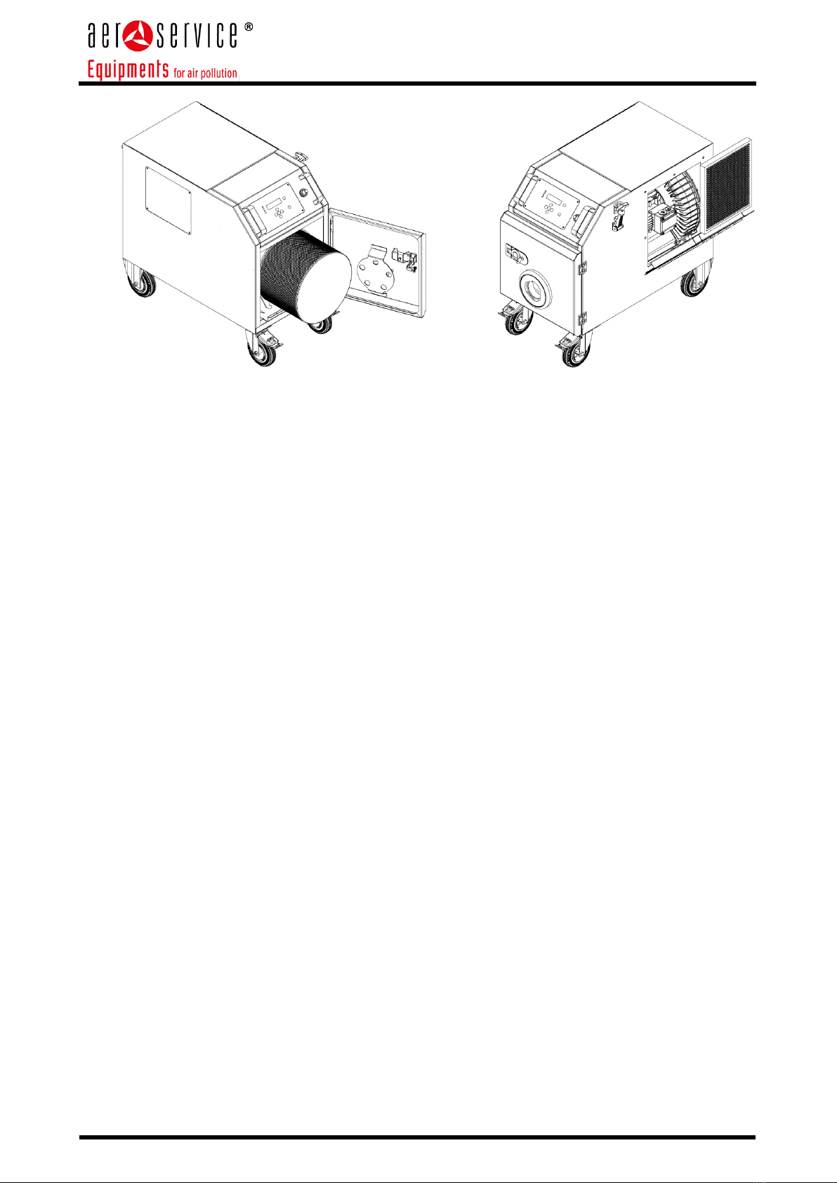
-Open the inspection door on the side of the unit.
a) Replacing the cartridge filter
-Carefully take out the cartridge filter, taking care to avoid any lifting up of dust.
-To extract it, it is necessary to loosen the 3 screws on the flange.
-Carefully place the filter in a plastic bag and close it, for example with cable ties.
-Suitable plastic bags can be supplied by Aerservice Equipments.
-Insert the new cartridge filter in the special support inside the unit and fasten with the screws.
b) Replacing the active carbons filter:
-Open the air grid on the side of the cabinet.
-Carefully take out the filter avoiding any dust diffusion and close it in a sealed plastic bag.
-Insert the new filter in the guides behind the grid and fasten again with the screws.
c) Once the filters have been replaced, proceed as per the following steps:
-Close the inspection door and check that it is completely closed and that the sealing gasket is
positioned correctly.
-Reinsert the plug into the mains socket and turn on the yellow-red main switch.
-Reset alarms as indicated under point 7.4.
-Dispose of the dirty filters according to the regulations in force locally. Ask the local waste
disposal company for the relevant waste disposal codes.
-Finally clean the surrounding area, e.g. with an "H" class industrial vacuum cleaner for dust.
Table of contents
Other Aerservice Equipments Welding Accessories manuals


