AES IntelliNet 7067 IntelliTap-II User manual

Page 1 of 4AES•IntelliNet Model7067IntelliTap-II
AES Corporation Doc# 40-7067, 6/9/09
AES 7067 IntelliTap-II Digital Dialer Interface
A Supplemental Alarm Reporting Device
WARNING: Test this system periodically for proper operation. AES
assumes no responsibility for this equipment's failure to operate. AES's
sole responsibility is to repair or replace any AES device found to be
defectiveduringthewarrantyperiod.
AESCORPORATION
285 Newbury Street • Peabody, Massachusetts 01960 USA
Tel(978)535-7310•Fax(978)535-7313
www.aes-intellinet.com
PHYSICALINSTALLATION
• The 7067 IntelliTap-II is mounted inside theAES Subscriber Unit.
SPECIFICATIONS
I/O- Connections:
•J1–RS-232datalink to AES Subscriber Board, Not Supervised
•J7–Telephone Line,Alarm Panel Dialer andHousePhoneConnection
Terminal Block, Not Supervised. Wire size 14-22 Gauge
Indicators:
•D10– GreenLED, Illuminatedsteady when phone line relay is engaged
•D1– RedLED-Status, Blink = Normal; Steady = Error
Notilluminated when receiving call, then blinks during data transfer
Switches:
• S1 – Reset Switch, restarts IntelliTap Program
• JP1 – Programming Jumpers, 10 positions
FormatsSupported
•ContactID / Point ID
• 3+1, 4+1, 4+2
Figure 1: Installation into 7744 and 7788 Series
OVERVIEW
TheAES Model 7067 IntelliTap-II (also referred to asTAP) is a supplemental
alarmreporting interface for anAES Subscriber Unit. The TapIIcan control an
attached incoming telephone line, and provides phone line simulation for
maximum alarm panel compatibility. A7067 retrieves panel data in Contact
ID or 4+2 formats from the built-in communicator of an alarm panel. The TAP
imitates a digital receiver and gives the proper responses to the alarm panel.
The alarm panel only has to tone dial a selected phone number for the TAPto
respondand receive the event.TheTAPforwards the dialer data to the central
stationthrough anAES•IntelliNetRadioDataNetwork. The IntelliTapIIisUL
listed as a supplemental reporting device only.
MoreFeatures
•Usewithorwithouta phone line attached.
• Telephone Line Cut Detection: TheTAPcan monitor for telephone line cuts.
In the event of a line cut or connection without a phone line, the Tap will
simulate line voltage and dial tone so that the panel can convey alarm data to
theAES subscriber unit in the event of an alarm.
•Alternate Reporting Trigger - The TaphasanErrrelayoutputtoannunciate
if the radio subscriber unit is off the network. Err output not approved for us in
ULor FireAlarm installations.
COMPATIBILITY
Alarm Panel Compatibility:TheTAPworkswithanalarmpanel'sdigital
communicator or dialer output that is programmable for either 3+1, 4+1, 4+2,
Contact ID or Point ID formats, with tone dialing capability. In a line cut
situation, the Subscriber ID number is used in the Line Cut Message rather
than the account number assigned in the Alarm Panel’s dialer programming.
RadioSubscriberUnitCompatibility:TheTAPisanaccessoryfor theAES
IntelliTap ready Radio Subscriber Units. This includes models 7744F and
7788F. Contact AESforcompatibilityofyourSubscriber.
Central Receiver Compatibility: The MultiNet 7705i receiver is compatible
with messages created by the addition of an IntelliTap to an alarm panel. In
addition for backward compatibility, the 7701 with Net77 software, 7703, and
KeltronRF7300 receivers will accept IntelliTap packets.Also for backward
compatibility, some earlier model receivers may require an upgrade. Contact
AESforcompatibilityofyour receiver. Note that thereceiver'sautomation
output sends dialer information from the alarm panel, including the alarm
panel ID number. In a line cut the Subscriber ID number is used.
Note: The automation output will send Contact ID information from the alarm
panel, including the panel ID number. The AES Subscriber Unit's ID is used
in a line cut message detected by the TAP.
PHYSICALINSTALLATIONof7067 inanAESSubscriberUnit
TheTapis installedinside the subscriber unit.
For7744, 7788 or 7750-F Subscriber Unit: SeeFigure1
• Remove four (4) lower nuts holding main board inside box. Save the nuts.
• Install 4 standoffs (provided) in place of nuts, securing the subscriber unit
circuitboardand providing a mountforthe "TAP".Do not overtighten.
•MountTAPboard on standoffs. Secure the board with the4 nuts removed
earlier.
• Earth ground to be connected to right center mounting screw identified with
agreen hex nut.
• Install 6 wire modular cord between Tap and subscriber main board.
NOTE: The 7067 IntelliTap-II must be mounted inside the subscriber’s
enclosure. ControlPaneldrycontact available relays for Alarm,
Trouble,Supervisionand Delayed Trouble, shallbeconnectedto
Subscriberzoneinputsusing the AES EOLresistors.Theuse of
subscriberzoneinputsarerequiredforfirealarm and UL installations
asthe7067IntelliTapis Listed for supplementalalarmreporting only.
©2003-2009AES Corporation• AllRightsReserved. Rev E
Mounting: •Insidesubscriber enclosure on providedstandoffs
Size: • 5.0” X 3.75” (12.7 X 9.5cm)
Environment:
•TheTAPshall be installed inaccordance withNFPA72,NEC,
UL864and all applicablelocal codes
•Indoor–Drylocations
• Operating Temperature Range: 0° to 49° C (32° to 120°F)
• Storage Temperature Range: -10° to 60° C (14° to 140°F)
•RelativeHumidity Range: 0to85% RHC,NonCondensing
PowerRequirements:
• Voltage– 12 Volts DC nominal
• Current – 50mA
BatteryBackup: • Provided andsupervisedbyAES Subscriber Unit

Page 2 of 4
AES Corporation Doc# 40-7067, 6/9/09
AES•IntelliNet Model7067 IntelliTap-II
DIALER FORMAT
SELECTION -
JumperPositions1,2,3.
See Figure 2 and 3
IMPORTANTNOTE:The
central receiver offers
Radionics 6500 and
Ademco 685 outputs for
automation. If you wish to
use the Contact ID format for
theAES-IntelliTap, it is strongly recommended that you use the Ademco
685 format for the alarm automation output from yourAES receiver.
A single jumper MUST be installed on position 1, 2 or 3
• Contact ID (CID) format = Jumper on 1 only
• 3+1, 4+1, 4+2 format with 1400 Hz answer tone = Jumper on 2 only
• 3+1, 4+1, 4+2 format with 2300 Hz answer tone = Jumper on 3 only
Note: For 3+1, 4+1, 4+2, program your alarm panel for a "single line" data
format,with data range 0-9, B-F,
IMPORTANT:Alarm PanelMUSTbeprogrammedfor TONE dialingonly.
Program the alarm panel to dial with matching parameters.
How it Works: The TAP tries other answer tones if the selected format
does not produce a response from the alarm panel:
• If 1400 Hz is selected, then 2300 Hz will also be attempted.
• If 2300 Hz is selected, then 1400 Hz will also be attempted.
• If Contact ID (CID) is selected, CID answer tones are tried 4 times, then
both 2300 Hz and 1400 Hz are attempted.
NOTE: The Tap will accept signals from the alarm panel ONLY if the
Subscriber Unit is enrolled in the network, and has available space in its
memory to accept the signal from the Tap.
PROGRAM PHONE NUMBER INTO THE TAPAND
ALARM PANEL - Jumper Postion 5. - Refer toFigures 2 + 3
SelectPhoneNumberandProgram Alarm Panel
You must select which phone number the TAP-II is to respond to. Select
either(3-5-*) or (5-5-5). With no phone line, best to use 5-5-5.
Program "3-5-*" telephone number-Factorydefaultsetting,
(preferred setup with phone line) Install jumper on position 5. Program the
alarm panel to dial 3-5-*. (Refer to alarm panel manual for how to enter a *
“star”character).
Program "5-5-5" telephone number -(Preferred with no phone line)
Remove jumper on position 5. Program the alarm panel dialer phone
number with the digits 5-5-5. During a reported event, if the phone line is
quiet after the 5-5-5 is dialed, the TAP provides an answer tone, signalling to
the alarm panel to transmit its data, and then kisses it off. The control panel
then hangs up the line. Test the setup - see next page.
Note: Program the alarm panel for Tone/DTMF dialing. Pulse dialing will NOT
work.
Figure 2:
Component
Locations
# Function
10 not used
9 not used
8 Jumper for No Phone Line option†
7 Line Cut Monitor: 1 minute delay*†
6 Line Cut Monitor: 2 minute delay*†
5 Phone Number:
• Jumper =3-5-*(Factory Default)
• No Jumper =5-5-5
4 not used
3 3+1,4+1,4+2 Format, 2300 Hz handshake
2 3+1,4+1,4+2 Format, 1400 Hz handshake
1 Contact ID Format first, then 4+2 format
* For 3 minute delay - jumpers on 6 and 7
†If there is a jumper on 8,
there can be NO jumpers on 6 or 7
. .
. . Position with jumper in place
Position with no jumper
Figure 3:
Programming
Jumpers
LINE CUT MONITOR PROGRAMMING
JumperPositions6,7,8.
Referto Figures 2 + 3
The TAP will detect and report a telephone line cut. TheTAP determines
that the line is cut when the voltage across terminals Grn and Red drops
below approximately 2.5 volts for a programmable period of time. The line
cut function is enabled and its parameters are set using jumpers 6, 7 and
8 (see figures 2+3).
•Linecutmonitor:
- with 1 minute line cut detect delay = Jumper on 7 only
- with 2 minute line cut detect delay = Jumper on 6 only
- with 3 minute line cut detect delay = Jumpers on 6 AND 7
•NoPhoneLineUsed,andNoLineCutMonitor=Jumperon8only
(If there is a jumper on 8, there can be NO jumpers on 6 or 7)
• Push Reset Switch on 7067 after setting jumpers.
For installations that do not have a phone line attached, install jumper in
position8 for “No Phone Line option” and no jumper in either position 6
or 7.
"Err" Error / Fault Output -
No Connection - for future use Figure 4:
Typical Wiring Diagram for Com Error Output
No Connection - for future use

Page 3 of 4AES•IntelliNet Model7067 IntelliTap-II
AES Corporation Doc# 40-7067, 6/9/09
Figure 5:
Typical Wiring Diagram with Phone Line Attached
Use a Listed phone cord set with min. 26AWG wire
IMPORTANT: BEFORE TESTING, notify the central station that a
test is in progress for this account.
Figure 6:
Typical Wiring Diagram with NO Phone Line Attached
IMPORTANT!
CONNECTIONOF ZONES ON THESUBSCRIBER UNIT:
ULrequiresconnectionof available relays to ZonesintheSub-
scriber.At a minimum youmustconnecttheAlarmandTrouble
relayoutputsto individual zones. If availableyoumustalso connect
theSupervisionand ACFailDelayrelays totheirindividualzones.
The Tap is a supplemental reporting device.
Theactivated zone annunciates generalAlarm,TroubleorSupervision
conditions.
Zone activation is immediate, and will likely activate faster than the
TAP, which must wait for the alarm panel’s digital dialer to go through
its communication process.
NotethattheIDof the AES Subscriber Unit willbesentwiththezone
inputsignal. TheIDprogrammedinto the alarm panel’s dialer
configurationwillbesentwith the TAPsignal. ThoseID’s may or
maynotbethesame.
Programming Guide
Jumperpositions1,2or3:
These positions select the answer tone to provide when the IntelliTap
answers a call.
Refer to page 2 for detailed instructions on positions 1, 2 & 3.
Warning!Ajumper mustbeplacedinoneofthese positions or the Tap will
not answer the call with any answer tone.
Jumperposition4:
This position is not used and is reserved for future use.
Jumperposition5:
This selects the telephone number the IntelliTap II is looking for to initiate an
answer and begin communication with the alarm panel. The IntelliTap will
answer any phone number with 3 or more digits during a line cut condition.
The selected number with a jumper in position 5 is “3 – 5 – * “
The selected number with no jumper in 5 is “5 – 5 – 5”
No jumpers in 6, 7 or 8:
Phone simulator never comes on.An attached telephone line is discon-
nected during communication between panel and Tap, also applying voltage
to the panel’s phone line connection and disconnecting phone interference.
Tap does not send line cut message. It disconnects a connected phone line
during communication. Panel must dial the selected Tap number for Tap to
answer. IntelliTap II will not respond to just any phone number if the phone
line is cut. The panel must be able to blind dial the selected number, hear the
answer tone and generate the message.
Note 1: This setting is not a usable option for panels that require a phone
line voltage and or dial tone to communicate.
Note 2: This is OK for a panel that will blind-dial without voltage to Ring &
Tip.
Jumperin6,Nojumpersin7,or8:
A jumper in 6 selects two-minute phone line cut detection. This will introduce
the built in phone line simulator when the IntelliTap II detects a voltage below
2.5 volts for 2 minutes on terminals labeled Grn and Red of J3. Aline cut
message using ID of Subscriber is generated and transmitted to the central
receiver. A Restore will occur immediately when voltage returns and will reset
the 2 minute phone line cut detection as well as generate and transmit a
restore line message to central receiver. During a phone line cut, the Tap will
answer any phone number with 3 or more digits dialed by the panel. When
the phone line is present, the Tap will only answer the number selected by
jumper position 5.
Jumperin7,Nojumpersin6,or8:
A jumper in 7 selects one-minute phone line cut detection. This will
introduce the built in phone line simulator when the IntelliTap II detects a
voltage below 2.5 volts for 1 minute on terminals labeled Grn and Red of
J3. Aline cut message using ID of Subscriber is generated and
transmitted to the central receiver. ARestore will occur immediately when
voltage returns and will reset the 1 minute phone line cut detection as
well as generate and transmit a restore line message to central receiver.
During a phone line cut, the Tap will answer any phone number with 3 or
more digits dialed by the panel. When the phone line is present, the Tap
will only answer the number selected by jumper position 5.
Jumpersin6and7,Nojumpersin8:
A jumper in 6 and 7 selects three-minute phone line cut detection. This
will introduce the built in phone line simulator when the IntelliTap II
detects a voltage below 2.5 volts for 3 minutes on terminals labeled Grn
and Red of J3.Aline cut message using ID of Subscriber is generated
and transmitted to the central receiver. ARestore will occur immediately
when voltage returns and will reset the 3-minute phone line cut detection
as well as generate and transmit a restore line message to central
receiver. During a phone line cut, the Tap will answer any phone number
with 3 or more digits dialed by the panel. When the phone line is present,
the Tap will only answer the number selected by jumper position 5.
JUMPERIN 8,NOJUMPERSIN6 OR7:
A jumper in 8 selects no phone line is to be connected. This mode forces
a line cut condition, but will not generate line cut/restore messages. This
will always introduce the built in phone line simulator. Never connect
terminals labeled Grn and Red of J3 to a telephone line. During this
forced line cut, the Tap will answer any phone number with 3 or more
digits dialed by the panel.
Jumperin8,anyjumperin6andor7:(NOTPermitted)
Thissetting is notpermitted, DO NOT USE especially with aphone line
connection.
Jumpers in 6 and 7 select phone line cut times and a jumper in 8 selects
no phone line. This produces a conflict.The IntelliTap II is not expecting a
phone line connection. It causes erratic operation of relays and phone
simulator. Line cut and restores are sent erratically.
Jumperposition9:
This position is for debug mode. This is only for use byAES.Ajumper in
this position may cause the IntelliTap to not function,
Jumperposition10:(not labeled on theboard)
This position is not used and is reserved for future use.

Page 4 of 4
AES Corporation Doc# 40-7067, 6/9/09
AES•IntelliNet Model7067 IntelliTap-II
OWNER WARRANTY -AES CORPORATION
LIMITED PRODUCT WARRANTYAND
TECHNOLOGY LICENSE
LIMITEDPRODUCTWARRANTY:
AESCorporation(“AES”)warrantstotheoriginalpurchaser that eachAES
Subscriber Product will be free from defects in material and workmanship
for three (3) years from date of purchase and all other products purchased
fromAES including central station receivers and accessories will be
warrantedfor one (1)year from thedate of purchase. At no cost to the
original purchaser for parts or labor,AES will repair or replace any AES
Productor any, part or partsthereofwhichare judged defective under the
termsof this Warranty.
DefectiveAES Productsmustbe returned toAESdirectly,provided they are
properlypacked, postage prepaid. Orexchange may be made through any
authorizeddirectfactoryrepresentativeforanyAESProductsthatarejudged
defectiveunderthetermsofthisWarranty. Improper or incorrectly performed
maintenance or repair voids this Warranty. This Warranty does not cover
replacement parts that are not approved byAES. This Warranty does not
applytoanyAESProductoranypartthereofthathasbeen altered in any way
to affect its stability or reliability, or that has been subjected to abuse, mis-
use, negligence, accident or act of God, or that has had the serial number
effacedorremoved.
CertainAESProductsaredesigned to operate and communicate with other
specified AES Products and certain other specified products, systems or
networksauthorizedorapproved byAES, asidentifiedintheapplicableAES
Productinstructions. ThisWarranty does notapplytoanyAESProductthatis
used with any unauthorized or unapproved products, systems or networks,
orthat has been installed,appliedorused in any manner,other than in strict
accordancewithAES instructions.
AES makes no warranty, express or implied, other than what is expressly
stated in this Warranty. If the law of your state provides that an implied
warranty of merchantability, or an implied warranty of fitness for particular
purpose, or any other implied warranty, applies to AES, then any such im-
plied warranty is limited to the duration of this Warranty.
AEScannotbeaware of and is notresponsibleforthe differing values of any
propertytobe protected by its alarmreportingsystems. This Warranty does
notcoverandAESshallnotbeliablefor any defect, incidentalorconsequen-
tial, loss or damage arising out of the failure of anyAES Product to operate.
Some states do not allow the exclusion or limitation of the durations of
implied warranties or the limitation on incidental or consequential dam-
ages, so the above limitations or exclusions may not apply to you.
This Warranty gives you specific legal rights and you may also have other
rightsthatvary from state tostate.
TECHNOLOGYLICENSE:
CertainAESProductsincludesoftware,protocols and other proprietaryand
confidential technology and trade secrets ofAES which are incorporated in
orprovidedwithAES Productssolely for use in conjunctionwithand in order
to operate AES Products (“Licensed Technology”). AES grants the original
purchaser a non-exclusive license to use such Licensed Technology solely
in connection with the use and operation ofAES Products and for no other
purposeoruse whatsoever. No title or ownership in ortoany such Licensed
Technology is conveyedbythesaleordeliveryofanyAESProducts;allsuch
rightsareretainedbyAES.
AESSERVICE PROCEDURE: ContactAESbyPhoneat(978) 535-7310,Fax
rial Authorization Number. Have the AES part number and serial number
ready. Repack equipment in original or equivalent packaging. Inside the
box,please include a contactname,telephone number,address anda brief
description of the reason for return.
Shipitemsfreight-prepaid to:
RepairServices,RMA#________________
AESCorporation
285NewburyStreet
Peabody, MA01960USA
(ContactAESforReturnMaerialAuthorizationnumber)
June2007
FCC IDENTIFICATION AES IntelliTAP-II Model 7067
This unit complies with FCC Part 68 as of date of manufacture. FCC#
51WUSA-32157-SP-N • Ringer Equivalence: 0.5B Jack: Barrier Block
•FCC COMPLIANCE
NOTE: This equipment has been tested and found to comply with the limits
for a Class B digital device, pursuant to Part 15 of the FCC Rules. These
limits are designed to provide reasonable protection against harmful
interference in a residential installation. This equipment generates, uses and
can radiate radio frequency energy and, if not installed and used in accor-
dance with the instructions, may cause harmful interference to radio
communications. However, there is no guarantee that interference will not
occur in a particular installation. If this equipment does cause harmful
interference to radio or television reception, which can be determined by
turning the equipment off and on, the user is encouraged to try to correct the
interference by one or more of the following measures: Reorient or relocate
the receiving antenna; Increase the separation between the equipment and
the receiver; Connect the equipment into an outlet on a circuit different from
that to which the receiver is connected; Consult the dealer or an experienced
radio/TV technician for help. CAUTION: Changes or modifications to this
equipment not expressly approved by the party responsible for compliance
could void the user’s authority to operate the equipment.
•CANADIANCOMPLIANCE
This digital apparatus does not exceed the Class B limits for radio noise
emissions from digital apparatus as set out in the interference-causing
equipment standard entitled "Digital Apparatus", ICES-003 of Industry Canada.
Cet appareil numérique respects les limites de bruits radio électriques
applicables aux appareils numériques de Classe B prescrites dans la norme
sur le matériel brouilleur: "Appareils Numeriques", NMB-003 édictés par
l'Industrie Canada.
UL Compliance Notes
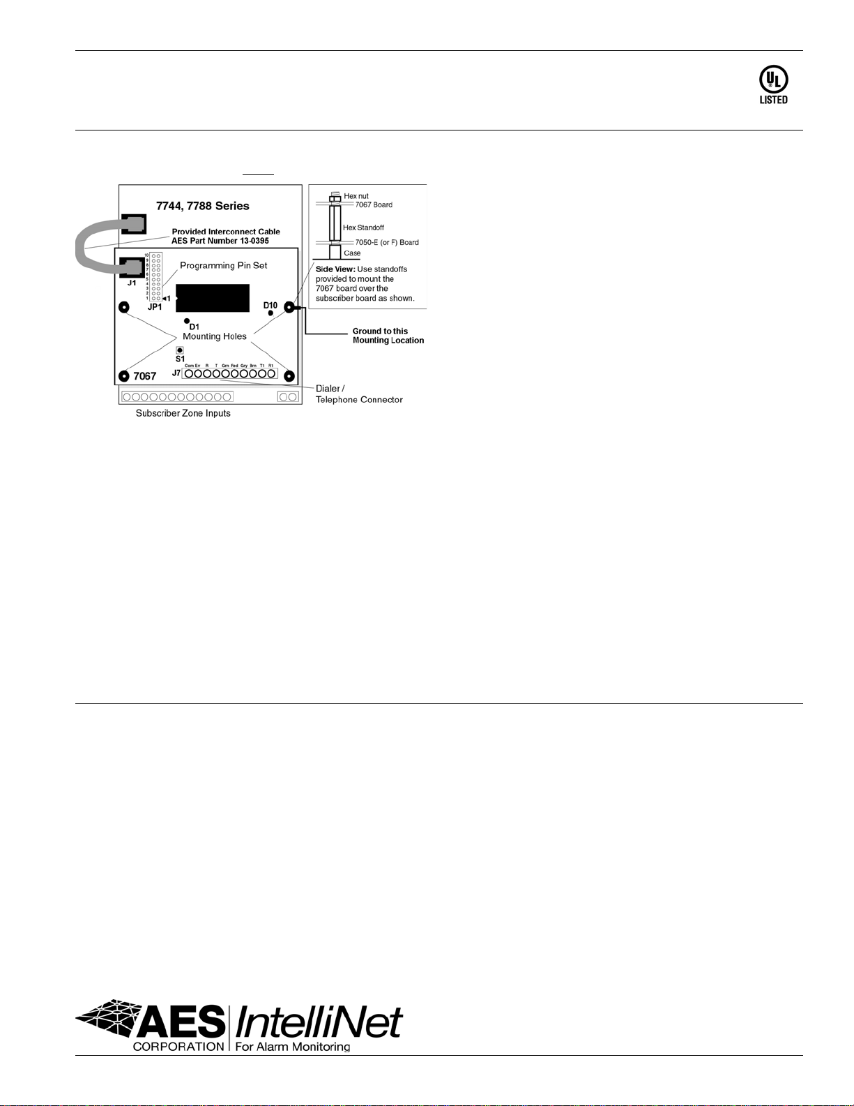
• The 7067 IntelliTAP unit has been investigated by UL for Supplemental Use
Only.
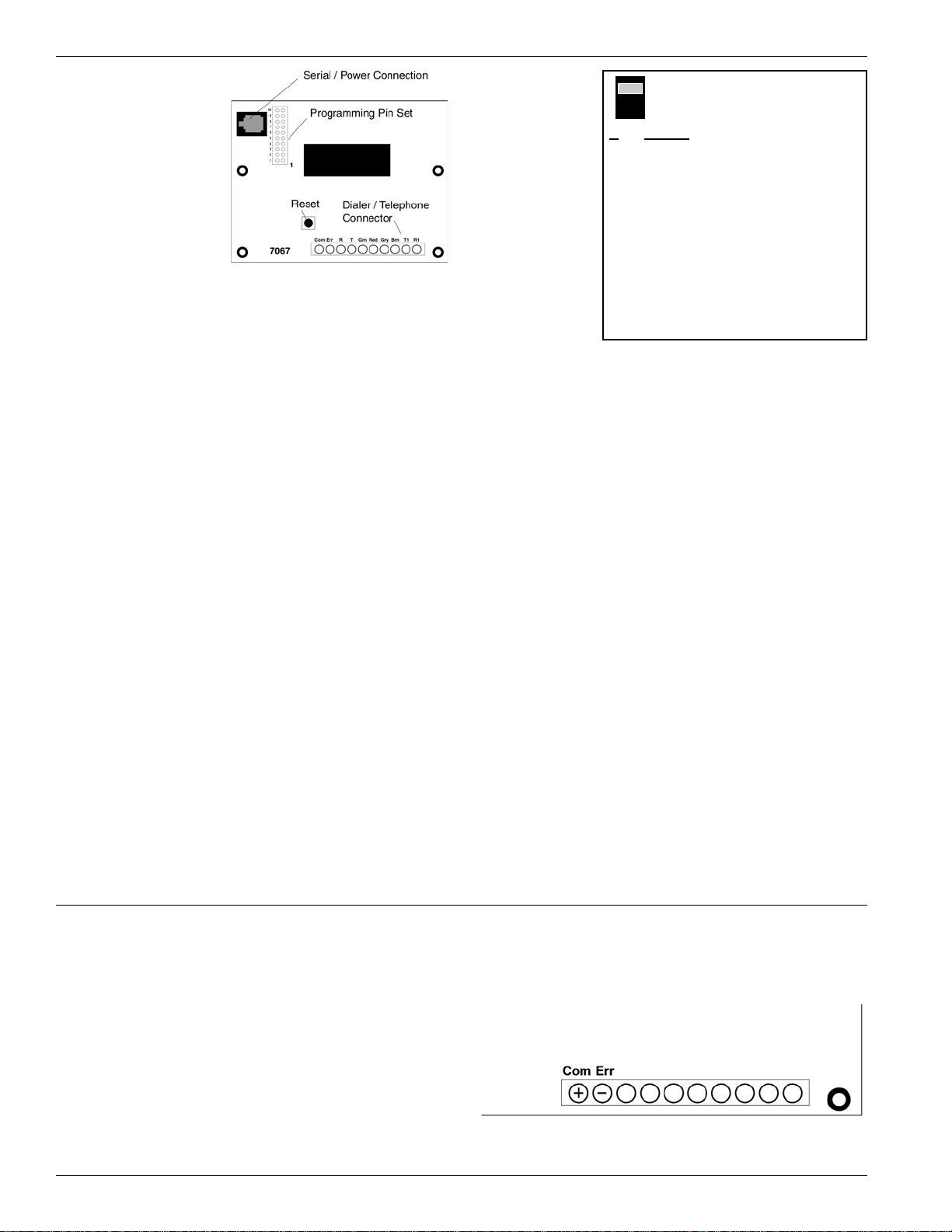
• The 7067 IntelliTAP unit must be mounted inside the AES Subscriber Unit.
The 7067 IntelliTAP unit has been evaluated to the following Standards:
UL:
UL 365 - Police Station Connected Burglar Alarm Units and Systems
UL 1610 - Central Station Burglar Alarm Units
UL 864 - Control Units for Fire-Protective Signaling Systems
TESTPROCEDURE:
• Notify the Central Station that a test is in progress.
• Trip the alarm control panel alarm and trouble circuits.
• Check with the central station that the correct messages were received.
Table of contents
Other AES Recording Equipment manuals