AESSEAL FDU Auto Top Up Manual

YDR-FDU-AUTOPUP-11 11/2016
FDU™ Auto Top Up
Installation Operations & Maintenance Instructions

YDR-FDU-AUTOPUP-11 11/2016
AESSEAL plc, Complex Systems Division, Mill Close, Bradmarsh Business Park, Rotherham, S60 1BZ
Tel: +44 (0) 1709 369966 Fax: +44 (0) 1709 720788 www.aesseal.com
Page 2 of 8
Health and Safety
●This system has been designed for use only as a barrier fluid system for mechanical seals using a suitable
non-hazardous barrier fluid.
●Isolate the process and power on installation, maintenance and decommissioning and ensure that the
system pressure has been relieved before undertaking maintenance.
●The system should only be installed by competent engineering personnel
●Electrical connections must be made in compliance with applicable legislation and / or local requirements by
a competent / qualified electrician.
●If there is any risk of FIRE the system must be fitted with a suitable pressure relief device to prevent over-
pressurisation.
●Pipe relief valves discharge to safe area (when fitted).
●Pressure test the complete system assembly at 1.1x maximum working pressure (duration 5 minutes) and
ensure the system is completely leak free before full operation.
●Do not over-pressurise the system beyond the maximum design pressure. If there is any possibility of over-
pressurisation, the system must be fitted with a suitable protection device.
●Do not exceed the operating limits of the system. Not designed for cyclic loading.
●The system may get hot in operation with risk of burn injury, and suitable engineering controls or guarding
should be adopted where necessary. The risk from Legionella bacteria should be assessed with water barrier
fluids at temperatures between 20°C to 45°C (68°F to 115°F).
●If the barrier fluid becomes contaminated it is recommended that the barrier fluid is replaced taking
necessary precautions. If the contamination is potentially corrosive or damaging to the system remove from
service and contact AESSEAL for technical advice.
Environment
Once the barrier fluid and system have reached the end of its life, it should be disposed of in accordance with local regulations
and with due regard to the environment.
For further information please contact AESSEAL®
YDR-FDU-AUTOPUP-11 11/2016
AESSEAL plc, Complex Systems Division, Mill Close, Bradmarsh Business Park, Rotherham, S60 1BZ
Tel: +44 (0) 1709 369966 Fax: +44 (0) 1709 720788 www.aesseal.com
Page 3 of 8
Installing & Commissioning
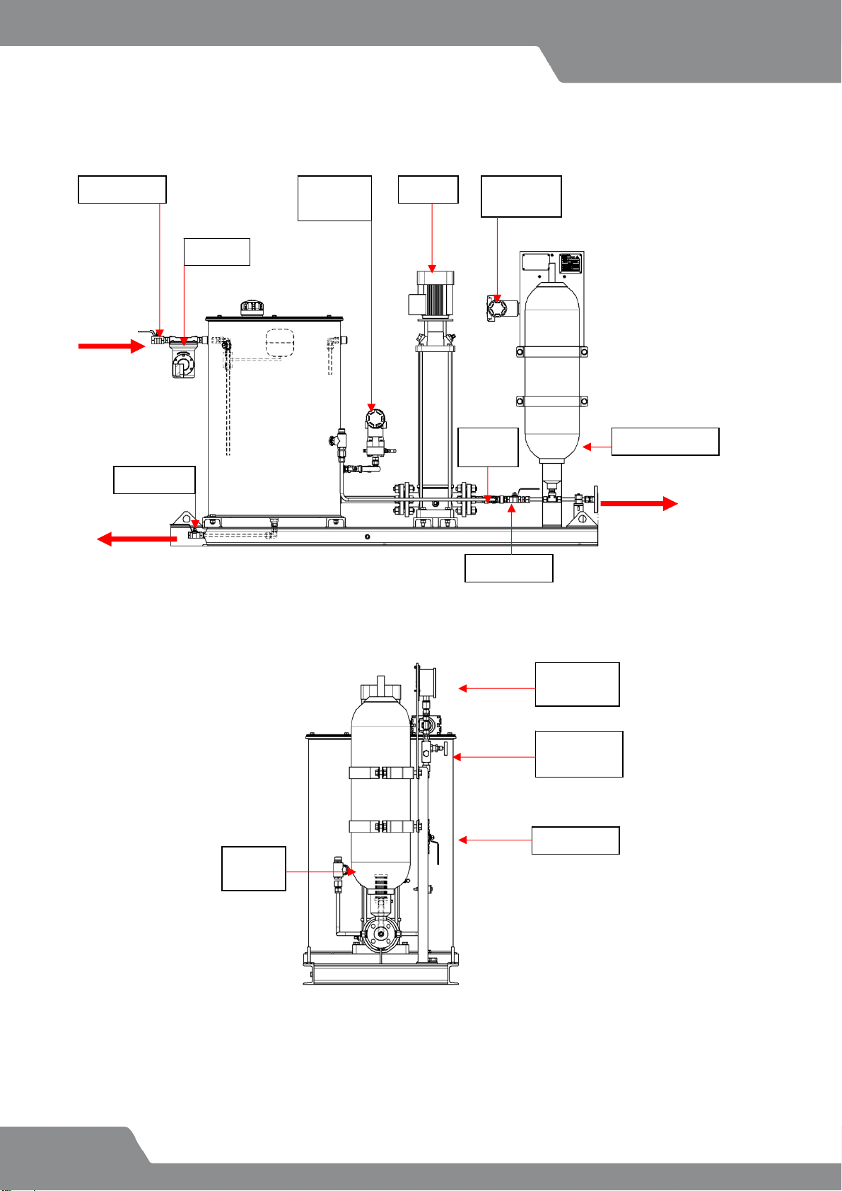
Typical FDU Auto Top Up with Options
Fig.1a Typical layout
* Optional Extras
Please also refer to the drawing contained in the document pack whilst reading these instructions!
Fig.1b Typical layout
Pressure
gauge
Instrument
valve
Relief
valve*
Ball valve
Check
valve
Pump
Accumulator
Level
switch*
Pressure
switch*
Filter*
Ball valve
FILL
SEAL
SUPPLY
DRAIN
Ball valve
Ball valve

YDR-FDU-AUTOPUP-11 11/2016
AESSEAL plc, Complex Systems Division, Mill Close, Bradmarsh Business Park, Rotherham, S60 1BZ
Tel: +44 (0) 1709 369966 Fax: +44 (0) 1709 720788 www.aesseal.com
Page 4 of 8
Fig. 2 Typical P&ID Configurations
Fig.2
Installing & Commissioning
Connections
Ensure all connections are made:
AWater supply
BTank drain
CSupply
DOverflow
●The FDU can be situated on any convenient flat and level surface (such as a concrete floor or plinth), within
close proximity of the seals and support systems.
●Ensure the system is securely affixed to the floor using correct sized bolts inserted through the holes in the
FDU mounting skid.
●Pipe runs may be in hard pipe or suitable flexible hoses, 1” or greater pipe bore is recommended.
●The pipe run should be suitably supported and secured, avoiding potential hazards, such as steam pipes,
walkways etc.
●Check that the pipe runs are connected from inlet and outlet connections to and from the seal support
systems. Ensure that all threaded and compression fittings are tightened. Ensure that all seal supply lines are
fully vented.
●Check that the pipe run is connected to the tank water supply.
●Ensure electrical connections are made to the centrifugal pump/motor set, and ensure correct direction.
●Ensure that any isolation valves between the seal system and the seal (if fitted) are open, and all vents and
drains are closed.
●Ensure any isolation valves fitted to the pressure gauge are open.
●Fill the tank with fresh clean barrier fluid via the filler breather or via inlet fill ball valve to 50mm / 2” below the
overflow and pay careful attention to the level of the fluid when priming the circuit to ensure the pump does
not run dry. N.B. It may be necessary to stop/start the pump to prime the system fully.
YDR-FDU-AUTOPUP-11 11/2016
AESSEAL plc, Complex Systems Division, Mill Close, Bradmarsh Business Park, Rotherham, S60 1BZ
Tel: +44 (0) 1709 369966 Fax: +44 (0) 1709 720788 www.aesseal.com
Page 5 of 8
●Consult Grundfoss pump/motor manual for instructions on how to prime the pump; once the pump has been
primed it may now be started.
Nb. DO NOT start the pump until it has been filled with liquid and vented. Check rotation of motor by means
of the motor fan and label on top of the fan cover.
●Once a reading has been detected on the pressure gauge, turn the pump/motor off, and pre-charge the
accumulator bladder with nitrogen using the supplied charging kit following the F.C.H. accumulator charging
procedures attached below. Note.(The inside of the accumulator must be wet before bladder inflation can
commence)
●Adjust the pressure by adjusting the selected systems pressure control valve, or other, until desired working
settings are reached.
●Ensure the desired pressure is reached by checking the pressure gauge/switch read out.
●Consult Grundfoss instruction manual for any pump/motor technical information.
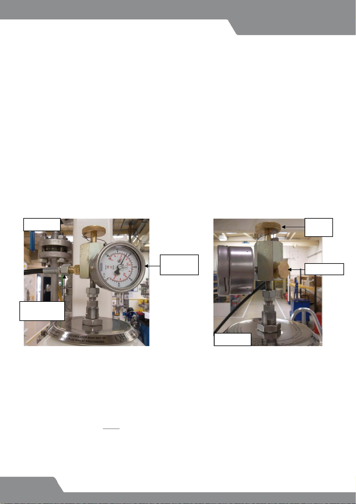
Pre-charging the system
Please also refer to the accumulator charging procedures contained in the document pack
before charging the accumulator
●Confirm the charging kit is compatible with the accumulator, and attach the charging kit to the accumulator as shown in
Figures 3a and 3b
●Connect the charging kit to the nitrogen bottle regulator using the flexible hose.
To attain accurate pressure and avoid damaging the bladder, the following principles need to be
observed, failure to so may result in accumulator operation malfunction.
●The bladder must be inflated slowly in several stages, controlling the pressure by screwing in the nitrogen bottle regulator
knob clockwise, and observing the pressure gauge reading on the charging kit.
Pressure
Gauge
Hand
wheel
Nitrogen
connection
Vent valve
Figure 3a
Figure 3b
Table of contents
Other AESSEAL Industrial Equipment manuals


