AfiMilk AfiAct II User manual

Heat Detection TieStall™– Test Group Guide
s


Preface
Preface
AfiAct II™ Installation Manual
Page i
AfiAct II™
Installation
Product: Reader 2.0
Manual P/N 9440311
Version 2.8
Date Completed –Jan 2020
Afimilk Ltd., Kibbutz Afikim, 15148 Israel
Tel: 972-4-6754812 | Fax: 972-4-6751862
Federal Communications
Commission, USA
Conformité Européenne
(European Conformity)
Standards Institute
of Israel
Ministry of Internal
Affairs and
Communications, Japan
Industry Canada

Preface
Preface
AfiAct II™ Installation Manual
Page ii
Preface Material
About this Manual and Scope
This manual describes the installation of AfiAct II, either as a standalone system or as
part of the larger Afimilk system. For a description of the features and usage of the
AfiAct II system, refer to AfiAct II UM.
Intended Users
This manual is intended forAfimilk authorized technicians, experienced in installing
electrical systems in non-protected environments, for dealers-technicians and farm
technicians.
Contacting Technical Support HelpDesk
Afimilk technical support contact information:
email: [email protected]o.il
Tel: +972-4-675-4824.

Preface
Preface
AfiAct II™ Installation Manual
Page iii
Notes and Certifications
This device complies with FCC Rules Part 15 and with Industry Canada license-
exempt RSS standard(s). Operation is subject to two conditions: (1) This device may
not cause harmful interference, and (2) this device must accept any interference that
may be received or that may cause undesired operation.
Le présent appareil est conforme aux CNR d'Industrie Canada applicables aux
appareils radio exempts de licence. L'exploitation est autorisée aux deux conditions
suivantes :
(1) l'appareil ne doit pas produire de brouillage, et
(2) l'utilisateur de l'appareil doit accepter tout brouillage radioélectrique subi, même
si le brouillage est susceptible d'en compromettre le fonctionnement.
NOTE: The digital circuit of this device has been tested and found to comply with the
limits for a Class B digital device, pursuant to part 15 of the FCC Rules. These limits
are designed to provide reasonable protection against harmful interference in a
residential installation. This equipment generates, uses and can radiate radio
frequency energy and, if not installed and used in accordance with the instructions,
may cause harmful interference to radio communications. However, there is no
guarantee that interference will not occur in a particular installation. If this
equipment does cause harmful interference to radio or television reception, which
can be determined by turning the equipment off and on, the user is encouraged to
try to correct the interference by one or more of the following measures:
•Reorient or relocate the receiving antenna.
•Increase the separation between the equipment and receiver.
•Connect the equipment into an outlet on a circuit different from that to which
the receiver is connected.
•Consult the dealer or an experienced radio/TV technician for help.
Changes or modifications to this equipment not expressly approved by the party
responsible for compliance (Afimilk Ltd.) could void the user’s authority to operate
the equipment.
To comply with FCC RF exposure compliance requirements, the antenna used for
this transmitter must be installed to provide a separation distance of at least 20 cm
from all persons and must not be co-located or operating in conjunction with any
other antenna or transmitter.


Preface
Preface
AfiAct II™ Installation Manual
Page vii
Legal Notice
Copyright
Copyright © 2016 Afimilk Ltd., All Rights Reserved
Disclaimer
This document contains proprietary information of Afimilk Ltd. and may not be
reproduced in any form without the prior written consent of Afimilk Ltd.
No part of this document may be reproduced, translated, stored in a retrieval system
or transmitted in any form and by any means, electronic, mechanical, photographic,
photocopying, recording, or otherwise, without the prior written permission of
Afimilk Ltd.
Information provided in this document is subject to change without notice and does
not represent a commitment on the part of Afimilk Ltd.
All products and company names are trademarks or registered trademarks of their
respective holders.
Software License Terms
The software and the system design is the property of Afimilk Ltd.
It is supplied to the user to be used solely for its stated purposes. It is strictly
forbidden to make copies of the software or transfer it in any way, for any purpose,
to any third party.
In addition to application software specifically developed by Afimilk Ltd., the system
makes use of certain third party utilities and system software. These are licensed for
a single user. They must not be copied in any way, for any purpose, by the user, its
employees, or anybody else.
The license to use the software is granted to the user only for the specific system it is
installed on by Afimilk Ltd., or its authorized distributors and representatives.
The purchaser shall not modify the software in any way.
It is strictly forbidden to usethis product for any purpose other than originally
designated for or stipulated by Afimilk Ltd.
Preface
Preface
AfiAct II™ Installation Manual
Page viii
Conventions
Important information is highlighted in a frame, as explained below:
Environment notice
Hints and recommendations for working efficiently
Actions requiring special attention, to avoid possible damage to equipment
or livestock
Actions requiring special attention to avoid serious bodily injury;
For example, working with high voltage components
Preface
Preface
AfiAct II™ Installation Manual
Page ix
Safety Instructions and Notice
Before installing and operating any equipment, review the safety instructions for any
hazards associated with installation and use of the device. Also, review standard and
local practices for preventing accidents.
The system and its components are powered by electricity from main power supply.
This power supply is sufficient to cause serious personal injury or even death.
Only a (local state) licensed electrician should install power cables and power supply
units.
Use only a correctly rated power cable that is certified, as appropriate, for the
country of operation.
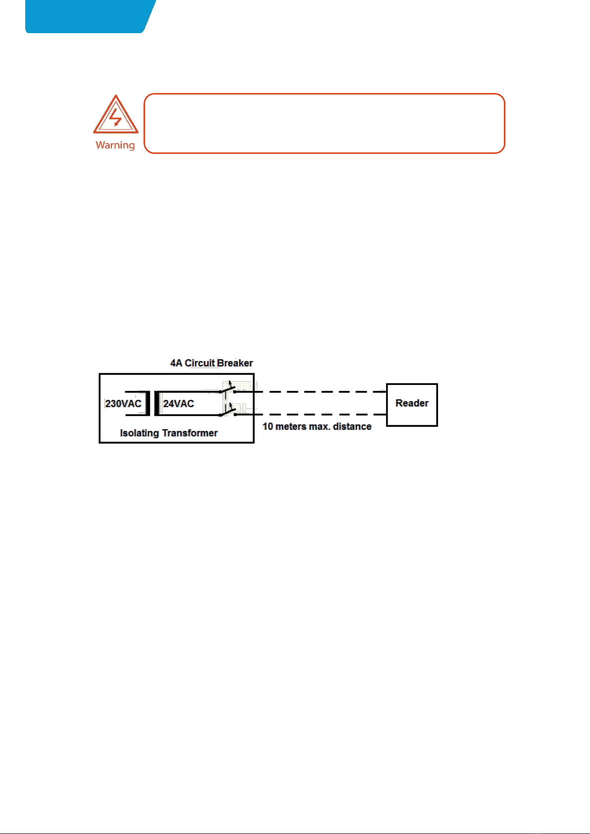
The AfiAct II must be powered by an external isolating transformer (output 21.6 -
27.5Vac, 75 VA maximum, certified as LPS according IEC 60950-1 clause 2.5) with an
accessible circuit breaker and double isolated from mains.
•Read this manual carefully. Proper handling of the equipment is the basis for
correct functioning.
•Only technicians who are skilled and authorized by Afimilk, dealer
technicianstogether with the farm staff may carry out installation of the
equipment.
•The customer is fully responsible for any changes made, either in the system
configuration or in the software application data, by the customer or by the
customer’s agent.
•Afimilk will not be held responsible directly or indirectly for any damage caused
to the customer and/or to a third party and/or to the animals, by an action
and/or change and/or omission performed in the AfiAct II™ system, either by the
customer or by the customer’s agent, directly and/or indirectly.
Electrical connections must only be performed by a certified electrician.
The installation must be performed in accordance with current norms and
regulations as well as local and national rules.

Preface
Preface
AfiAct II™ Installation Manual
Page x
•Afimilk recommends that the customer call for a full system inspection by a
qualified technician authorized by Afimilk every six months.
•It is the responsibility of the operator to install, operate, and maintain the system
in accordance with all applicable laws, codes and regulations.
•The equipment must be used only for the described purpose.
•This system has been checked for viruses prior to supply.If in the course of a
service call, a virus is detected, removal of the virus, and any software or
hardware repairs resulting from it, will be charged to the purchaser.
The system and its components are powered by electricity from a main power
supply. To avoid personal injury, danger of fire, and possible damage to equipment
and materials, all work on electrical and electronic circuits should be done following
these basic safety procedures:
•Power to all Afimilk devices must be supplied through an accessible, well-marked
circuit breaker (usually placed on the power transformer).
•Before conducting work on any Afimilk device, make sure power to devices is
switched off at the circuit breaker (usually placed on the power transformer).
•Remove power from the circuit or equipment prior to working on it. Never
assume the circuit is off; check it with a multimeter.
•In case of electrical fire, switch off the circuit and report it immediately to
appropriate authority.
•Stay away from live circuits. Do not work on or make adjustments when the
power switch is on.
•Never switch on equipment in the presence of water leakage.
•Work in clean, dry areas. Avoid working in damp or wet locations because this
increases the chance of electrical shock.
•Wear only nonconductive shoes to lessen the possibility of electrical shock.
•Remove all rings, wristwatches, bracelets, and similar metal items. Avoid working
in clothing that contains exposed metal zippers, buttons, or other types of metal
fasteners. The metal can act as a conductor, heat up, and cause a bad burn.
•High voltage surges and other power irregularities can cause extensive damage
to a system. It is the responsibility of the operator to provide a power protection
system.
Do not dispose of WEEE as unsorted municipal waste!

Preface
Preface
AfiAct II™ Installation Manual
Page xi
List of Terms and Abbreviations
Term/Abbreviation
Description
RPU
Tag Reading/Programming Unit
AfiAct II
AfiFarm module for generating cow database and
providing general fertility reports.
DIM
Days in Milk
ID
Identification
PC
Personal Computer
PD
Pregnancy Diagnosis
RF
Radio Frequency
LR
Long Range radio i.e. 916/868 MHz, communication
between Reader and tags
SR
Short Range radio i.e. 200/80 KHz
RT
Real Time system
RTMS
Real Time Setup module
RTG
Real Time GUI module - AfiControl
RTC
Real Time Station Controller module
RPM
Revolutions per Minute
Opcode
Operation Code
AP
WiFi Access Point (antenna)
WLAN
Wireless Local Area Network - links two or more devices
using wireless distribution, providing a connection through
an access point to the Internet.
Tx
Transmit
IM
Installation Manual
Referred Documents
PN
Document Name
9140233
Tag Reader& Tag RPU user guide
9040946
SR Opcodes (for RPU programming)
9040953
AfiFarm Installation Manual
5096003
AfiFarm Configuration Manual
9040954
AfiFarm Integration and Prerequisites
9440312
AfiAct II User Manual
9040952
AfiAct II Software Upgrade Instructions (R1 →R2)

Preface
Preface
AfiAct II™ Installation Manual
Page xii
Revision History
Version
Date
Description
1.00
Oct 2013
Revision one.
1.2
Oct 2013
Add FCC Approvals
2.0
Feb 2014
Update WIFI spec 2.2
PC requirements 2.3.1
re-locate RT quick-start (after RT installation) 4.2
add tag-activation runtine 6.1
correct troubleshooting flow for disconnection, 7.1
Update antenna names 1.3.1
update location of RID label,
correct wifi setings 4.4,
remove tag survey section (covered by other sections),
add backup settup,
add db backup and restore.
2.1
Mar 2014
Correct supported Windows version, section 2.4.1
2.2
Mar 2014
Add Japan radio regulation certification (preface).
2.3
Sep 2014
Add Circuit Breaker warning, see Safety instructions on page ix
Replace reader mounting plate and rod
2.4
May 2015
Installation and configuration - screens and process updated.
RPU flow updated
New template implemented
2.5
Sep 2015
Comply with safety regulations (updates in section 1.5)
2.6
Dec 2015
Replace Reader’s blue wire + extension by the new white wire
Correct names (RT Studio→AfiControl)
Update screens and flow
Update safety instructions to suit new regulations
Update AfiTag arrow pictures
2.7
May 2016
New Reader version 2.0, with internal antennas
2.8
Dec 2019
Updated to support AfiCollar.
Updated to work with Windows 10.

Preface
Preface
AfiAct II™ Installation Manual
Page xiii
Table of Contents
Preface Material ......................................................................................................................................ii
Table of Contents .................................................................................................................................xiii
1Introduction ................................................................................................................................ 1
1.1 Principle of Operation ......................................................................................................... 1
1.2 Supported Scenarios ........................................................................................................... 2
1.3 AfiAct II Components .......................................................................................................... 2
1.3.1 Reader Box Components .................................................................................................. 3
1.3.2 Electricity Box Components .............................................................................................. 4
1.3.3 Tag Types ......................................................................................................................... 4
1.4 AfiAct II
Reader –Indicators and I/Os................................................................................. 5
1.4.1 Front Panel - LED Indications ........................................................................................... 5
1.4.2 Back Panel –Inputs and Outputs ..................................................................................... 7
1.4.3 Reader box - Attributes Label ........................................................................................... 8
1.5 AfiAct II Reader Power Specifications ................................................................................. 8
1.6 System Installation Overview.............................................................................................. 9
2Prerequisites and Site Planning................................................................................................. 10
2.1 Determine Reader Mounting Location.............................................................................. 10
2.2 Setup Network and Power Coverage ................................................................................ 12
2.3 Prepare the PC Environment ............................................................................................. 13
2.3.1 Verify Operating System, Processor & Memory ............................................................. 14
2.3.2 Network Connections ..................................................................................................... 19
2.3.3 Additional Windows OS Preparations ............................................................................ 21
2.3.4 Verify System is Prepared ............................................................................................... 28
3Install and Set AfiAct II Software............................................................................................... 29
3.1 General Notes ................................................................................................................... 29
3.2 Set & Initiate the Installation Wizard................................................................................ 30
4Initial Reader Communication................................................................................................... 34
4.1 Connect the Reader to the Wired Network....................................................................... 35
4.2 Set AfiControl (Quick Start)............................................................................................... 37
4.2.1 Navigating AfiControl Tool ............................................................................................. 38
4.2.2 Determine the Required Sampling Sessions ................................................................... 40
4.2.3 Set Mandatory System Parameters ............................................................................... 42
4.2.4 Faulty Tag Check ............................................................................................................ 57
4.3 Verify Reader & AfiControl Communication ..................................................................... 59
4.4 If Needed: Set Wi-Fi Communication ................................................................................ 59
4.4.1 Set Reader to use Wi-Fi settings different than Default ................................................. 60
5Mount the Reader..................................................................................................................... 64
5.1 Mount the Power and Electricity Boxes ............................................................................ 65
5.2 Mount the Reader on the Pole.......................................................................................... 68
5.3 Connect the Reader to Power ........................................................................................... 71

Preface
Preface
AfiAct II™ Installation Manual
Page xiv
6Tag Management ...................................................................................................................... 72
6.1 AfiAct II Tags’ Transmission Test....................................................................................... 73
6.1.1 Activating and Validating AfiTag Transmission ............................................................. 73
6.1.2 Activating and Validating AfiCollar Transmission .......................................................... 75
6.2 Perimeter Coverage Validation......................................................................................... 77
6.2.1 Perimeter Coverage Validation for AfiTags .................................................................... 77
6.2.2 Perimeter Coverage Validation for AfiCollars ................................................................ 77
6.3 Attach Tags ....................................................................................................................... 78
6.3.1 Attach AfiTags to the Cows ............................................................................................ 78
6.3.2 Attach AfiCollars to the Cows ......................................................................................... 81
6.4 Replace and Re-Use Tags.................................................................................................. 82
6.4.1 Remove AfiTag II from the Cow ...................................................................................... 83
6.5 Store Tags ......................................................................................................................... 85
6.5.1 Storage Location ............................................................................................................ 85
6.5.2 Storage Position ............................................................................................................. 85
7Fault Identification and Troubleshooting.................................................................................. 86
7.1 Reader Connection to AfiControl or Network Fault .......................................................... 87
7.2 Tag Problems .................................................................................................................... 88
7.3 Reader and Tag Communication Faults ............................................................................ 89
7.4 Reader’s Luci Cannot be Accessed .................................................................................... 89
7.5 Back-to-Back Connection .................................................................................................. 90
7.6 Region Transmission Setup ............................................................................................... 90
7.7 AfiFarm Installation Problems .......................................................................................... 91
Appendix A: Set Laptop’s Static IP........................................................................................................ 92
Appendix B: RPU Tool for Tag Management ........................................................................................ 97
Appendix C: AfiControl Summary....................................................................................................... 102
Appendix D: TieStall............................................................................................................................ 109
Appendix E: Enter Herd’s Data ........................................................................................................... 111
Introduction
Chapter 1
AfiAct II™ Installation Manual
Page 1
1Introduction
AfiAct II is an estrus and fertility monitoring system that provides at a glance full
picture of cows and heifers in estrus. The monitoring system provides thorough
tracking of the fertility-related data for the dairy farm herd. It can be implemented
either as a standalone system or as part of a comprehensive Afimilk system.
This is done by collecting cows’ physical behavior and aggregating them with
events information to generate heat lists, fertility reports, and fertility disorder
alerts.
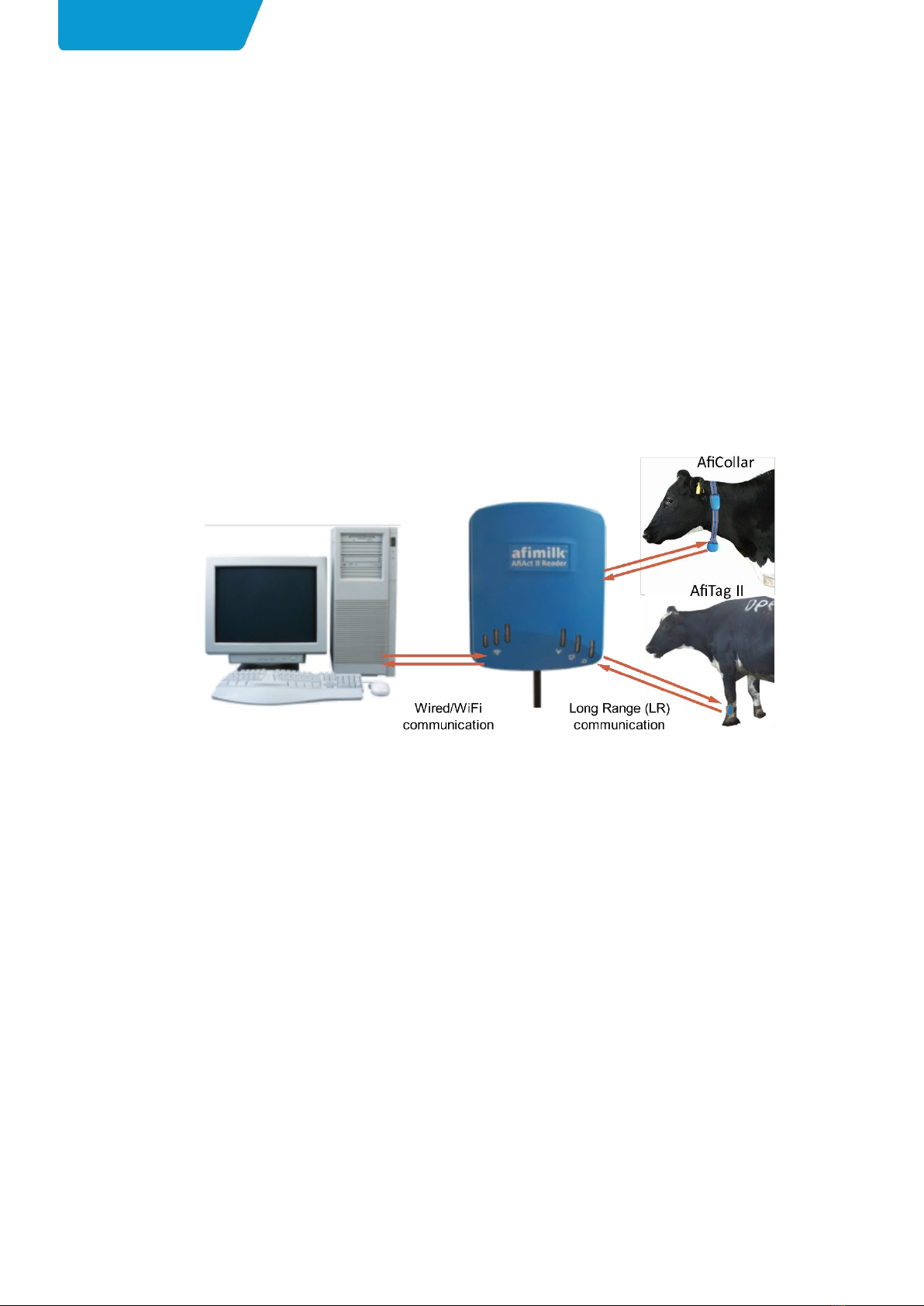
1.1 Principle of Operation
The following diagram shows the data flow in the AfiAct II system.
Figure 1: AfiAct II system data flow
AfiAct II uses Long Range (LR) communication to collect data from cow tags (AfiTag
II sensors or AfiCollar sensors) and transfers the information via a standard
network (IP based Wi-Fi or wired communication) to a PC based analysis.
Tags are placed on the cows. Each tag contains the unique ID of each cow, and
records different aspects of its activities, as follows:
•AfiTag II leg tags –records the cow's number of steps, standing time, rest time
and bout.
•AfiCollar neck tags –records the cow's eating and rumination times.
The tags use LR (Long Range) RF (Radio Frequency) communication to send this
data periodically (every pre-defined time-interval, default is 15 minutes) to an
antenna located inside the AfiAct II Reader device (two antennas that provide
optimal coverage).
AfiAct II Reader collects data from the cows’tags which are within its receiving
range. The Reader uses either wired or Wi-Fi communication to send the data to
the PC for analysis (2 internal antennas are for Wi-Fi, when used).

Introduction
Chapter 1
AfiAct II™ Installation Manual
Page 2
The AfiAct II software, located on the PC, uses the collected activity data of each
cow to calculate when the cow is in estrus and find the best time for breeding. The
application generates reports and alerts the farmer.
The communication used by the entire system complies with local regulations and
safety tests, corresponding with the ‘home appliance’category.
1.2 Supported Scenarios
This document describes the following scenarios:
•Installation
•Upgrade from R1 –see AfiAct II software upgrade instructions
Both scenarios use a single computer (no custom installation)
1.3 AfiAct II Components
The following table provides a list of the basic AfiAct II system elements. For
specific part numbers, refer to the detailed tables of each element.
Table 1-1. System Components
Picture
Name
Description
PNs –see:
AfiAct II Reader 2.0
(including nounting
brackets)
TheReader is the interface
between the tags and the
AfiAct II Software. Internal
antennas allow Reader-tag
communication, & Reader-
PC Wi-Fi communication.
1.3.1
AfiAct II software
program (AfiFarm 5.4 +
AfiControl module)
CD with PC software to
control the system:
AfiFarm 5.4 for user
interface;
AfiControl module for
data collection from the
Reader.
4196000A2
Introduction
Chapter 1
AfiAct II™ Installation Manual
Page 3
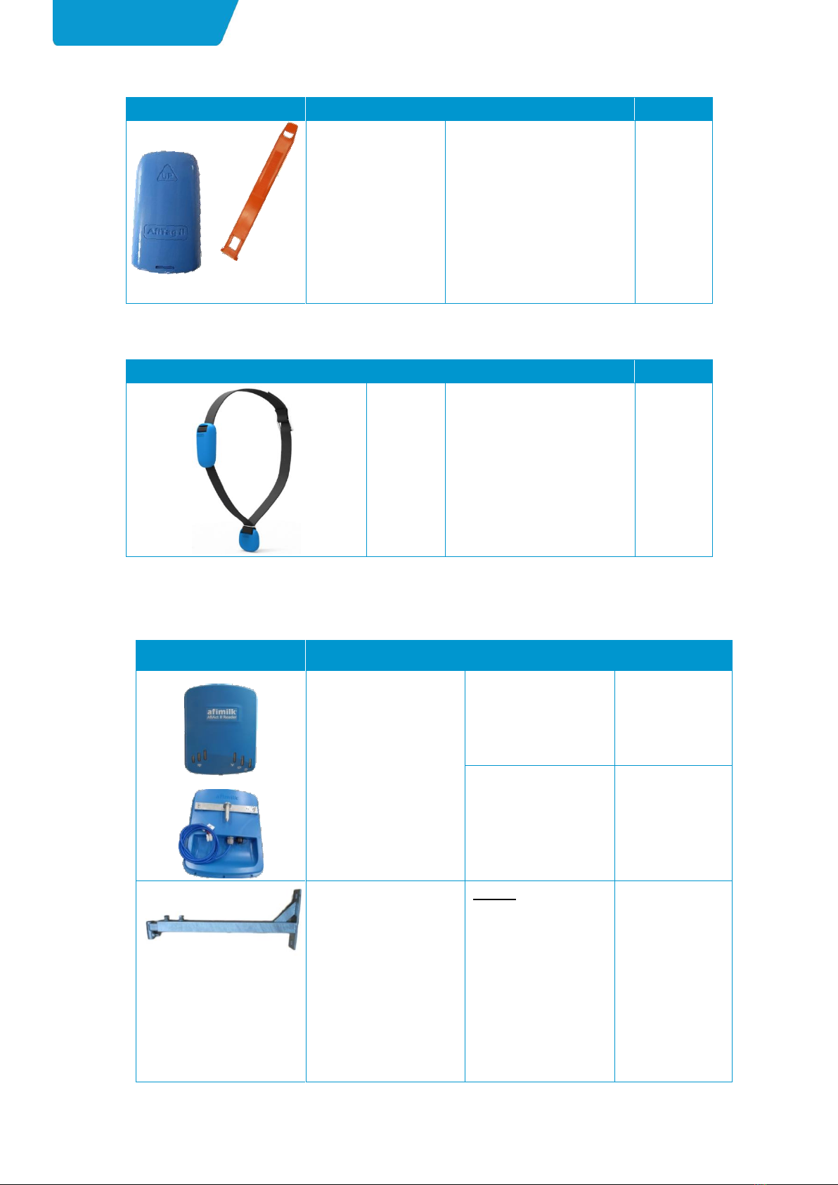
Table 1-2. AfiTag II Components
Picture
Name
Description
PNs –see:
AfiTag II
(40096xx)
Afimilk’s leg-tag, including the
attachment strap.
A tag should be attached to
every cow participating in the
AfiAct II group.
1.3.3
Table 1-3. AfiCollar Components
Picture
Name
Description
PNs –see:
AfiCollar
Afimilk's neck-tag, including
attachment strap and weight.
A tag should be attached to
every cow participating in the
AfiAct II group.
1.3.3
1.3.1 Reader Box Components
Table 1-4.Reader Box Components
Picture
Name
Description
PN
AfiAct II Reader 2.0
International (907-928
MHz)
4256200;
Backward
compatibility
Reader 4256000
Europe (868 MHz):
4256201;
Backward
compatibility
Reader 4256001
Bracket arm
Bracket
(screws for wall
connection –not
supplied. The fasteners
must be determined by
the installer, according
to conditions: surface
(e.g. concrete vs wood
vs steel, etc.) and other
specific variables.
9030050
Introduction
Chapter 1
AfiAct II™ Installation Manual
Page 4
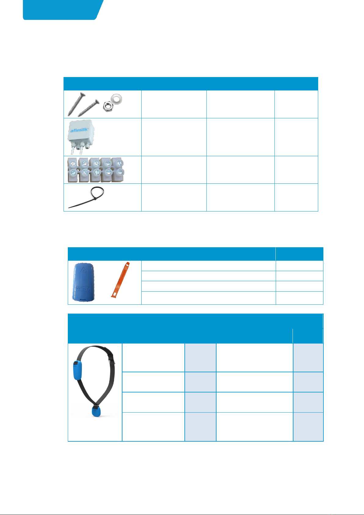
1.3.2 Electricity Box Components
Table 1-5.Electricity Box Components
Picture
Name
Description
PN
Screws and nuts
Not provided!
To be supplied by
installation technician.
Electrical connection
box for AfiAct II Reader
Not provided!
To be supplied by
installation technician.
4085851
Electrical terminal
block
Arrives connected to
Reader’s blue cable.
9020201
Cable ties
Not provided!
To be brought with
technician kit.
1.3.3 Tag Types
Table 1-6.Tag Types
Picture
Description
PN
AfiTag II, Type A, 200 KHz SR, 916 MHz LR
4009600
AfiTag II, Type A, 200 KHz SR, 916 MHz LR, Israel
4009680
AfiTag II, Type B, 80 KHz SR,868 MHz LR
4009610
AfiTag II, Type E, 200 KHz SR, Japan 922.4 MHz LR
4009650
Image
Primary P/Ns
Secondary P/Ns
Description
PN
Description
PN
AfiCollar
907MHz_200KHz -
ASSY.*
8002020*
AfiCollar 908.1MHz_200KHz -
ASSY
8002070
AfiCollar 868.1MHz _
80KHz - ASSY.*
8002030*
AfiCollar 868.3MHz _ 80KHz -
ASSY
8002040
AfiCollar 868.1MHz _
200KHz –ASSY*
8002050*
AfiCollar 868.3MHz _ 200KHz
–ASSY
8002060
AfiCollar
915.5MHz_80KHz –
ASSY*
8002080*
AfiCollar 915.7MHz_80KHz -
ASSY
8002090
By default, dealers should order the primary P/Ns; however, if there is a problem
with the primary sub-g frequency (such as a nearby farm/s, known RF noises, etc.),
then dealers should order their secondary sub-g frequency.
Other manuals for AfiAct II
1
Table of contents
Other AfiMilk Farm Equipment manuals


