AFL FlexScan FS300 User manual

FlexScan®FS300 QUAD OTDR
With SmartAuto®and LinkMap®
User’s Guide
Test & InspectionTest & Inspection
www.AFLglobal.com

2
Table of Contents
Safety Information..........................................3
Apple Inc. Legal Notice ......................................3
Hardware Overview .........................................4
Controls, Display, Interfaces ......................................4
Battery Charging...............................................5
Understanding Battery Charge Status ...............................5
Configuring FlexScan to Auto-Off ..................................5
User Interface Overview .....................................6
Test Modes and Features Summary .................................6
Utility Modes and Features Summary................................6
General Settings ...........................................7
Common Functions in OTDR Test Modes.........................12
Live Fiber Detection.............................................12
Launch Quality Check ...........................................12
OTDR Test Results Viewers .......................................13
SmartAuto®OTDR ..........................................14
Network Type .................................................14
Test Wavelength ...............................................14
Fiber Type . . . . . . . . . . . . . . . . . . . . . . . . . . . . . . . . . . . . . . . . . . . . . . . . . . . . 15
Viewing and Configuring Fiber Type ..............................15
Launch & Tail Cords.............................................16
Pass/Fail Rule .................................................16
Viewing and Configuring Pass/Fail Rule ...........................17
To Start SmartAuto OTDR Test.....................................18
Understanding LinkMap®View Features .............................19
Understanding Event Table View Features ............................20
Understanding Trace View Features ................................21
Expert and Real-time OTDR ...................................23
Understanding Expert and Real-time OTDR Settings ....................23
Expert and Real-time OTDR Setup ..................................24
Test Sequence in Expert OTDR Mode................................25
Test Sequence in Real-time OTDR Mode .............................25
Light Source and Power Meter Operation........................26
Light Source Settings and Features .................................26
Power Meter Settings and Features .................................26
Inspecting Fibers with FOCIS Series Inspection Probe and FlexScan...27
FOCIS Flex Inspection Probe Overview...............................27
Pairing FlexScan with FOCIS Flex Inspection Probe .....................28
Configuring Auto-Send ........................................29
Inspecting Optical Connectors .....................................29
File Manager ..............................................30
Saving Results.................................................31
Saving Results for Bi-directional Reporting ...........................31
Saving Results - Auto-Save & Auto-Send .............................32
Viewing Saved Test Results .......................................33
Deleting Projects/Jobs/Fibers......................................33
Transferring Results to a PC via USB ............................34
Back Up Saved Results to USB Memory .........................34
Printing Results to PDF ......................................35
How to View Device Information ..............................36
General Information ........................................37
Contacting Customer Service......................................37
Warranty Terms and Conditions....................................37
©2020 AFL, all rights reserved. FS300-00-1000 Revision AB, 2019-07-23

3
Safety Information
WARNING! Use of procedures or adjustments other than those specied herein may result in hazardous radiation exposure.
850/1300 nm MM OTDR/OLS port
1310/1550 nm SM OTDR/OLS port
This is a CLASS I LASER output.
VFL port This is a CLASS IIIa/3R LASER output.
Avoid exposure to the beam!
NOTE! FlexScan OTDRs equipped with Bluetooth/WiFi (option W1) contain the following two Bluetooth / WiFi Transmitter Modules:
FCC ID: X3ZBTMOD8 FCC ID: Z64-WL18DBMOD
IC: 8828A-MOD8 IC: 451I-WL18DBMOD
WARNING! Use only the specied AC adapter. Use of another type of AC adapter can damage the instrument and create the danger of re and electrical shock.
WARNING! To avoid the danger of re and electrical shock:
• Never use a voltage that is different from that for which the AC adapter is rated.
• Do not plug the unit into a power outlet that is shared by other devices.
• Never modify the power cord or excessively bend, twist, or pull it.
• Do not allow the power cord to become damaged.
• Do not place heavy objects on the power cord or expose it to heat.
• Never touch the AC adapter while your hands are wet.
• Should the power cord become seriously damaged (internal wiring exposed or shorted), contact the manufacturer to request servicing.
• CAUTION! Do not run any tests or perform functions that activate a FlexScan laser unless ber is attached to the corresponding port.
• CAUTION! To avoid serious eye injury, never look directly into the optical outputs of ber optic network equipment, test equipment, patch cords, or test
jumpers. Refer to your company’s safety procedures when working with optical systems.
• NOTICE: Except user replaceable battery, FlexScan OTDR contains no user-serviceable parts, it must be returned to AFL or authorized agents for repair and
calibration.
• IMPORTANT: Proper care in handling should be taken when using any precision optical test equipment. Scratched or contaminated optical connectors can
impact the performance of the instrument. It is important to keep the dust caps in place when the unit is not being used.
• IMPORTANT: Always clean OTDR port and any mating connectors using approved cleaning supplies (e.g. One-click cleaner) before mating the connectors.
• CAUTION! Power levels in excess of +10 dBm may damage OTDR optics. Do not connect OTDR to network connectors where received power level may exceed
+10 dBm. If high power levels are suspected, verify power level by connecting to OPM and measuring received power level.
Apple Inc. Legal Notice
AirPlay, iPad, iPhone, iPod, iPod classic, iPod nano, iPod touch, and Retina are trademarks of Apple Inc., registered in the U.S. and other countries. iPad Air, iPad
mini, and Lightning are trademarks of Apple Inc.

4
Hardware Overview
Controls, Display, Interfaces
Ref Feature Description
1Power button Press to power FlexScan OTDR on/off.
2Power port (5 VDC) This is interface for the AC power adapter/charger.
3AC/Charger indicator Illuminates when AC is connected and indicates battery charging status.
• RED light = rechargeable battery is charging.
• GREEN light = rechargeable battery is fully charged.
4USB host port This USB port may be used to connect USB Flash Drive for data storage, results backup or to update
FlexScan software.
5Micro-USB function port With the supplied USB cable, this port may be used to connect OTDR to a USB host port on a PC to upload
stored results, PDF printouts and captured screen images.
6Multimode OTDR/Source port This is a CLASS I LASER output. Multimode OTDR/Light Source port.
7Single-mode OTDR/Source port This is a CLASS I LASER output. Single-mode OTDR/Light Source port.
8VFL port This is a CLASS IIIa/3R LASER output. Avoid exposure to the beam!
The VFL (visual fault locator) port is a 635 nm (visible red) laser. Used for short-range fault-location.
9Power meter port Optical Power Meter port. Used for power (dBm, W) or loss (dB) measurements.
10 Touchscreen display 5” 800 x 480 Color Backlit LCD and Gesture-Recognition Touchscreen.
11 Home button Press to access the Home screen.
12 Test start/stop button Press to start a new test; or, if a test is running, stop the current test.
13 VFL button Use the VFL button to control the VFL laser:
Press and hold ~ 1 sec to enable VFL at ~2 Hz ash rate
Press and hold ~ 2 sec = CW
Press and hold ~ 1 sec to switch off
14 VFL indicator When the VFL port is active this indicator illuminates as follows:
Flashing RED = VFL ashing at ~2 Hz rate
Solid RED = VFL on CW
OFF = VFL is off
10
34
5
2
1
79
8
6
11
12
13
14

5
Battery Charging
You may charge the battery while your FlexScan is switched on or off by attaching the supplied AC charger.
• Plug the included AC charger into AC outlet.
• Connect charger plug to the Power port.
• AC/Charger indicator will illuminate to indicate charging status as follows:
–RED - Charging battery
–GREEN - Fully charged
–OFF - AC disconnected
• FlexScan charges while operating.
• A fully-charged battery operates for approximately 12 hours of typical use.
Understanding Battery Charge Status
When FlexScan is ON, battery icon shown on the display indicates battery status as follows:
- Battery fully charged
- Battery partially charged
- Battery discharged
- Battery charging
Battery fully charged, Battery partially charged, and Battery discharged symbols will only be shown when unit is operating without being connected to AC.
Configuring FlexScan to Auto-Off
The Auto-Off feature is available for conserving battery power on your FlexScan.
To Configure the Auto-Off Timer:
• Turn your FlexScan On.
• From the displayed Home screen , touch Settings menu.
• In the Settings menu, locate the Auto Off Timer option.
• Touch the Auto Off Timer eld to display the settings sub-menu.
• Select the desired power save option (Never, 5 min, 15 min).

6
User Interface Overview
Home Screen Features
The Home screen is the FlexScan’s Main screen that is displayed at startup. While in any other screen, return to Home by either pressing the Home button or
touching and holding (if available) the Back soft key. This screen contains menus of Test and Utility modes that allow users to set test parameters, select user
preferences, manage saved test results, congure general settings and perform other non-test functions.
Test Modes and Features Summary
1. SmartAuto®OTDR (recommended): Congure and run SmartAuto OTDR test using multi-pulse acquisition.
2. Expert OTDR: Congure and run Expert OTDR test with averaging.
3. Real Time OTDR: Congure and initiate OTDR test with real-time updates.
4. Power Meter & Source (OPM + OLS): Enable light source and/or measure optical power.
5. Connector Inspection: View connector inspection results received via Bluetooth from FOCIS Flex, FOCIS Duel, or FOCIS Lightning probe.
6. My Projects: Touch to view test results.
7. USB: Touch to enable le transfer. Enabling this mode allows the user to connect to a PC to upload results to the PC or download software updates from the
PC.
8. Last: Touch to view the most recent test results.
9. Settings: Touch to access General Settings menu that contains Unit settings, user preferences, and common OTDR settings.
Utility Modes and Features Summary
10. Menu: Touch to view Device Information screen.
11. Screen Title: Name of the currently displayed screen.
12. USB: Indicates external USB memory stick detected.
13. Time of day.
14. Battery Icon: Indicates battery charge level.
6
4
5
2
1
3
8910
7
11
13 14
12

7
While in the General Settings screen, select and view or edit settings as follows:
Language: touch to select from available languages (depends on installed language pack).
Distance Units: select
–kilometers
–meters
–kilofeet
–feet
–miles
Note: Link and ber section Loss/distance will be reported as:
–dB/km (distance units = m or km)
–dB/kft (distance units = ft or kft)
–dB/mi (distance units = mi)
WiFi: touch to congure WiFi
–Enable WiFi
–Scan for networks
–Select from available networks
–Connect & enter password if required
General Settings
While in the General Settings screen:
• Touch the desired setting eld (e.g. Language) to display a sub-menu.
• Touch Left / Right Arrows to display additional General Settings screen.
• Touch Back to return to the previous menu.

8
Speaker Volume:
• If disabled, touch the on/off control to turn the Speaker on.
• Touch and/or touch and drag the adjustment slider right/left to increase/decrease the Speaker volume.
• Or, press [-] / [+] controls for precise adjustments of 10% by step.
• Press Done to save changes and return to the General Settings screen.
Date and Time:
• Enable / Disable 24 hour format.
• Touch current Date & Time to edit.
–From the displayed sub-menu, touch the desired Time/Date parameter to enable it: hours, minutes, AM/PM (if 24-hour format disabled), year, month, day.
–Use [-] / [+] controls to change (increment or decrement) the selected parameter value.
–Touch Done to save changes and return to the General Settings screen.
–Touch Cancel or Back to return to Settings menu without saving edits.
Auto Off Timer: Touch to display a sub-screen and select Auto Off option: Never, 5 min, 15 min.
Bluetooth: Touch to display a sub-screen and enable Bluetooth.
• Enable Bluetooth, touch the on/off control
• Select Pair New Device to scan for and pair to another Bluetooth device
–Select Scan to discover devices, then select device from list to pair
• Select Previously Connected to view and select from list of previously connected devices
–Touch a previously connected device to reconnect; Solid star ( ) indicates selected device

9
Screen Brightness and Auto-dim:
• Touch the on/off control to enable/disable the Auto Brightness feature.
• When the Auto Brightness feature is disabled, you may adjust Brightness by touching and/or touching and dragging the adjustment slider right/left to increase/
decrease the Brightness value. Or, you may press the [-] and [+] controls for precise adjustments of 10% by step.
• When the Auto Brightness feature is enabled, you may adjust several parameters:
–Auto-dim: Select Sleep icon and adjust slider right/left or use [+] / [-] controls to increase or decrease backlight dim setting
–Brightness: Select Bright icon and adjust slider right/ left or use [+] / [-] controls to increase or decrease brightness
–Timer control: Select and adjust time delay after last touchscreen action before display auto dims (if Auto Brightness enabled)
–Press Done to save changes and return to the General Settings screen.
Touch Left / Right Arrows to display additional General Settings screen.
Auto-Save and Auto-Send:
• Touch Auto-Save / Send to enable/disable Auto-Save or Auto-Save & Send
• Touch desired option:
–Disable Auto-Save & Send
–Enable Auto-Save only
–Enable Auto-Save & Send
• If Auto-Save or Save & Send selected, congure Project, Fiber Group, Fiber# where results are to be saved
• Touch Done when nished conguring Project, Fiber Group, and Fiber#
• Current Auto-Save / Send conguration is displayed

10
Launch Quality Check: Touch the on/off control to enable/disable check of the OTDR connection quality at start of each OTDR test.
• Poor launch quality is reported when excess loss or excess reection is detected at the OTDR connection.
• Poor launch quality may result from:
–Dirty or damaged OTDR and/or jumper connectors – Always clean OTDR port and jumper connectors before connecting to OTDR and network-under-test
–Mismatched PC and APC connections at the OTDR – Always mate APC to APC and PC to PC.
–Loose OTDR connector – Verify replaceable connector adapter on the OTDR port is fully tightened
–Wrong OTDR port selected – Quad OTDRs have separate single-mode and multimode OTDR ports
Restore Factory Defaults: Touch this option if you need to restore FS300 Test and General Settings to factory default values.
• Touch Done to restore settings without deleting saved results.
• Touch Cancel to exit without restoring settings to factory default values.
Camera Button Function: Enable Screenshot Mode to allow currently displayed screen to be captured and saved to internal memory.
• Screenshot Mode allows the currently displayed screen to be captured and saved to internal memory.
• When Screenshot Mode is enabled, press the Home button to capture the currently displayed screen.
• Captured image is saved to \SCREENSHOTS folder in the internal memory.
• Captured Images are sequentially numbered.
• Connect to USB port and enable USB from the Home screen to upload images to a PC.
Received Image: FlexScan®FS300 accepts connector inspections images via Bluetooth®from FOCIS Flex, FOCIS Duel and FOCIS Lightning inspection probes.
• Received images may either be immediately displayed (Popup Window selected) or may be stored in memory for display when Connector Inspection selected
from the Home screen (Show in Tray selected).

11
Switch Mode: Touch to congure MPO switch settings.
• MPO Switch Control is available only when AFL MFS-12-SM/MM MPO switch is enabled and connected to FS300 via USB cable.
–Error message appears if Switch Mode selected with no MPO switch connected and enabled.
• When MPO Switch is connected, up to 12 bers may be tested in a single SmartAuto or Expert mode test.
To configure automatic MPO Switch control:
• Touch Switch Mode
–Manual – MPO Switch channel controlled manually by user
–Auto: User – Automatic channels congured by user
–Auto: Base 12 – Automatically test all 12 bers
–Auto: Base 10 – Automatically test 10 bers (2-11)
–Auto: Base 8 – Automatically test 8 bers (3-10)
–Auto: Base 8a – Automatically test 8 bers (1-4, 9-12)
• If Auto: User selected, touch Fibers to Test to congure bers to test
• Touch Auto-save to Folder, then select and congure Job, End 1, End 2, Cable, starting Fiber# and OTDR @end where OTDR is located
–This congures Job & Fiber Group folders & SOR le names

12
Common Functions in OTDR Test Modes
Live Fiber Detection
To prevent service disruption on live PONs, FlexScan performs a Live Fiber check prior to every OTDR test. If a live ber is detected, FS300 displays a warning
screen and does not allow testing.
Launch Quality Check
An optional launch quality check enables users to detect dirty, damaged, poorly seated, or mismatched (UPC to APC) connectors.
To perform the launch quality check:
• With the Launch Quality Check option enabled in the OTDR or General Settings screen, initiate an OTDR test.
• The FlexScan will assess the loss and reectance at the OTDR’s connection to the launch cord (ber ring) or ber under test.
• If excess loss or reectance is detected, the OTDR displays the ‘Launch Quality is Poor’ warning screen. From this screen the user may chose to perform one of
the following:
–Cancel a test by touching either Cancel or Back
–Clean connectors, then repeat the launch quality check by touching Re-check.
–Continue testing without checking and cleaning the connection by pressing Continue.
Note: Testing a ber with poor launch quality may produce poor test results.
13
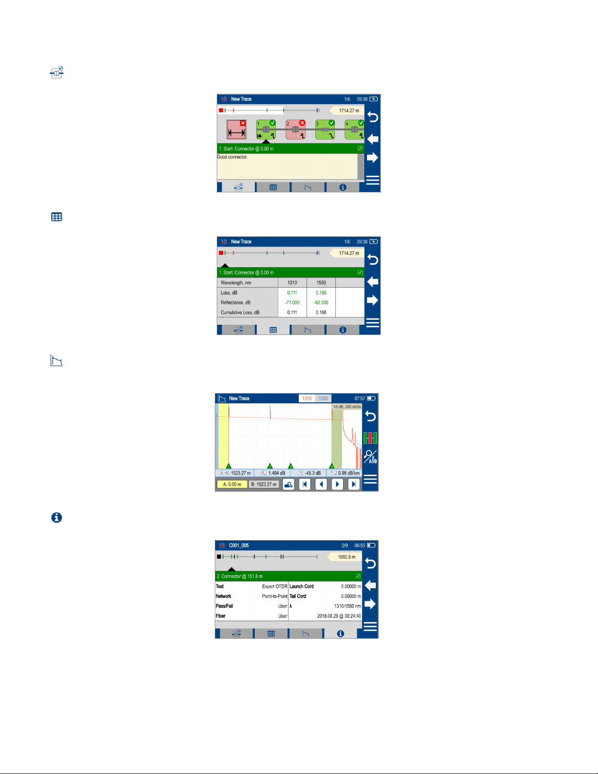
OTDR Test Results Viewers
In SmartAuto®OTDR and Expert OTDR test results may be displayed in four views. To display each view touch the associated tab.
1. LinkMap View - displays an icon-based representation of the network.
2. Event Table View - displays measurements for the currently selected Link Summary, Event, or Section.
3. Trace View - Displays OTDR trace(s), graph scale (dB/div & m/div), A/B cursor locations, A-to-B cursor distance, loss, reectance and loss/distance
measurements.
4. Test Info View - displays summary of OTDR settings used for this test.
In Real-time OTDR test results are displayed in Trace View only.
14
SmartAuto®OTDR
SmartAuto OTDR Setup Summary
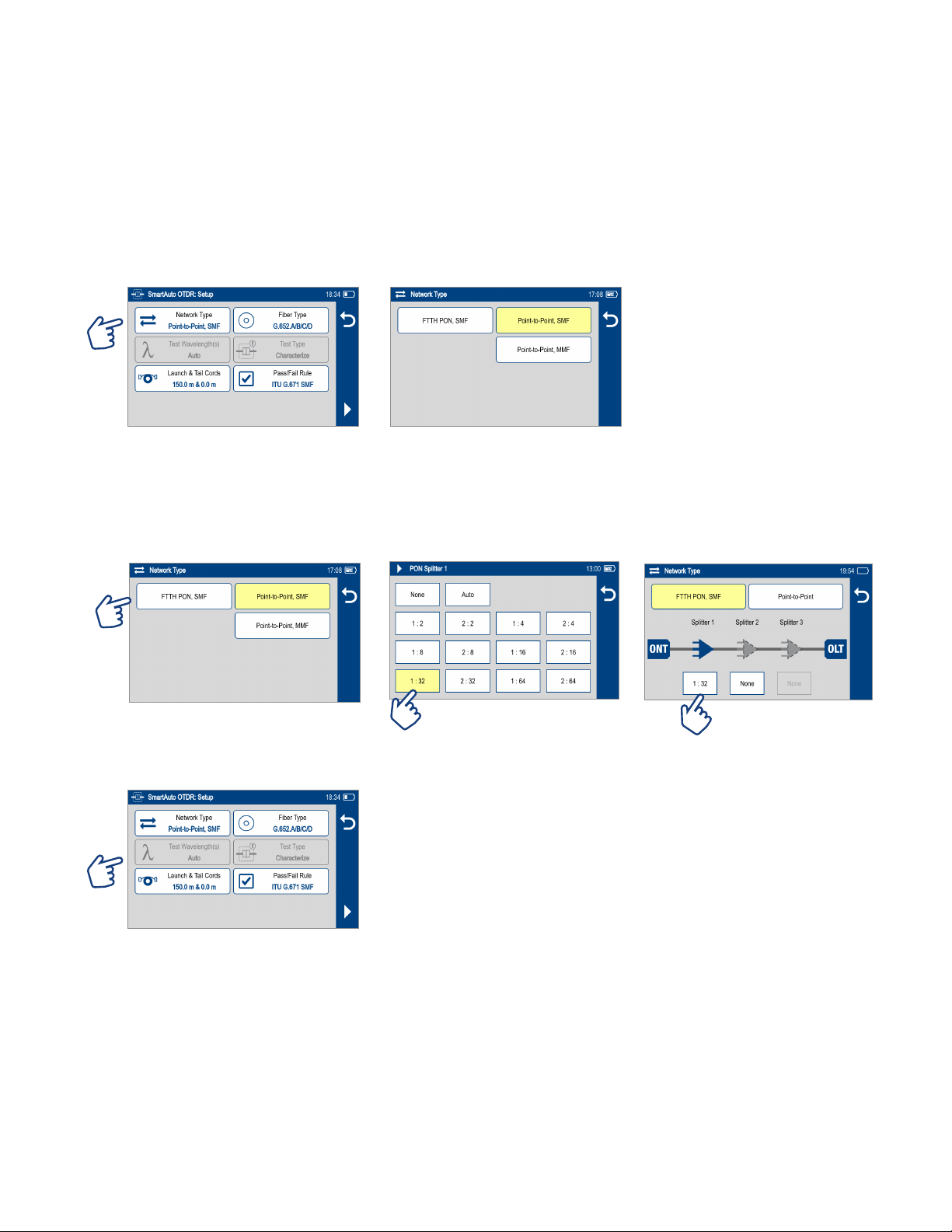
Network Type
Congure Network Type:
• Touch Network Type Select the network type:
–FTTH PON, Single-mode
–Point-to-Point, Single-mode
–Point-to-Point, Multimode
• Congure splitters if the FTTH PON option is selected. You may chose 'Auto -detect' option or select Split Ratio from the available options.
–Auto – Automatically detects splitters and reports split ratio based on loss.
–Note: Excess loss at splitter may result in incorrect split ratio being reported
–Select split ratio for each expected splitter. Up to 3 splitters may be congured.
Test Wavelength
Test Wavelength(s) option is disabled - SmartAuto always tests both SMF or MMF wavelengths

15
Fiber Type
Fiber Type settings depends on the selected Network Type option. Touch the Fiber Type eld to display one of the following:
• Multimode OMx or User-MMF options
• Single-mode G.65x or User-SMF options
Viewing and Configuring Fiber Type
G.65x Fiber Settings may be viewed but NOT changed.
OMx Fiber Settings may be viewed but NOT changed.
User Settings may be viewed and changed.
To view G.65x or OMx Fiber Settings
• While in the OTDR Setup screen, make sure G.65x/OMx ber type is displayed in the Fiber Type eld.
• If not, touch the Fiber Type eld to display the Fiber Type menu and touch the desired G.65x/OMx ber types to select.
• When back in the OTDR Setup screen, touch and hold the displayed G.65x/OMx ber type to open and view the default settings as follows:
–Group Index of Refraction (GIR)
–Backscatter Coefcient (BC)
–Fiber Attenuation (ACI; Loss-per-Distance)
• Touch Back to return to the OTDR Setup screen.
To view and edit User Fiber Type Settings
• While in the OTDR Setup screen, make sure the User Fiber Type label is displayed in the Fiber Type eld.
• If not, touch the Fiber Type eld to display the Fiber Type menu and touch the User option to select.
• When back in the OTDR Setup screen, touch and hold the displayed User label to open the User Fiber Type settings screen and congure settings as follows:
–Group Index of Refraction (GIR)
–Backscatter Coefcient (BC)
–Fiber Attenuation (ACI; Loss-per-Distance)
• Touch the desired parameter eld (e.g. GIR @1310 nm) to display its Editor screen.
• Edit the value using on-screen controls. Touch Done to save changes and return to the User Fiber Type settings screen.
• Touch Back to return to the OTDR Setup screen.

16
Launch & Tail Cords
Touching Launch & Tail Cords option displays the Launch & Tail Cords Setup screen that allows the user to congure the following settings:
• Enable Launch Quality Check. When Launch Quality Check is enabled, FlexScan checks loss and reectance of FlexScan connection to the network enabling the
user to detect dirty, damaged, poorly seated, or mismatched (UPC to APC) connectors.
• Congure Launch and Tail Cords lengths, if present.
–Touch the Launch or Tail Cord eld to display the length editor screen.
–Using on-screen controls, enter the desired length.
–Touch Done to save changes and return to the OTDR Setup screen.
Pass/Fail Rule
Touch Pass/Fail Rule option to select ITU G.671, TIA-568.3-D or User-congured rules:
• ITU G.671 Pass/Fail Settings may be viewed but NOT changed.
• TIA-568.3-D Pass/Fail Settings may be viewed but NOT changed.
• User Pass/Fail Settings may be viewed and changed.
OTDR results are evaluated against selected or congured rules:
Pass/Fail Limit ITU-G.671 TIA-568.3-D
Pass if Splice Loss ≤ 0.3 dB ≤ 0.3 dB
Pass if Connector Loss ≤ 0.5 dB ≤ 0.75 dB
Pass if Conn. Reectance ≤ -35 dB (SM);
≤ -26 dB (MM)
≤ -35 dB (SM);
≤ -26 dB (MM)
Pass if Splitter Loss Min ≤ Loss ≤ Max (dB) (Split ratio dependent) Loss ≤ Max (dB) (Split ratio dependent)
Pass if Splitter Reectance ≤ -55 dB ≤ -55 dB

17
Viewing and Configuring Pass/Fail Rule
• ITU G.671 Pass/Fail Settings may be viewed but NOT changed.
• TIA-568.3-D Pass/Fail Settings may be viewed but NOT changed.
• User Pass/Fail Settings may be viewed and changed.
To view ITU G.671 or TIA-568.3-D Pass/Fail Rule Settings:
While in the OTDR Setup screen, make sure the ITU G.671/TIA-568.3-D Rule is displayed in the Pass/Fail Rule eld.
• If not, touch the Pass/Fail Rule eld to display the Rules menu and touch the ITU G.671/TIA-568.3-D option to select.
• When back in the OTDR Setup screen, touch and hold the displayed Rule to open one of the settings screen:
–Splice & Fiber Section Limits screen
–Connector Pass/Fail limit screen
–One of three Splitter Pass/Fail Limit screens
• Touch Left / Right Arrows to cycle through Limits screens.
• View settings.
• Touch Back to return to the OTDR Setup screen.

18
To view and edit User Pass/Fail Rule Settings:
• While in the OTDR Setup screen, make sure the User Rule label is displayed in the Pass/Fail Rule eld. If not, touch the Pass/Fail Rule eld to display the Rules
menu and touch the User option to select.
• When back in the OTDR Setup screen, touch and hold the displayed User Rule to open one of the Pass/Fail Limits screens:
–Splice & Fiber Section Limits (screen 1 of 5)
–Connector Pass/Fail Limits (screen 2 of 5)
–Splitter Pass/Fail Limits screen Limits (screen 3, 4, 5 of 5)
–Touch Left / Right Arrows to cycle through screens.
–Touch the desired threshold eld to display its Editor screen.
–Edit the threshold value using on-screen controls.
–Touch Done to save changes and return to the Thresholds screen.
• Touch to return to the OTDR Setup screen.
To Start SmartAuto OTDR Test
1. Initiate the SmartAuto test by touching Start soft key or pressing Start/Stop button.
2. FlexScan begins testing with the Live Fiber check and if a live ber is NOT detected, proceeds to next step.
3. If the Launch Quality Check is enabled, FlexScan checks loss and reectance of the OTDR connection.
4. If launch quality is ‘Good', FlexScan starts testing at both wavelengths using SmartAuto settings.
5. When testing is completed, FlexScan displays the LinkMap®screen, which is a primary display in SmartAuto OTDR mode.

19
Understanding LinkMap®View Features
LinkMap is an icon-based representation of the analyzed network.
1. File name: consists of cable name and ber number, or “New Trace” if le has not been saved.
2. x/y or x1-x2/y, where
• x = number of the selected event
• x1-x2 = link section between events x1 and x2
• y = total events
3. Time of Test as congured in General Settings.
4. Battery icon indicates battery state.
5. Back key: touch to return to the previous menu.
6. Left/Right arrow keys: touch to move to next or previous event or link section.
7. Menu key: touch to navigate to Save As screen.
8. Link map thumbnail view with proportionally spaced events.
9. Link Length.
10. LinkMap detail view: shows summary and rst 4 events, or up to 5 events. White highlighted area in thumbnail view indicates region of ber for which events
are shown in the detail view.
11. Link Summary icon: may be green (all events passed) or red (one or more events failed).
12. Event icon: event icons may be green (pass) or red (fail). Pass/Fail fault is based on event loss and reectance thresholds congured by the currently selected
Pass/Fail Rule.
13. Fiber Section between events.
14. Selection marker indicates selected Summary, Event or Fiber Section for which additional details are displayed.
15. Details of the currently selected Summary, Event, or Section.
16. LinkMap tab: when in any other test results viewer (Event Table, Trace View, Test Info View), touch to return to LinkMap View.
17. Event Table tab: touch to display measurements for the currently selected Link Summary, Event, or Section.
18. Trace tab: touch to display Trace view that depends on active icon (Link Summary, Event, Section):
–If Summary icon is active, trace of entire network will be displayed
–If Event icon is active, trace zoomed in at event will be displayed
19. Info tab: touch to display summary of OTDR settings used for this test.
123 4
8
5
9
10
6
7
11 12
14
15
16 17 18 19
13

20
Understanding Event Table View Features
Event Table View may be accessed from either LinkMap®or Test Info View by touching the Event Table tab
Event Table View displays measurements for the currently selected Link Summary, Event, or Section.
• Touch the desired Event icon (or Section) to learn more details about that Event (or Section)
–Swipe or touch Left / Right Arrows to move to previous or next ber Section or Event.
• Touch Event Table tab to view selected Summary, Event, or Section details.
Other manuals for FlexScan FS300
2
Table of contents
Other AFL Diagnostic Equipment manuals


