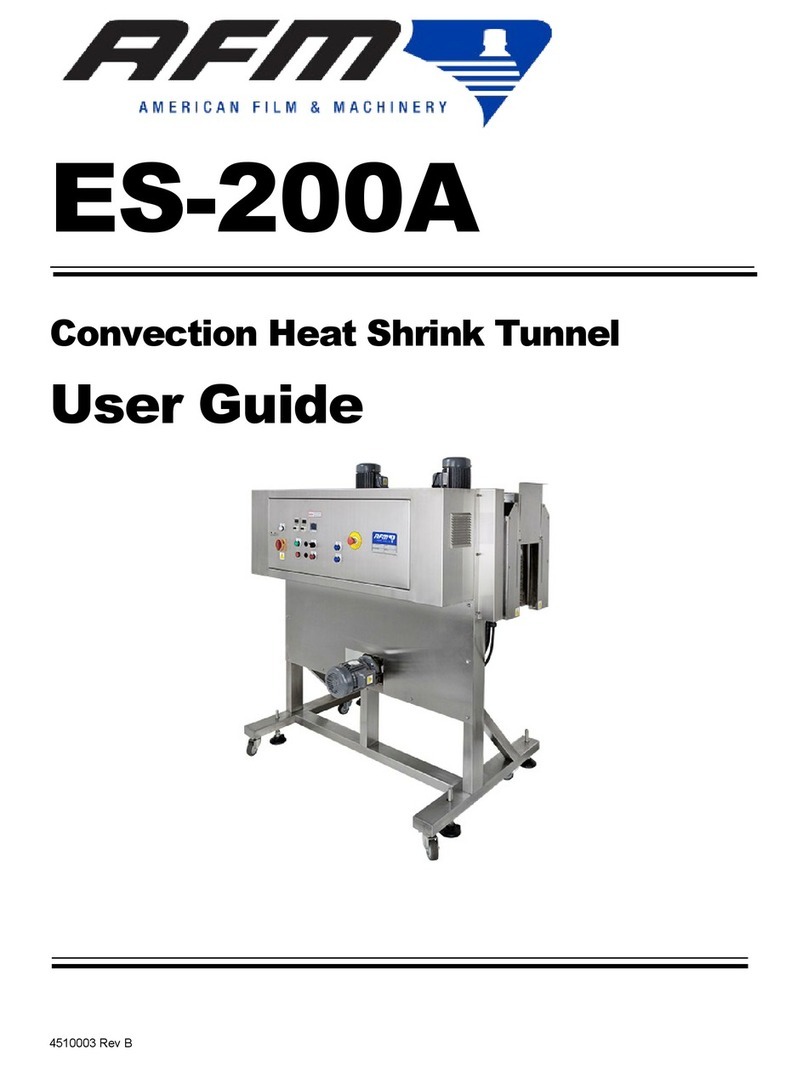
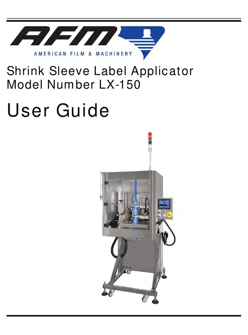
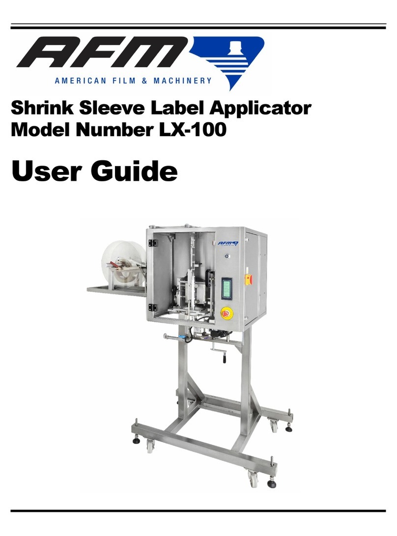
AFM GS 75 User manual

GS 75 & 100
Radial Heat Shrink Tunnel
User Guide


GS 75 & 100
Radial Heat Shrink Tunnel
Model
User Guide
Revised 11/8/2018
P/N 4510008 Rev A
Copyright and Trademarks
Copyright ©2018 American Film and Manufacturing.
All rights reserved. All trademarks and brand names
are the property of their respective owners.
AFM
7041 Boone Avenue North
Brooklyn Park, MN 55428
Phone: (714) 974-9008; Fax (763) 795-8867
www.afmsleeves.com


Contents:
Safety.........................................................................................................6
WARNINGS
................................................................................................................. 7
Safety Notes:................................................................................................................. 8
Introduction ...............................................................................................9
General System Description ......................................................................................... 9
System Components..................................................................................................... 9
System Specifications ................................................................................................. 10
Options........................................................................................................................ 11
Installation and Setup.............................................................................12
General Recommendations ........................................................................................ 12
Unpacking and Placement .......................................................................................... 13
Check for shipping damage.................................................................................................13
Mounting ..................................................................................................................... 14
Electrical Connection .................................................................................................. 16
Sleever Placement ..............................................................................................................17
Control Cabinet Overview ........................................................................................... 18
Operation .................................................................................................19
Power Up .................................................................................................................... 19
Shutdown .................................................................................................................... 22
Part Replacement....................................................................................23
Electrical box parts..............................................................................................................23
Replacing Sheaf Heaters ....................................................................................................24
Replacing Fan Assembly.....................................................................................................30
Troubleshooting ..................................................................................................................32
Maintenance ............................................................................................33
Mounting Hardware and Connections .................................................................................33
Cleaning External................................................................................................................33
Schematics..............................................................................................34
Wiring Diagram ...................................................................................................................34
Exploded Diagram...............................................................................................................35
Exploded Diagram Fan........................................................................................................36
Inside of Power Box ............................................................................................................37
Parts List .................................................................................................38
Recommended Replacement Parts.....................................................................................39
Component Dimensions ..........................................................................40
Warranty Statement ................................................................................41
Warranty Verification ...........................................................................................................42
Limited Warranty .................................................................................................................43
Customer Support ...................................................................................44

6Safety
Safety
The GS Heat Shrink Tunnel is easy to install, operate and maintain. Please follow these
safety steps to insure smooth and safe operation:
All operators should study this manual thoroughly before operating the machine.
•Always follow GMP (Good Manufacturing Practices) when operating this machinery.
•The machine is heavy. While unpacking and setting up the unit, always take care to
use proper lifting techniques. Avoid over-reaching and leaning over while handling the
machine and accessories. Use more than one person to lift and move the tunnel.
•Wear safety shoes and work gloves when moving the machine.
•Beware of uneven spots on the factory floor when moving the unit.
•Make sure the electrical power source is properly wired and grounded. The power
source should comply with all safety regulations and codes applicable to the
installation location.
•Before attempting any service or repair, make sure that the power is turned off and
power cable is disconnected from the power source.
•Before connecting the air supply, make sure that the pressure gauge is closed and
that the pressure indicator reads zero.
•The equipment generates heat, so make sure the area is properly ventilated.
•Do not place any body parts or tools into a running machine!
•Turn off and unplug the machine while servicing and performing maintenance
procedures.
CAUTION
TEAM LIFT

7 Safety
WARNINGS
Every effort has been taken to insure safety while operating this machine, however,
there are certain risks remaining. Do not allow this machine to be
operated before
informing all personnel of the attached warnings:
•
Do not tamper with electrical wiring. Use only licensed electricians for
maintenance. Always disconnect electrical power before attempting
maintenance to any electrical or moving parts.
•
To prevent injury to machinery and/or personnel, DO NOT INCREASE
SETTINGS ON EITHER ELECTRICAL OR MECHANICAL OVERLOAD
SAFETY DEVICES.
•
KEEP HANDS AWAY FROM MOVING CONVEYORS AND ASSEMBLIES.
Conveyor belts that have become worn or frayed can be hazardous and should
be replaced promptly.
•
NEVER OPERATE THIS OR ANY MOVING EQUIPMENT WITHOUT ALL
COVERS
AND GUARDS IN PLACE. The internal mechanism of most
packaging machinery contains numerous
shear, pinch, and in-running nip
points, many of which are capable of causing severe injury and permanent
disfiguration.
•
To minimize potential for personal injury, always be sure that machine
operators and others working on machinery are properly
trained in the
correct usage of the equipment and properly instructed
regarding the safety
procedures for operation.
•
DO NOT MAKE ANY MODIFICATIONS TO EITHER THE ELECTRICAL
CIRCUITRY OR THE MECHANICAL ASSEMBLIES OF THIS
MACHINERY. Such modifications may
introduce hazards that would not
otherwise be associated with this machinery. American Film & Machinery will not
be responsible for any consequence resulting from such unauthorized
modification.
•
The use of certain types of plastic films in sealing and/or shrinking equipment
may result in the
release of HAZARDOUS FUMES due to the degradation of
the film at high temperatures. Before using
any plastic film in this equipment,
the manufacturer or supplier of the film should be contacted for specific
information concerning the potential release of hazardous fumes. ADEQUATE
VENTILATION
SHOULD BE PROVIDED AT ALL TIMES.
•
Keep combustible and explosive materials away from this equipment. The
equipment may be a source of ignition.

8Safety
•
Do not use with pressurized containers. Exposure to high temperatures can
cause pressurized containers to burst, and could cause injury to operators
and other personnel nearby.
•
Take care when clearing product jams inside the heat tunnel. Do not use
anything that could potentially puncture a container. Use the hand crank to
raise the tunnel from the conveyor before clearing product from inside the
heat tunnel. If containers remain in the heat chamber, turn off power and
allow the temperature to drop below 100
F
before clearing. Temperature
inside the tunnel can easily cause burns.
Safety Notes:
Electrical Hazard-do not open cover. No user-serviceable parts inside.
Ensure that unit is properly grounded.
Fumes may be harmful to the environment.
Do not tamper with electrical equipment.
Keep the equipment dry and indoors.
Some fumes may be a health hazard if exposed to for too long.
Insure the area has adequate ventilation.

Introduction 9
Introduction
General System Description
The intended use of AFM heat shrink tunnels, is for the shrinking of heat shrink
film (labels, tamper bands, multi-pack), on containers over which they have been
applied. Containers with labels are to enter the tunnel, on a conveyor, for a
duration of between a minimum of 3 seconds, to a maximum of 6 seconds. This
dwell time of 3-6 seconds is necessary to achieve proper coverage without
overheating the containers. Operators must make sure that every container that
enters the AFM tunnel exits within this maximum time of 6 seconds.
AFM shrink tunnels are intended for industrial use only.
System Components
•Stainless Steel Brackets with Height Control
•IR Heat Tunnel
•Operator Controls
2207
Tunnel
External
Cover
Controls
Blower Motor
Wiring Enclosure
Mounting
Rod

10 Introduction
System Specifications
Power: A.C. 1-Phase, 220 Volt, 50/60Hz
Machine Dimensions : 75-185mm W (7.28”) x 565mm L (22.24”) x 530mm H (20.86”)
100-185mm W (7.28”) x 565mm L (22.24”) x 530mm H (20.86”)
Tunnel Dimensions : 75mm W (2.95”) x 565mm L (22.24”) x 95mm H (3.75”)
100mm W (3.94”) x 565mm L (22.24”) x 95mm H (5.90”)
Temperature: 250C
Heater: 2.5KW x 2

Introduction 11
Options
Conveyor Conveyor is supplied by customer. For conveyor
options, please consider an AFM conveyor system.
Accumulator Accumulator is supplied by customer. For Accumulator
options, please consider an Eastey Accumulator
system.
Feed Screw Feed Screw is supplied by customer. For Feed Screw
options, please call the AFM Customer Service
department for details.
Unwind Unwind is supplied by customer. For Unwind options,
please call the AFM Customer Service department for
details
Sleever Sleever is supplied by customer. For Sleever options,
please consider one of our many quality AFM Sleever
systems.
Brushdown Brushdown unit is supplied by customer. For
Brushdown options, please call the AFM Customer
Service department for details.
Tamp down Tamp down unit is supplied by customer. For Tamp
down options, please call the AFM Customer Service
department for details.
External Controls Call the AFM Customer Service department for details.
For any Sales-related questions, please call us at 763-398-1743.
We would be happy to assist in any way possible!

12 Installation and Setup
Installation and Setup
General Recommendations
Material Handling
The most critical item for consistently achieving superior quality shrink applicating is
material handling. This is an area controlled by the customer and the installer. It is
imperative that adequate conveyor product guides be provided, and that they are installed
and maintained properly. Incorrect or inconsistent product handling will cause quality
problems, maintenance issues, and could lead to product damage. The customer is
responsible for maintaining proper material handling equipment.
Work Area
The GS may require cleaning from time-to-time due to environmental contaminants.
Maintenance Access
When planning the installation, allow for easy access to the tunnel so that cleanup can
be done conveniently.
Important! Turn off power and allow tunnel to cool before doing any
cleaning/maintenance.

Installation and Setup 13
Unpacking and Placement
Open the box and lift out the tunnel assembly by its cage. BE CAREFUL-UNIT IS HEAVY.
Attention! Use only the supplied mounting hardware to attach the
tunnel to the Bracket assembly. Using hardware other
than that supplied by AFM can result in damage to the
assembly.
Check for shipping damage

14 Installation and Setup
Mounting
After unpacking the Bracket Assembly, assemble it per the illustration, if required.
Find a spot to mount to Conveyor approximately 1” down from top of Conveyor.
Measure the distance to the Sleever (if used), and drill though one side of Conveyor.
Mount the Bracket to the Conveyor using the enclosed ¼-20 hex bolts. Tighten bolts and
nuts until snug. Fender washers may be used.
2208
Mount this angle to
Conveyor
approximately. 1”
lower than top of
Conveyor,
depending on
container size
Mounting
slots
2209

Installation and Setup 15
After Bracket has been mounted and tightened, use two (2) people to lift and attach the
Tunnel to the Bracket. Aim the two Mounting Rods on the Tunnel Assembly toward the
Mounting Collars on the Bracket. Slide Tunnel into the Collars.
Center the Tunnel parallel to the Conveyor and tighten the collars with an Allen wrench.
Collars (2)
2210
Rods (2)
2212

16 Installation and Setup
Electrical Connection
There is a power cord connected to the GS Tunnel. Plug this into a clean 220Volt AC
power source. DO NOT HOT-PLUG. Ensure that Tunnel has all switches turned to
“OFF” before plugging into any power source.
Place the correct male AC plug onto the end of the power wire. Check the connections,
and plug the male cord end into AC power.
2213
Power

Installation and Setup 17
Sleever Placement
Line up the Sleever to the existing Tunnel (if applicable). Insure that all controls on the
unit are easily accessible. Hook up the ventilation equipment, if required (It is a good
idea to have the exhaust ports vented outside of the building).
If not using a Sleever, make sure that the operator has enough room to move and is not
in danger of getting caught in moving mechanisms. Ensure availability of a trip cord or
other safety shutoff mechanisms.
2217
Sleever
2218

18 Operation
Control Cabinet Overview
Important! The control cabinet is not a watertight enclosure- do not
splash the cabinet with liquid.
The front face of the Control Cabinet has the following:
1. Power
2. “HEATER” switch
3. “FAN” switch
4. Left-and-Right Temperature Controls.
2224
Temperature
Controls
Heat
Power
Fan

Operation 19
Operation
Power Up
When all the components have been properly mounted and connected, the GS tunnel is
ready to power up and begin production.
Tip! Before powering up, double-check your installation. Make
a quick inspection to ensure all the components have been
securely mounted and all data and power cables are
properly seated and connected.
To power up the GS Tunnel, plug into power outlet. Push the power switch located on the
front of the controller to the ON (I) position.
Power Switch
2219
Airflow Control

20 Operation
Turn on FAN Switch
Turn on HEATER Switch
2224
Fan
Switch
Heater Switch
This manual suits for next models
1
Table of contents
Other AFM Industrial Equipment manuals
Popular Industrial Equipment manuals by other brands

Loepfe
Loepfe YARNMASTER 1N1 instruction manual
Eaton
Eaton Airflex WCBD Series Installation, operation and maintenance manual
Stober
Stober K38-03 operating manual

bon
bon E-30 instruction manual
Georg Fischer
Georg Fischer MULTI/JOINT 3000 Plus user manual
Panduit
Panduit FiberRunner QuikLock FR12X4 installation instructions
