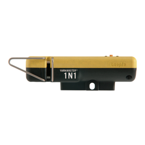
Loepfe YARNMASTER 1N1 User manual

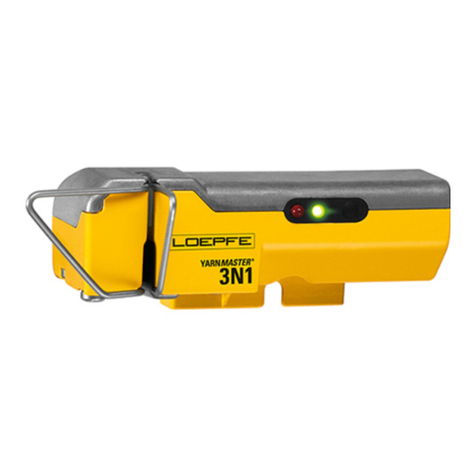
YARNMASTER ®1N1 / 3N1
46360003 en
Instruction Manual
Savio


Loepfe Brothers Ltd.
Kastellstrasse 10
P. O. Box 582
8623 Wetzikon / Switzerland
Phone +41 43 488 11 11
Fax +41 43 488 11 00
E-Mail service@loepfe.com
Internet www.loepfe.com
YarnMaster®is a registered trademark of LOEPFE Brothers
Ltd. for Switzerland and other countries.
All further company and product names are trading names or
registered trademarks of the relative companies.
The content of this Operating Instruction is protected by cop-
yright. All rights reserved. No part of this may be reproduced
in whatever form (by printing, photocopying, microfilm or oth-
er) without a written grant of LOEPFE Brothers Ltd., nor may
it be processed or distributed by any electronic mean.
Copyright©2012 LOEPFE Brothers Ltd., Switzerland
08. 2013 / Version 1.0.0

43N1
INHALTSVERZEICHNIS

TABLE OF CONTENTS
Table of Contents
General Information 7
Norms and Regulations 7
Instruction Manual 7
Liability 7
Safety Information 8
Warnings 8
General Safety Instructions 9
Yarn Clearing (General) 11
Definition of Yarn Faults 11
Yarn Fault Classification 13
Yarn Clearing 14
Foreign Matter (F) 15
Synthetic Foreign Matter (P) 15
Imperfections 15
Yarn Irregularities 15
Moiré 15
YarnMaster 1N1 / 3N1 16
Functional Range 16
Operating 17
Central Unit SCU 17
User Interface 17
Machine Overview 19
User Password 19
Data Entry 19
Settings Clearer Parameter / Start 20
Yarn Quality (Q) – 1N1/ 3N1 20
Lock Functions – 1N1 / 3N1 20
Foreign Matter (F) – only 3N1 21
Polypropylene (P) – only 3N1 21
Production, Lot Change 22
Light Tree 22
Styles 23

TABLE OF CONTENTS
Machine Data 24
Status > Overview 24
Status > Clearer Data 25
Q-Pack 27
Hitlist 28
Exceptions 29
Reports 30
Base Setup 31
User Interface 31
System 31
Shifts 31
Checks and Maintenance 32
USB 32
Q-Sensor LED 34
Cleaning 35
Index Data Explanation 35
Spare Part Numbers 36
Replacements of Sensor and SE-Board 36
Diagnostics 36
Service 39
Machine Configuration 39
Versions 39
Snapshot 39
Technical Data (Changes reserved) 40
Parameter Settings 41

73N1
GENERAL INFORMATION
Norms and Regulations
The LOEPFE YarnMaster®1N1 / 3N1 yarn clearing system
is a product which has been inspected for technical safety.
It complies with the following directives:
2006 / 42 / EC Machinery Directive
2006 / 95 / EC Low Voltage Directive
2004 / 108 / EC Electromagnetic Compatibility
Instruction Manual
To prevent faults and operating errors, we recommend to
carefully read this Instruction Manual and to carefully follow
the instructions given.
The screen representations in this manual
serve as illustration only. They should not be
used as setting examples!
A copy of this Instruction Manual must be kept easily acces-
sible near the machine.
Liability
The manufacturer assumes no liability for damage caused by:
Noncompliance with the safety, operating and mainte-
nance instructions contained in this Manual.
The use of spare parts / non-OEM parts / conversion parts
not supplied by us.
Unauthorized conversion and modification of the yarn
clearer.
Normal wear.
General Information

83N1
SAFETY INFORMATION
Warnings
In these instruction, safety information is marked with
symbols and signal words which point out the extent of
the hazard.
The safety information has to be strictly observed to prevent
accidents, personal injuries and damage to property.
Symbols
General hazard
Electrical hazard
Burn hazard
Flammable
Electrostatic-sensitive device
Property damage
Signal Words
Indicates an imminently hazardous situation
which will result in death or serious injury.
Indicates a potentially hazardous situation
which could result in death or serious injury
Indicates a potentially hazardous situation
which may result in minor or moderate injury
Indicates a potentially hazardous situation
which may result in damage to property.
Tips and Hints
Useful tips and recommendations
Safety Information
DANGER
WARNING
CAUTION
NOTICE

93N1
GENERAL SAFETY INSTRUCTIONS
General Safety Instructions
Risk of fatal injury from electric current!
Only perform maintenance work on electric components
when these are switched off, disconnected from the mains
and potential-free.
DANGER
Risk of contamination, overheating, spark interfer-
ence, fire!
This yarn clearing installation must only be operated
with the covers closed.
CAUTION
NOTICE:
Do not open any sensing head.
Improper operation of the equipment could cause
hazards!
This yarn clearing equipment must only be installed,
commissioned and operated by authorized and trained
personnel.
CAUTION
Electronic components and assemblies (printed cir-
cuit boards) are endangered by electrostatic charges!
Beware of touching the soldered connectors, pin contacts,
printed circuits or electronic components before they have
been discharged statically. Hold the units at the periphery
only.
NOTICE

113N1
YARN CLEARING GENERAL
Yarn Clearing (General)
Definition of Yarn Faults
The Open End spinning process supplies a relatively uniform
yarn. However, differences in yarn diameter cannot be com-
pletely avoided. Thus, it is first necessary to distinguish be-
tween normal yarn irregularities and actual yarn faults.
Yarn faults may be defined as yarn irregularities which can
lead to difficulties in subsequent production stages or to
faults in the end product. Yarn clearing is defined as the de-
tection and elimination of yarn faults. This task is performed
during the spinning process. Yarn clearer are, therefore, part
of a Open End spinning machine.
To eliminate a fault it is necessary to interrupt the spinning
process. The rotor must be stopped, the defect removed
from the package and a new piecing cycle must be initiated.
Obviously this interruption results in a loss of production. Yarn
clearing is, therefore, always a compromise between quality
and production, i.e. between the maximum possible number
of yarn faults which could be removed and the least accept-
able production loss. This compromise results in a distinction
between:
Acceptable yarn faults, namely those which are tolera-
ted for sake of machine efficiency, and
Unacceptable yarn faults (faults that cannot be toler-
ated)
Yarn Faults
Based on the average yarn diameter (basic diameter), the fol-
lowing yarn faults can be detected and cleared:
Thick and thin places are defined, depending on whether
there is an increase or a decrease in diameter.
Within the thick places further distinctions are made:
– Neps, as extremely short (up to a few mm) and extremely
thick faults (several times the base diameter)
Faulty piecing
Within the count deviation further distinctions are made
Thin and thick sliver (short length)
Thin and thick count (long length)
Neps
Short Faults
Long Faults
Thin Places
Piecing
Yarn Count (long)
Sliver (short)

12 3N1
YARN CLEARING GENERAL
Accumulations of Faults (Moiré)
Periodic defects (moiré)
Periodic defect where the period is related to the rotor diam-
eter of the OE rotor. They can be caused by contaminated or
used rotor
Other periodic defects
They can be caused by defects or wear from components of
the spinbox. These defects are detected by the spectrogram
analysis.
Yarn Irregularities (CV)
Disturbing diameter variations or sporadic irregularities, for
example:
Variation of yarn (CVy)
Variation of hairiness (CVh)
Variation of sliver (CVs)
Imperfections (IPI)
Foreign Matter (F)
Foreign matter with a color that is different from the base
color of the yarn:
Dark foreign matter in the raw yarn
Synthetic Foreign Matter (P)
Synthetic foreign matter (e.g. polypropylene)
Irrespective of the color of the yarn and the foreign mat-
ter, for example, white and transparent polypropylene in
raw-white yarn
Periodic
Irregularity
Hairiness
Sliver
Imperfections
In raw-white yarn
Synthetic foreign matter in raw-white yarn
Other periodic
defects

133N1
YARN CLEARING GENERAL
Figure 1
Diameter Y
Length X
Diameter
Figure 2
Length
Figure 3
Yarn Fault Classification
Yarn faults are defined in terms of a transverse dimension
and a longitudinal dimension. The transverse dimension is ex-
pressed as a deviation of normal diameter and the longitudi-
nal dimension in millimeters.
The definition of yarn faults in terms of length and thickness
suggests the representation of yarn faults in a Cartesian sys-
tem of coordinates. Thereby the length is plotted in the hori-
zontal direction (X-axis), and the thickness in the vertical di-
rection (Y-axis). Each yarn fault can, thus, be plotted as a
point in the plane of the coordinates. Furthermore, the plane
of the coordinates can be divided into individual fields (class-
es) in order to summarize (classify) similar yarn irregularities
into groups and to count them. This takes into account anoth-
er extremely important point of view, namely the frequency
of similar faults (see figure 1).
The choice of the class limits is largely random. Diameter
faults are most frequently divided into different thickness and
length classes (see figure 2).
The YarnMaster System 3N1 uses the following default clas-
sification (see figure 3).
Frequency distribution of yarn faults in the coordinate grid

14 3N1
YARN CLEARING GENERAL
Diameter
Length
Figure 4
Yarn Clearing
Base Curve
The distinction between yarn faults which are to be cut out
and those which are to be left in the yarn (unacceptable and
acceptable yarn faults), which is made in the interest of Open
End spinning efficiency, has already been pointed out. This
distinction can be represented graphically on the plane of
coordinates as a line which separates the acceptable faults
(below) from the unacceptable ones (above). This line repre-
sents the theoretically-desirable base curve (RG). A con-
cave base curve (see figure 4) normally corresponds to the
requirements in practice.
The concave shape arises from the textile evaluation, where-
by the greater the deviation in diameter that is tolerated, the
smaller the length deviation that appears acceptable. Fur-
thermore, the base curve, thus, passes through fields of simi-
lar fault frequencies, which meets the requirement of high
efficiency.
A distinction must be made between the theoretically-desir-
able base curve and the practically-achievable quality set-
tings, which depends on the one hand on the clearing cha-
racteristic typical of a clearer type, and, on the other hand, on
its setting flexibility.
Clearer Characteristics
Matrix Clearing
Each time the detector sees a single diameter measurement
that deviates for more than +25% or -20% from the reference
mean value (this is the noise region of normal yarn irregular-
ity!), this measurement is considered as the possible begin-
ning of a yarn defect. Subsequent diameter samples are kept
in memory until the yarn diameter is again between the noise
region around the reference mean. At this time, the average
defect diameter deviation and the defect length are calculat-
ed. One defect is then added to the count in the appropriate
field of the 8x8 matrix, first column is not shown (contains
NEPS). This classification matrix divides all defects into 8 di-
ameter classes (2 for thin places; 6 for thick places) and 7
length classes The class limits can be set freely by the user.
Piecings
Clearing according to the settings of the quality matrix allows
for the creation of a optional piecing defect detection (de-
pending on type of machine).
RG

15
YARN CLEARING GENERAL
Foreign Matter (F)
The human eye is determining color differences by detecting
differences in light absorption. The sensor for foreign matter
incorporated in 3N1 is measuring these differences in light
absorption to detect foreign matters in the yarn in a most ef-
fective way. Foreign matters are classified in a 7 x 8 matrix.
Synthetic Foreign Matter (P)
The detection of synthetic foreign matter as polypropylene,
polyamide (nylon) etc. is based on triboelectricity. The dif-
ferent electrical charging of materials (e.g. cotton and poly-
propylene) caused by travelling of the yarn over a detection
element. The settings and classification can be displayed in
a 7 x 8 matrix.
Triboelectric Effect
The triboelectric effect is an electrical phenomenon where certain
materials become electrically charged after coming into contact with
another different material. The polarity and strength of the charges
produced differ according to material and surface smoothness. That
means: The further the materials lie off each other in the series, the
more definitely they can be detected.
Imperfections
Frequent yarn faults are described as Imperfections in the
language of the textile industry. It is generally acknowledged
that the shorter the fault length, or the smaller the diameter
deviation respectively, the more frequent the event.
The source of these faults is found in the raw material or in a
non-perfect spinning process. The raw material, card wires,
opening rollers, rotor, navel have a significant influence on the
imperfections.
With a reliable analysis of the Imperfections it is not only pos-
sible to optimize the production process but also conclusions
can be drawn concerning the quality of the used fibre material.
Yarn Irregularities
The monitoring and evaluation of the surface structure of a
yarn (e.g. hairiness), is a further important criterion for quality
assurance. In order to predict yarn behavior during processing
in weaving or knitting, it is not sufficient to simply consider in-
dividual quality characteristics (e.g. yarn irregularity) to assess
a yarn. Only a combination of different quality criteria (e.g. hair-
iness and irregularity) supports making a definite conclusion.
Moiré
Moiré is a repetitive yarn defect caused by point contamina-
tion of the rotor’s internal groove. Such contamination of the
rotor produces thick places in the yarn with a distance to each
other equal the rotor circumference.
MASTERS IN TEXTILE QUALITY CONTROL
TRIBOELECTRIC SERIES
Dry Human Hands, Skin
Leather
Rabbit Fur
Glass
Human Hair
Nylon (Polyamid)
Wool
Fur
Lead
Silk
Aluminium
Paper
Cotton
Steel
Wood
Amber
Hard Rubber
Nickel, Copper
Brass, Silver
Gold, Platinum
Polyester
Saran Wrap
Polyacrylic
Polyurethane
Polyethylene (scotch tape)
Polypropylene
Acquires a more
positive charge
+
+
-
–
Acquires a more
negative charge
Triboelectric Series
Hairiness
Moiré
Imperfections
Irregularity

16 3N1
FUNCTIONAL RANGE
YarnMaster 1N1 / 3N1
Functional Range
P Clearing
– Clearing of synthetic foreign
matter PP PE etc.
– Matrix setting and classification
– P cluster clearing
F Clearing
– Clearing of foreign matter
– Matrix setting and classification
– Foreign matter cluster clearing
Quality
– Clearing
N Neps
S Short Faults
L Long faults
T Thin places
– Yarn count channel
Thin and thick count
– Sliver channel
Thin and thick sliver
– Moiré
– Piecer clearing
(depends on machine type)
– Yarn irregularities CV%
– Imperfections (IPI)
– Classification of faults
– Online laboratory Graphics (Q-Pack)
Variation of yarn (CVy)
Variation of hairiness (CVh)
Variation of sliver (CVs)
YARNMASTER
1N1
YARNMASTER
3N1

173N1
OPERATING
Operating
Central Unit SCU
ATouch Screen
The central unit is operated by direct inputs on the touch
screen. Applying light pressure on the screen surface acti-
vates the functions shown.
Tap the menu item to be selected with the finger
Do not use a pointed, metallic object as this could damage
the monitor surface!
Cleaning:
The monitor surface is made of plastic material. Clean the
monitor with a soft cloth. Heavy soiling can be cleaned with a
cloth moistened with a water and soap solution.
BUSB Port
USB port to transfer reports and clearer data to a server and
printer. The USB port is protected against dust and humidity
by a removable cover.
A
B
User Interface
1Menu Bar (Overview Tabs)
Tapping the tabs in the header calls up the respective
menus.
Machine Data: Shows all important data
Setup: Used for all kind of settings
Service: Used partly for one-time base set-
tings and for service applications
2Overview Page
Shows all data on a selected page. Depending on
the page displayed, the settings can be entered or an
overview of the data is possible.
3Navigation Bar
Navigation buttons:
Enter a rotor number to display the rotors’ related data.
1
2
3
Important short names for the manual, used in the manual
Q = Quality SCU = Sensor control unit
F = Foreign matter SE = Section electronic
P = Polypropylene SH = Sensing head
UI = User interface

18 3N1
OPERATING
3Navigation
Pages can contain following buttons:
Next / previous page / list.
Select next / previous option / value.
Enter rotor number.
First / last rotor of the selected machine side.
First / last rotor of the selected section.
Previous /next rotor. Keep touched for fast scrolling.
Switch machine side.
Deselect rotor.
Refresh the shown data.
To remove this button from or to add it to each page: Setup > User Interface > General.
Change the user interface language.
To remove this button from or to add it to each page: Setup > User Interface > Languages.
Lock / unlock data entry with a password.
To remove this button from or to add it to each page: Setup > User Interface > Passwords.
Unlock technical alarm
Unlock hardware
Unlock rotor
Save a style setting with a style name to the SCU / load a style setting to a machine side
Save reports or styles to USB / load styles from USB to SCU
Snapshot of the SCU including all values: Service > Diagnostics
Warm restart
Cold restart / reboot the SCU
Touch the cleaning button before cleaning the touch screen.
To remove this button from or to add it to each page: Setup > User Interface > General.
Sort the list.
Scroll the list.
Replace the settings by the default settings. Touch to apply the default settings.
Undo changes.
Cancel the changes.
Save the entered data (all changes need to be confirmed).
Clear list / report.
Additional buttons are explained per page.
/
/
/
/
/
/
/
/
/

193N1
OPERATING
Machine Overview
The header contains:
Machine number
Date and time
Number of stopped rotors
Shift start date and time
The machine block shows you the state of each particular ro-
tor (see caption below).
Information about the total efficiency and production data on
both sides. For more information see chapter Machine Data /
Status / Overview.
Overview shows the data for the entire
machine or for one side.
Rotor Status Color Codes
The Rotor status color gives the information about the condi-
tion of each rotor.
User Password
Default: 123
Enter the password and confirm.
The Password can be changed individually: Setup > User Inter-
face > Passwords
Qualified personnel can touch the lock button and enter the
service password.
Change to capital letters and alternative characters with Cap
button.
Data Entry
Data entry needs to be confirmed twice, once in the data en-
try window and once in the corresponding main window. The
left side shows the selected parameter and the possible limit
range for the parameter.
The indicator in the machine block shows the selected rotor.
Color Status
Lime green Running
Grey No communication
Black Hardware locks, forced lock
Red Quality locks
Purple Foreign matter locks
Teal Polyprop locks
Orange Quality stops
Color Status
Fuchsia Foreign matter stops
Blue Polyprop stops
White Yarn broken
Green yellow Run + inhibit
Tan Dust stops
Brown Dust locks
Cyan Forced stop

SETTINGS CLEARER PARAMETER / START
Yarn Quality (Q) – 1N1 / 3N1
The yarn clearing to control the yarn structure gets activated
by setting classes within the clearer matrix. The length and
deviation limits of the classes can be set individually within
certain limits.
Thin and thick sliver for detection of misplaced cans or
partly decreasing / increasing of the sliver diameter
Moire: Length of the fault depending on rotor diameter
Neps sensitivity: length generally 5mm, deviation selectable
Piecer sensitivity deviation selectable (% of general clear-
ing during piecing)
Lock Functions – 1N1 / 3N1
The lock functions are used to block particular rotors that
have repetitive quality stops or longer defects which can not
be removed by the piecer.
All lock functions can be enabled or disabled by setting of a
tick in the box next to the lock function.
The blocked spindles need to be unlocked before the start
again. This can be done with the SCU, the button on the sens-
ing head, or the unlock cards.
The unlock card level can be set to three different levels. Each
level can be unlocked by the unlock card of the same level or
higher.
Settings Clearer Parameter / Start
Activate the different yarn clearer functions by ticking the box next to the specific clearer channels.
The major clearer channels can be set by the selection of classes of within the clearer matrix through the touch screen. Each
class is limited by a length and deviation limit which both can be set individually within certain limits.
A red class is activated for clearing, a yellow one can get selected in addition. The light yellow classes are disabled by the system.
The additional clearer channels can be set by entering a setting within the certain limits.
The range for all settings can be found in chapter Technical Data / Parameter Settings, but the range will also be shown on the SCU
when you change a setting.
Other manuals for YARNMASTER 1N1
1
This manual suits for next models
1
Table of contents
Other Loepfe Industrial Equipment manuals

Loepfe
Loepfe YARNMASTER 3N1 Install guide

Loepfe
Loepfe YARNMASTER ZENIT+ User manual

Loepfe
Loepfe YARNMASTER 3N1 Install guide

Loepfe
Loepfe YARNMASTER 1N1 User manual

Loepfe
Loepfe YARNMASTER 3N1 Install guide

Loepfe
Loepfe YarnMaster Zenit User manual

Loepfe
Loepfe YARNMASTER 3N1 Install guide

Loepfe
Loepfe YarnMaster PRISMA User manual