schmalenberger fluvo NT2 rondo User manual

GB
27211 - F.1
NT2 rondo
D
D
F
I
E

CONTENTS
2NT2 rondo
Version:27211 - F
Schmalenberger GmbH + Co. KG
D-72072 Tübingen / Germany
Contents
1General.................................................................................................3
2Safety Instructions..............................................................................3
3Unit Description / General Technical Data........................................5
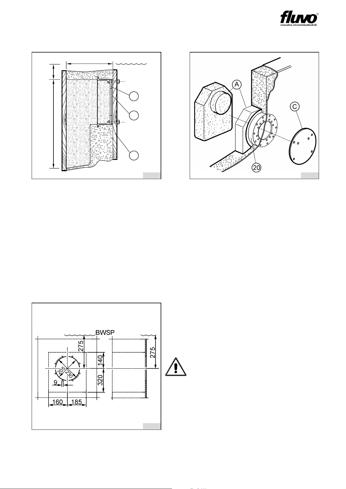
4Installation Site Specifications / Installation....................................8
4.1 Planning the pump pit .......................................................................................................8
4.2 Installation Preparations / Concrete pool ..........................................................................9
4.3 Installation Preparations / Pre-fabricated pool ..................................................................9
4.4 Installation Preparations / Wood-liner pool .......................................................................10
4.5 Pump kit Installation / Concrete-tile pool ..........................................................................10
4.6 Pump kit Installation / Concrete-liner pool ........................................................................11
4.7 Installation kit and Pump kit Installation / Pre-fabricated pool ..........................................11
4.8 Installation kit and Pump kit Installation / Wood-liner pool ................................................12
4.9 Non-return air valve Installation .......................................................................................13
4.10 Installation of the face plate assembly - general ...............................................................13
5Electrical Connections .......................................................................16
5.1 Electrical Connections - general........................................................................................16
5.2 Electrical connections three-phase current........................................................................17
5.3 Electrical connections AC..................................................................................................17
6Start-up / Operating ............................................................................18
7Shutdown / Overwintering..................................................................20
7.1 Empty the pool .................................................................................................................20
7.2 Face plate assembly overwintering ...................................................................................20
7.3 Emptying the pump ........................................................................................................20
8Maintenance / Repairs........................................................................21
8.1 General Instructions...........................................................................................................21
8.2 Maintenance / Service .......................................................................................................21
8.3 Repairs ..............................................................................................................................21
9Spare parts ..........................................................................................21
10 Spare parts list an drawing..............................................................22
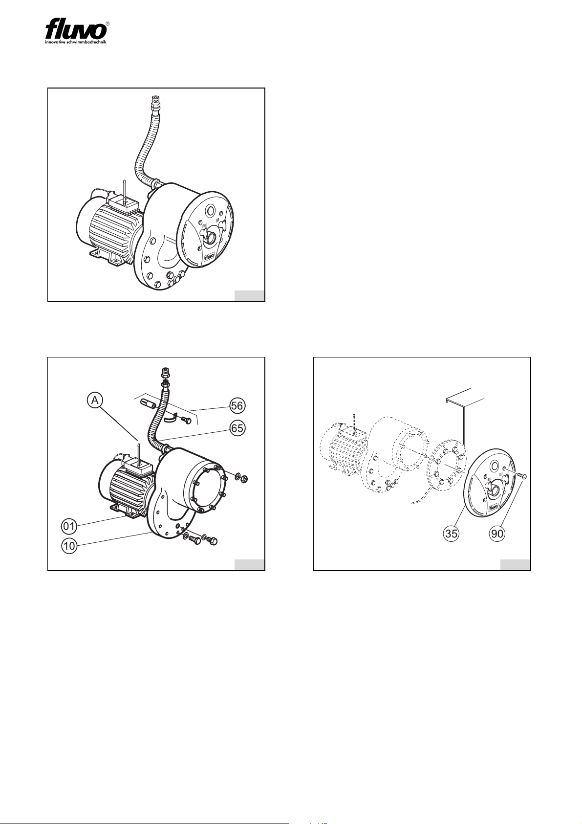
10.1 Spare parts list.................................................................................................................22
10.2 Drawing............................................................................................................................26

OPERATOR‘S MANUAL
3
NT2 rondo
Version: 27211 - F Schmalenberger GmbH + Co. KG
D-72072 Tübingen / Germany
1 General
1.1 Guarantee notice
If the instructions contained in this operator’s manual are not observed then any
claims under guarantee shall be void.
1.2 General
All parts coming into contact with media are designed for water quality to DIN 19643.
This counter-current swimming system is of state-of-the-art technology.
This manual does not take into account local regulations, the observance of which is the
responsibility of the operator – also on behalf of installation personnel that may be invol-
ved.
The type plate specifies the machine series, the frame size, the most important operating
data and the serial number. Please be sure to quote it in case you require more information
and also when placing subsequent orders or ordering spare parts.
1.3 Usage Instructions
The counter-current system was designed for use in private swimming pools. Consequent-
ly it must not be installed in public swimming pools. Neither the entire unit nor parts thereof
must be used in other systems. You are expressly directed to use it only in accordance with
these instructions.
The counter-current system must not be operated beyond the parameters stated in the
technical data (3.1) . In case of doubt, please contact your customer service or the manu-
facturer.
2 Safety Instructions
2.1 General
• Prior to starting up, make sure that the operators have read and understood the
operator’s manual. Not the operator but the owner is responsible for safety!
• Make sure that the relevant safety regulations and laws are observed in the operating
company and / or country where the counter-current systems are to be used.
• All parts that come into contact with the medium are resistant to an absolute salt con-
tent of up to 0.75% (4,500 mg/l Cl¯). If the salt concentrations are greater than this, the
manufacturer must be consulted.
• Use the counter-current system only if it is in perfect technical condition, in accordance
with the regulations, observing safety requirements and danger conditions and strictly
adhering to all the instructions in the operator’s manual!
• Promptly remedy any faults that could influence safety.
For more details of safety instructions please see the operator´s manual
WK (27220).

OPERATOR‘S MANUAL
4NT2 rondo
Version:27211 - F
Schmalenberger GmbH + Co. KG
D-72072 Tübingen / Germany
2.2 Symbols
In these operating instructions the following symbols are used to draw your special atten-
tion to dangers:
Notices attached directly to the counter-current system , e.g. the arrow indicating the direc-
tion of rotation, must always be observed and maintained in a clearly legible condition.
2.3 Safety Instructions for the Operator
1. Electrical equipment must be installed and maintained by qualified electricians. The ap-
propriate local safety requirements and installation regulations must be observed. The
expression “qualified person” is defined in VDE 0105 and IEC 364 There is no informa-
tion contained in this operator’s manual for unqualified persons. It must be pointed out
that EU regulations prohibit the use of unqualified persons on electrical systems.
2. The details on the type plate must correspond to the electrical supply being connected
to.
3. The counter-current system may only be operated using an earth leakage circuit brea-
ker.
4. Under no circumstances must there be any conducting connection between the metal
parts of the motor and the water.
5. If the counter-current system is built into a pump pit then it must be ensured that there
is enough ventilation (for cooling the motor) and enough drainage facility for leaked wa-
ter (at least DN 40).
6. Prior to carrying out repairs to the counter-current system it must be isolated from the
electrical supply and protected from unintentional switching on.
7. Regardless of what nature they may be, repairs must only be carried out by qualified
persons and the counter-current system must be emptied first.
8. The operator must ensure that
- the operator’s manual is always available for users to read,
- instructions in the operator’s manual are being observed,
- the counter-current system is immediately stopped if abnormal electrical voltages,
temperatures, noises, vibrations, leakages or other faults should arise.
Warning! Danger of injury! / Warning! Risk of damage!
This symbol warns you of dangers through mechanical effects and also warns
of handling that could damage the product.
Warning! Mortal danger!
This sign warns you of the danger from electric shocks.
9. Persons who are likely to be endangered by radio waves (e.g. wearers of
heart pace makers) should not linger close to this counter-current swim-
ming system with radio control. In such cases it is recommended to employ
some other form of control (external or pneumatic).

OPERATOR‘S MANUAL
5
NT2 rondo
Version: 27211 - F
Schmalenberger GmbH + Co. KG
D-72072 Tübingen / Germany
3 Unit Description / General Technical Data
• The counter-current system complies with VDE (Association of German Engineers) re-
gulations.
• The electric motor and the water conducting plastic pump are electrically separated.
• The electric motor complies with protection class IP 55.
• The entire counter-current system complies with protection class I.
The counter-current system is delivered as 3 assemblies:
1. Pump kit 2. Assembly kit 3. Installation kit
3.1 Technical Data
*AC = Alternating current
System type: NT2 rondo
1.5
NT2 rondo
1.5 AC*
NT2 rondo
1.9
NT2 rondo
1.9 AC*
NT2 rondo
3.0
Power 1.5 kW 1.5 kW 1.9 kW 1.9 kW 3.0 kW
Voltage [V] 400 Y /
230 ∆
230 400 Y /
230 ∆
230 400 Y /
230 ∆
Frequency 50 Hz 50 Hz 50 Hz 50 Hz 50 Hz
Current 2,86 A 9.5 A 3.6 A 11.5A 5,75 A
RPM 2840 rpm 2790 rpm 2850 rpm 2820 rpm 2810 rpm
Delivery 42 cbm/h 42 cbm/h 48 cbm/h 48 cbm/h 60 cbm/h
Delivery pressure 1.2 bar 1.2 bar 1.4 bar 1.4 bar 1.9 bar
Max. speed 2 m from the
nozzle
1.15 m/s 1.15 m/s 1.3 m/s 1.3 m/s 1.6 m/s
Max. water temperature 50 °C 50 °C 50 °C 50 °C 50 °C
Expected sound pressure
level
65 + 2 dB (A) 65 + 2 dB (A) 67 + 2 dB (A) 65 + 2 dB (A) 70 + 2 dB (A)
Weight 26 kg 26 kg 27kg 27kg 39 kg

OPERATOR‘S MANUAL
6NT2 rondo
Version:27211 - F
Schmalenberger GmbH + Co. KG
D-72072 Tübingen / Germany
3.2 Device Units
* The item numbers correspond to the numbers in the parts list.
fig. 1
Overview of the Counter-current Sy-
stem
The counter-current system consists
of:
1. Pump kit
2. Assembly kit
3. Installation kit
The installation kit is always different
depending on the pool type.
There are 4 kinds of pool:
- Concrete-tile pool
- Concrete-liner pool
- Pre-fabricated pool (steel, plastic
or similar)
- Wood-liner pool
fig. 2 fig. 3
I - Pump kit
The pump kit consists of:
1. Pump assembly Item 01*
2. Housing Item 10
3. Air line fixing bracket Item 56
4. Aerial Item A
5. Air hose Item 65
*The pump kit is always identical no matter what
sort of pool it is intended for.
II - Assembly kit
The assembly kit includes:
1. Face plate assembly Item 35
2. Mounting screws Item 90
8298
8299
8300

OPERATOR‘S MANUAL
7
NT2 rondo
Version: 27211 - F
Schmalenberger GmbH + Co. KG
D-72072 Tübingen / Germany
fig. 4 fig. 5
The installation kit (Item 20)* consists
of:
C Protection film
G Housing
I Polystyrene filler piece
The housing is concreted into the concre-
te wall of the pool. Details of this can be
found in section 4 of this manual.
III - Installation kit for pre-fabricated
pools
The installation kit (Item 67) consists of:
1. Clamp ring Item 30
2. Clamp gasket Item 39.2
3. Hold-ring Item 62
4. Nuts and washers Items 26/83
fig. 6
III - Installation kit for wood-liner pool
The installation kit (Item 35) consists of:
1. Clamp ring Item 30
2. Clamp gasket Item 39.2
3. Hold-ring Item 67
4. Hold-ring Item 68
5. Mounting screws Item 63
6. Nuts and washers Items 64/
64.1/84/85
8301 8302
8303

OPERATOR‘S MANUAL
8NT2 rondo
Version:27211 - F
Schmalenberger GmbH + Co. KG
D-72072 Tübingen / Germany
4 Installation Site Specifications / Installation
4.1 Planning the pump pit
When planning a pump pit take into account:
1. Clear dimensions min. 600 x 600 x 600
2. Return connection min. 300 mm under the pool water level.
3. Leakage water discharge pipe-end min. DN 40
4. Opening for cooling air min. 2x DN 125
5. Be sure to cover the pump pit if it is installed in the open air.
6. The position of the non-return air valve (L) must always be over the pool water level.
7. In case of leakage from the pump, a suitable water drainage must be provided!
Warning! Mortal danger!
If the motor is to be installed with a metal supporting foot, then it must be fa-
stened insulated against the floor to avoid the transfer of spurious voltages to
the device and swimming pool water.
Warning! Risk of damage!
As the pumps are not self-priming, the installation must be under water level.
Make sure you take this into account during the installation planning phase.
fig. 7: Cross-sectional view of the pump
pit
fig. 8: Top view of the pump pit
BWSP Pool water level (PWL) L Non-return air valve
Warning! Mortal danger!
The mains power supply cable must be equipped with an all-pole separator
with a contact opening of 3 mm.
min DN 40
min 600
300
BWSP L
2 x DN 125
min 600
8304 8305

OPERATOR‘S MANUAL
9
NT2 rondo
Version: 27211 - F
Schmalenberger GmbH + Co. KG
D-72072 Tübingen / Germany
4.2 Installation Preparations / Concrete pool
Tailor the installation kit:
Place the installation kit on the formwork board and transfer the bore holes. Bore the holes
into the pool-side formwork board (Pb).
Screw the installation kit complete with the mounting protection film (C) tightly to the pool-
side formwork board (Pb).
After removing the shuttering take off the polystyrene filling piece (A). Also remove the pro-
tection film (C).
4.3 Installation Preparations / Pre-fabricated pool
fig. 9 fig. 10
A Polystyrene filling piece
C Mounting protection film
P Pool-side formwork board
20 Installation kit
fig. 11: Boring diagram
Tailor the installation kit:
Apply the cavity Ø205 and the mounting
holes Ø9to the pool wall.
Warning! Risk of damage!
The hold-ring (Item 62) must be used as
a template.
For backfilling the pool ensure that there
is a cavity at least the size of the dotted
lines.
600
250
ca.105
BWSP
20
C
P
8306 8307
8308

OPERATOR‘S MANUAL
10 NT2 rondo
Version:27211 - F
Schmalenberger GmbH + Co. KG
D-72072 Tübingen / Germany
4.4 Installation Preparations / Wood-liner pool
4.5 Pump kit Installation / Concrete-tile pool
fig. 12: Boring diagram
Tailor the installation kit:
Apply the cavity Ø260 and the mounting
holes Ø12 to the pool wall.
Warning! Risk of damage!
The hold-ring (Item 68) must be used as
a template.
Take note of the asymmetrical position of
the holes!
fig. 13
G Outer housing
10 Housing
32 Clamp gasket
84 Nut
85 Distance washer
Mount the housing (10) with the clamp
gasket (32) and the nuts (84) and was-
hers (85) on the outer housing (G). The
sealing contact faces must be clean and
smooth.
8309
8310

OPERATOR‘S MANUAL
11
NT2 rondo
Version: 27211 - F
Schmalenberger GmbH + Co. KG
D-72072 Tübingen / Germany
4.6 Pump kit Installation / Concrete-liner pool
4.7 Installation kit and Pump kit Installation / Pre-fabricated pool
Mount the clamp ring (30) with the clamp gasket (39.2), the hold-ring (62) and the fixing
elements (84+85) to the pool wall (J). The sealing contact faces must be clean and
smooth.
Mount the housing (10) to the clamp ring (30) with the nuts (84) and distance washers (85).
fig. 14
G Outer housing
10 Housing
30 Clamp ring
32 Clamp gasket
39.1 Clamp gasket
74 Screw
84 Nut
85 Distance washer
Hang in the liner, mount with the clamp
ring (30) and the screws (74) to the outer
housing (G). The first gasket (39.1) must
be between the outer housing (G) and
the liner, the second gasket (32) between
the outer housing (G) and the housing
(10). Pierce the liner on the clamp ring
(30) for the eight housing stay bolts.
fig. 15 fig. 16: Detail from fig. 15
J Pool Wall
10 Housing
30 Clamp ring
39.2 Clamp gasket
62 Hold ring
84 Nut
85 Screw
8311
8312
8313

OPERATOR‘S MANUAL
12 NT2 rondo
Version:27211 - F
Schmalenberger GmbH + Co. KG
D-72072 Tübingen / Germany
4.8 Installation kit and Pump kit Installation / Wood-liner pool
Mount the clamp ring (67) with the hold-ring (68) and the fixing elements (64+64.1) to the
pool wall (J).
Hang in the liner (L). Fasten the liner (L) and the clamp gasket (39.2) together with the
clamp ring (30) and cut out the liner (L).
Mount the housing (10) to the clamp ring (30) with the nuts (84) and distance washers (85).
fig. 17 fig. 18: Detail aus Abb. 17
JPoolWall
L Liner
10 Housing
30 Clamp ring
39.2 Clamp gasket
63 Counter-sunk screw
64 Distance washer
64.1 Hexagon nut
67 Clamp ring
68 Hold ring
83 Distance washer
84 Hexagon nut
85 Distance washer
8314
8315

OPERATOR‘S MANUAL
13
NT2 rondo
Version: 27211 - F
Schmalenberger GmbH + Co. KG
D-72072 Tübingen / Germany
4.9 Non-return air valve Installation
4.10 Installation of the face plate assembly - general
fig. 19
10 Housing
28 Non-return valve
56 Fixing elements
65 Air hose complete
Mount the air hose (65) to one side of the
housing (10). Fasten the non-return air
valve side (28) with the clamp set (56) to
the pool wall or similar.
The air hose (65) including the non-re-
turn air valve (28) can also be mounted in
the overflow, in special cases. (See fig.
23, detail X).
Warning!
For the positioning of the non-return air valve also please be sure to observe the
details under 4.1, Planning the pump pit (figs. 7 and 8)
fig. 20
35 Face plate assembly for concrete
pool
D Return connection
L Air connection
8316
35
L
D
8317

OPERATOR‘S MANUAL
1 4NT2 rondo
Version:27211 - F
Schmalenberger GmbH + Co. KG
D-72072 Tübingen / Germany
4.10.1 Face plate assembly Installation / Concrete-tile pool
4.10.2 Face plate assembly Installation / Concrete-liner pool
fig. 21
C Mounting protection film
G Outer housing
10 Housing
35 Face plate assembly
90 Screw
Remove the mounting protection film (C).
Put on the face plate assembly (35), this
allows the pressure connection (D) and
air connection (L) to slide into one
another.
Fasten to the outer housing (G) with the
screws (90.1).
fig. 22
C Mounting protection film
10 Housing
30 Clamp ring
35 Face plate assembly
39.1 Screw
74 Screw
90.2 Screw
Remove the mounting protection film (C).
Place the clamp gasket (39.1) between
the housing (10) and the liner and screw
the clamp ring (30) to the housing (10)
using the screws (74). The sealing con-
tact faces must be clean and smooth.
Put on the face plate assembly (35), this
allows the pressure connection (D) and
air connection (L) to slide into one
another. Fasten to the clamp ring (30)
with the screws (90.2).
8318
8319

OPERATOR‘S MANUAL
15
NT2 rondo
Version: 27211 - F
Schmalenberger GmbH + Co. KG
D-72072 Tübingen / Germany
4.10.3 Face plate assembly Installation / Pre-fabricated pool
4.10.4 Face plate assembly Installation / Wood-liner pool
fig. 23
10 Housing
30 Clamp ring
35 Face plate assembly
90.3 Screw
Put on the face plate assembly (35), this
allows the pressure connection and air
connection to slide into one another. Fa-
sten to the clamp ring (30) with the
screws (90.3).
fig. 24
10 Housing
30 Clamp ring
35 Face plate assembly
90.3 Screw
Put on the face plate assembly (35), this
allows the pressure connection and air
connection to slide into one another. Fa-
sten to the clamp ring (30) with the
screws (90.3).
8320
8321

OPERATOR‘S MANUAL
1 6NT2 rondo
Version:27211 - F
Schmalenberger GmbH + Co. KG
D-72072 Tübingen / Germany
5 Electrical Connections
5.1 Electrical Connections - general
The electrical connections to the counter-current swimming system must be carried out by
a specialised company in the electrical engineering branch approved by the local energy
provider, taking into account the technical connection requirements.
Please observe:
• The mains power connection must be a fixed connection.
• Under no circumstances must there be any conducting connection between the metal
parts of the motor and the water.
• An earth leakage circuit breaker (nominal fault current ≤30 mA) must be fitted to the
mains power connection.
• The mains power supply cable must be equipped with an all-pole separator with a con-
tact opening of 3 mm.
• At the marked connection terminal (at the foot of the motor or next to the terminal box)
an equalising potential with a cross-section of 10 mm² must be fitted.
• The counter-current swimming system must only be operated provided that the termi-
nal box lid is closed!
5.1.1 Direction of rotation check
In the case of 3~ motors the direction of rotation must be the same as the direction of ro-
tation arrow on the blower cover of the counter-current swimming system .
Warning! Mortal danger!
The connections must be carried out by a qualified electrician.
For this refer to the TAB of the EVS, the VBG 4(§3) and DIN VDE 1000-10/
1995-5, for example.
The relevant DIN VDE (Association of German Engineers) regulations
0100 and in the case of explosion protection 0165 must be observed.
If the installation is not carried out properly, there is a risk of getting electric
shocks!
Warning!
Compare the available power supply voltage with the details on the motor’s
factory plate and select the appropriate switching.
We recommend the use of a motor protection facility. Explosion protected mo-
tors, increased safety (Ex)–e and temperature class T3, must always be con-
nected in accordance with DIN VDE 0170/0171 via a motor protection switch.
Connect the motor in accordance with the circuit diagrams in sections 5.3 and
5.4.
Warning!
Check by rapidly switching on and off.
If the direction of rotation is wrong for 3~ motors, change any two phases L1,
L2 or L3 of the power supply in the motor terminal box over.

OPERATOR‘S MANUAL
17
NT2 rondo
Version: 27211 - F
Schmalenberger GmbH + Co. KG
D-72072 Tübingen / Germany
5.1.2 Additional motor equipment
5.2 Electrical connections three-phase current
5.3 Electrical connections AC
Warning!
If particular control devices are to be used e.g. in connection with the installa-
tion of the counter-current swimming system in a process engineering facility,
the instructions of the manufacturer of the control device must be strictly ob-
served.
fig. 25: Schematic 3 ~ AC circuit dia-
gram
Mains voltage: 400 V for 3~ AC
Mains power supply cable: 4 x 2.5 mm²
Fuse: 16 A passive
Connection cable: HO7RNF
fig. 26: Schematic AC circuit diagram
Mains voltage: 230 V for 1 ~ AC
Mains power supply cable: 3 x 2.5 mm²
Fuse: 16 A passive
Connection cable: HO7RNF
Legend for figs. 25 and 26:
AAerial
H Master switch
M Motor of the circulation pump with
receiver
N mains connection 230 V 1~ /
400 V 3 ~
S Transmitter
8470
8471

OPERATOR‘S MANUAL
18NT2 rondo
Version:27211 - F
Schmalenberger GmbH + Co. KG
D-72072 Tübingen / Germany
6 Start-up / Operating
Never carry out a trial run with the motor as long as there is no water in the pump. A dry
run will destroy the mechanical seal in the pump!
• Switch on the master switch
After switching on the master switch, wait for approx. 10 seconds until the initialisation of
the controller is complete.
• Switching the pump on and off
The pump is switched on by pressing the switching button (Z). After 2 seconds the pump
can be switched off by pressing the button again or a signal can be sent to the pump (on-
off function).
The operating time of the pump can be set by a trained specialist in 4 minute intervals from
4 to 60 minutes. At the factory the operating time is set to D (continuous operation), see
section5.5 (Setting the operating time).
• Water supply control
By turning the knob (KW) clockwise the water supply decreases, anti-clockwise it increa-
ses.
• Air supply control / Air bubble bath
By turning the knob (KL) clockwise the air supply decreases, anti-clockwise it increases.
The air supply to the water causes the water jet to become softer (air bubble bath).
• Direction of jet
The nozzle can be turned in any direction.
• Counter-current swimming
Set the maximum jet speed. Swing the nozzle (Q) so that the water layer just under the
surface of the water begins to flow quickly.
fig. 27
KLAir supply regulator knob
KWWater supply regulatorknob
Q Nozzle
Z Switching button
8322

OPERATOR‘S MANUAL
19
NT2 rondo
Version: 27211 - F
Schmalenberger GmbH + Co. KG
D-72072 Tübingen / Germany
• Attaching the massage set
Switch off the counter-current swimming system prior to attaching the impulse-massage
nozzle.
Pull back the sliding sleeve (V), push the hose coupling (F) into the nozzle (D), press the
sliding sleeve (V) against the nozzle (D) and pull back on the hose coupling (F). That cau-
ses the hose coupling to be locked in place..
• Detaching the massage set
Switch off the counter-current swimming system prior to detaching the impulse-massage
nozzle.
Press the hose coupling (F) against the sliding sleeve (V), take a hold of it and pull it back,
pull out the hose coupling.
fig. 28: Attaching the massage set fig. 29: Detaching the massage set
D Nozzle
F Hose coupling
V Sliding sleeve
8323 8324

OPERATOR‘S MANUAL
20 NT2 rondo
Version:27211 - F
Schmalenberger GmbH + Co. KG
D-72072 Tübingen / Germany
7 Shutdown / Overwintering
7.1 Empty the pool
7.2 Face plate assembly overwintering
To prevent the transmitter battery from becoming discharged prematurely, remove the face
plate assembly and store at room temperature.
7.3 Emptying the pump
Warning! Risk of damage!
If there is a risk of freezing, then the facility must be made winterproof. For this
observe the following recommendations:
fig. 30
Warning! Risk of damage!
Make sure you have protected the whole
swimming complex adequately against
frost. Observe the instructions issued by
the manufacturer of the pool!
• Empty all the water out of the pool,
• or let the water out at least until it is
15-20 cm below the level of the
face pate assembly.
• Switch off the master switch!
fig. 31
07 O-Ring
11 Plug screw
Screw out the plug screw (11) and drain
the water.
Warning! Risk of damage!
Make sure that all the water runs off! Also
empty the pipework connected to the
pump, if any!
Then screw the plug screw (11) back in
again with a new O-ring (07).
When restarting please observe the in-
structions in section 6.
8325
8326
Table of contents
Other schmalenberger Industrial Equipment manuals
Popular Industrial Equipment manuals by other brands

Stahl
Stahl 8188 Series operating instructions

Mark 7
Mark 7 650 instruction manual

Siemens
Siemens 3TL71 operating instructions

Altronics
Altronics T1KE3F4 installation guide

Allen-Bradley
Allen-Bradley Guardmaster LRTS installation instructions

National Instruments
National Instruments NI-9230 Getting started

LANCIER Monitoring
LANCIER Monitoring RTS 1000D operating instructions

DeWalt
DeWalt DWE4606 instruction manual

Laars
Laars MASCOT LX Service manual

PCB Piezotronics
PCB Piezotronics 477A07 Installation and operating manual

KAKA Industrial
KAKA Industrial MB-36 operating manual

Ognibene
Ognibene STA Service manual