AFM ES-200A User manual

4510003 Rev B
ES-200A
Convection Heat Shrink Tunnel
User Guide

4510003 Rev B

4510003 Rev B
ES-200A
Convection Heat Shrink Tunnel
User Guide
V2 (240V)
V6 (480V)
Revised 6/12/2019
P/N 4510003 Rev B
Copyright and Trademarks
Copyright ©2019 American Film and Manufacturing
All rights reserved. All trademarks and brand names
are the property of their respective owners.
AFM
7041 Boone Avenue North
Brooklyn Park, Minnesota 55428
Phone: 714-974-9006
Fax: 763-795-8867
www.afmsleeves.com

4510003 Rev B

4510003 Rev B
Contents
Safety.........................................................................................................7
Warnings
...................................................................................................................... 7
Cautions........................................................................................................................ 8
Introduction ...............................................................................................9
General System Description ......................................................................................... 9
System Components..................................................................................................... 9
System Specifications ................................................................................................. 10
Optional Equipment..................................................................................................... 10
Installation and Setup.............................................................................11
AC Power.................................................................................................................... 11
Work Area ................................................................................................................... 11
Maintenance Access................................................................................................... 11
Unpacking and Placement .......................................................................................... 11
ES-200A Heat Tunnel Major Components .................................................................. 12
Tunnel Placement ....................................................................................................... 13
Connecting Power....................................................................................................... 14
Operation .................................................................................................15
Startup ........................................................................................................................ 15
Control Cabinet Overview ........................................................................................... 16
ES-200A V2 Control Cabinet...............................................................................................16
ES-200A V2 with Conveyor Controls...................................................................................16
Running Product ......................................................................................................... 17
Fan Control Module..................................................................................................... 18
Fan Control Keypad ............................................................................................................18
Temperature Control Module ...................................................................................... 20
Current Transformer Input...................................................................................................21
Interior Vents............................................................................................................... 22
Maintenance ............................................................................................23
Mounting Hardware and Connections......................................................................... 23
External Cleaning........................................................................................................ 23
Schematics..............................................................................................24
ES-200 V2 Wiring Diagram .................................................................................................24

4510003 Rev B
Fan Inverter Setting.............................................................................................................25
ES-200A Wiring Diagram ....................................................................................................26
Troubleshooting ......................................................................................29
ES-200A Parts Lists.................................................................................30
ES-200A V2 (240V) Parts List..................................................................................... 30
ES-200A Recommended Replacement Parts List....................................................... 32
ES-200A V6 (480V) Parts List..................................................................................... 32
Component Dimensions ..........................................................................35
Warranty Statement ................................................................................36
Limitations................................................................................................................... 36
Repairs........................................................................................................................ 36
Shrinking Quality......................................................................................................... 36
Shipping Policy............................................................................................................ 36
Exclusions................................................................................................................... 36
Warranty Verification................................................................................................... 37
Warranty Eligibility....................................................................................................... 37
Limited Warranty......................................................................................................... 37
Disclaimer of Damages ............................................................................................... 38
AFM Technical Support...........................................................................39

7 Safety
4510003 Rev B
Safety
When installing, operating, and maintaining the ES-200A Convection Heat Tunnel,
follow these safety practices.
•All operators should study this User Guide thoroughly before operating the machine.
•Always follow GMP (Good Manufacturing Practices) when operating this machinery.
•The machine is heavy. While unpacking and setting up the unit, always take care to
use proper lifting techniques. Avoid overreaching and leaning over while handling
the machine and accessories. Use more than two or more persons to lift and move
the tunnel.
•Wear safety shoes and work gloves when moving the machine.
•Beware of uneven spots on the factory floor; the machine could tip over.
•Make sure the electrical power source is properly wired and grounded. The power
source should comply with all safety regulations and codes applicable to the
installation location.
•Before attempting any service or repair, make sure that the power is turned off and
power cable is disconnected from the power source.
•The equipment generates heat, so make sure that the area is properly ventilated.
•Do not place any body parts or tools into a running machine.
•Turn off and unplug the machine while servicing and performing maintenance
procedures.
Warnings
Before operating the machine, inform all personnel of the following warnings:
•
Do not tamper with electrical wiring. Use only licensed electricians for
maintenance. Always disconnect electrical power before attempting
maintenance to any electrical or moving parts.
•
To prevent damage to machinery and injury to personnel, do not increase
settings on either electrical or mechanical overload safety devices.
•
Keep hands away from moving conveyors and assemblies. Conveyor belts that
have become worn or frayed can be hazardous and should be replaced
promptly.
•
Never operate this or any moving equipment without all covers
and guards in
place. The internal mechanism of most packaging machinery contains numerous
pinch, shear, and in-running nip points, many of which are capable of causing
severe injury and permanent
disfiguration.
•
To minimize potential for personal injury, always be sure that machine
operators and others working on machinery are properly
trained in the correct
usage of the equipment and properly instructed
regarding the safety
procedures for operation.

8Safety
4510003 Rev B
•
Do not make any modifications to either the electrical circuitry or the
mechanical assemblies of this machinery. Such modifications may
introduce
hazards that would not otherwise be associated with this machinery. American
Film & Machinery will not be responsible for the consequences of such
unauthorized modification.
•
The use of certain types of plastic films in sealing and shrinking equipment may
result in the
release of hazardous fumes due to the degradation of the film at
high temperatures. Before using
any plastic film in this equipment, the
manufacturer or supplier of the film should be contacted for specific
information
concerning the potential release of hazardous fumes. Always provide
adequate ventilation.
•
Keep combustible and explosive materials away from this equipment. The
equipment may be a source of ignition.
•
Do not use with pressurized containers. Exposure to high temperatures can
cause pressurized containers to burst, and could cause injury to operators
and other personnel nearby.
•
Take care when clearing product jams inside the heat tunnel. Do not use
anything that could potentially puncture a container. Use an electric lift to
raise the tunnel from the conveyor before clearing product from inside the
heat tunnel. If containers remain in the heat chamber, turn off power and
allow the temperature to drop below 100
°
F before clearing. Temperature
inside the tunnel can easily cause burns.
Cautions
ELECTRICAL HAZARD: Do not open cover. No user-serviceable parts inside.
ELECTRICAL HAZARD: Ensure that unit is properly grounded.
FIRE HAZARD: Do not tamper with electrical equipment.
WATER HAZARD: Keep the equipment dry and indoors.
FUME HAZARD: Some fumes may be a health hazard with prolonged exposure.
Ensure that the area has adequate ventilation.
Introduction 9
4510003 Rev B
Introduction
General System Description
The AFM ES-200A heat shrink tunnel is designed for the shrinking of heat shrink film
(labels, tamper bands, multi-pack), on containers over which they have been applied.
AFM shrink tunnels are intended for industrial use only.
System Components
•Stainless Steel Stand with Motorized Adjustment Height Control
•Electric Heat Tunnel
•Digital Time Proportional Controls
•Operator Controls
Control Panel
Heat Tunnel
Stand
Digital Time
Proportional
Controls

10 Introduction
4510003 Rev B
System Specifications
Power: 3-Phase, AC, 240/480 Volt, 50/60 Hz
Motor: 2-230 VAC, 3-Phase,12 KW ½ HP
Tunnel Opening Dimensions: 200 mm W (7.875”) x 350 mm H (13.75”)
Machine Dimensions: 1000 mm W (39.375”) x 1650 mm H (65.00”) x 1500 mm L
(59.00”)
Film Thickness: 0.035 mm to 0.07 mm
Temperature: 400 °F
Optional Equipment
Conveyor:The conveyor is customer-supplied. For conveyor options, consider an
Eastey conveyor system. Call AFM Customer Service for more information.
External Controls: Call AFM Customer Service for more information.

Installation and Setup 11
4510003 Rev B
Installation and Setup
AC Power
In many locations where the heat tunnel is installed, AC power may be subject to line
noise, brownouts, and blackouts. If any of these occur on a regular basis, a good-
quality line conditioner or Uninterruptible Power Supply (UPS) should be installed to
ensure data integrity. In many cases, these devices may not be necessary. If system
lockups occur, the first corrective measure should be to isolate and clean up the AC
power.
Work Area
The ES-200A may require occasional cleaning due to environmental contaminants.
Maintenance Access
When planning the installation, allow for easy access to the tunnel for convenient
cleanup, maintenance, and repair.
IMPORTANT: Turn off power and allow the heat tunnel to cool before cleanup,
maintenance, and repair.
Unpacking and Placement
1. Open the box.
2. Roll the tunnel assembly out of the box on its casters.
3. Examine the tunnel exterior for damage.

12 Installation and Setup
4510003 Rev B
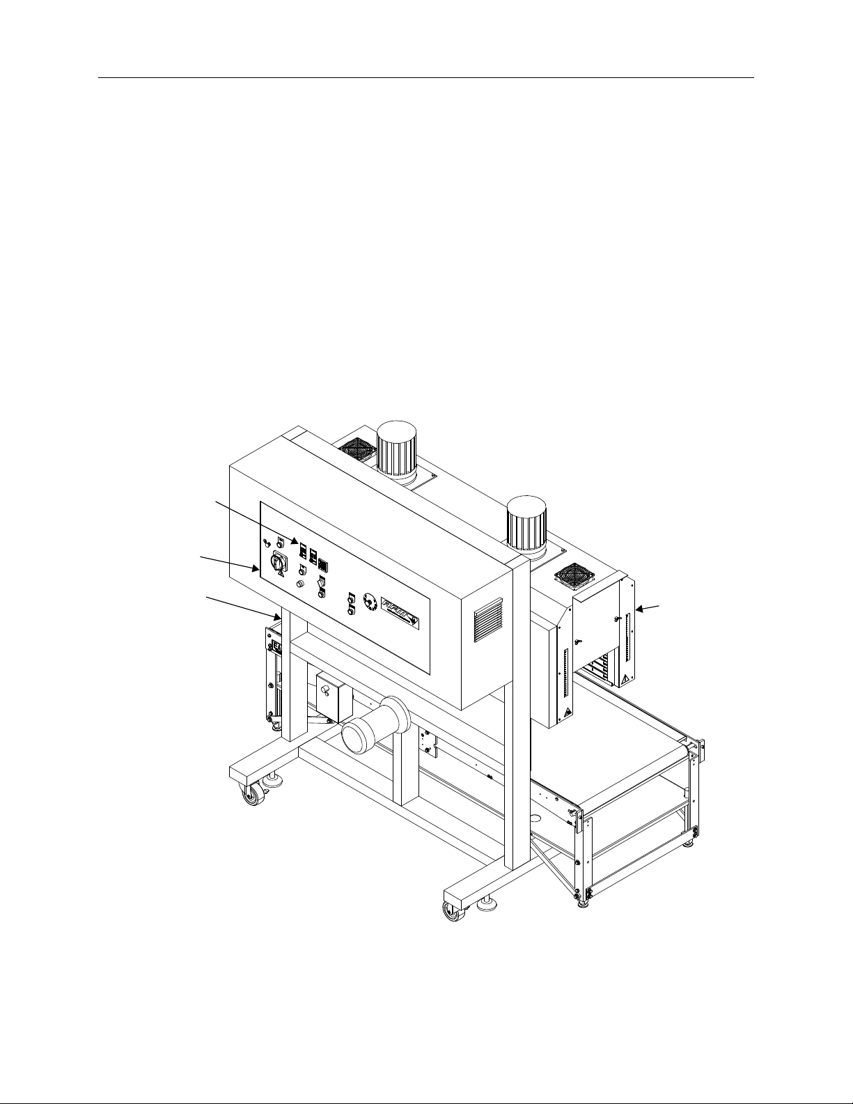
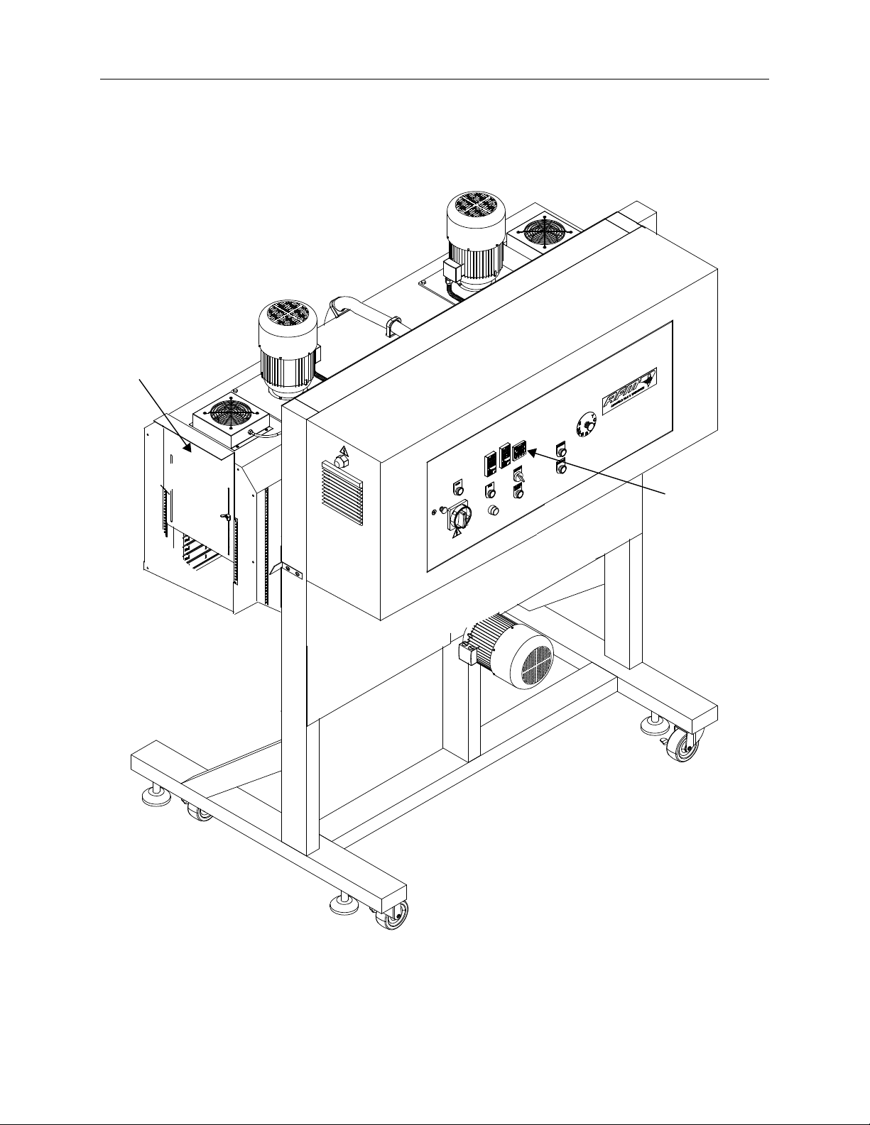
ES-200A Heat Tunnel Major Components
Control Cabinet
Heater Fan Motors
Recirculating Fans
Tunnel Exit
Height Adjustment Motor
Stand

Installation and Setup 13
4510003 Rev B
Tunnel Placement
A conveyor must be used with the tunnel to move the product while it is being sleeved.
1. Position the tunnel next to the conveyor, considering product size and location on
conveyor.
2. Ensure that all controls on both control panels are easily accessible.
3. Set the conveyor height.
4. If the tunnel height needs adjustment, connect the heat tunnel to AC power. Refer
to the “Connecting Power” section on page 14.
5. Press the Ascend or Descendbuttons as required to raise and lower the heat
tunnel.
6. When the tunnel and conveyor have been properly positioned, unscrew the leveling
feet to keep the tunnel from moving.
Tunnel Controls
Conveyor Controls
Tunnel
Feet

14 Installation and Setup
4510003 Rev B
Connecting Power
CAUTION: Before connecting power, verify that the power switches are in the OFF
position.
Connect an appropriate electrical plug to the end of the cord.
Plug the power cords from the conveyor and tunnel into properly wired and grounded
electrical outlets.
Heat Tunnel Power Cord
Conveyor Power Cord
Conveyor Power Switch
Tunnel Power Switch

Operation 15
4510003 Rev B
Operation
Startup
1. Before starting the ES-200A Heat Tunnel, double-check the installation.
2. Verity that all power cables are properly connected.
3. Turn the Heat Tunnel Power Switch located on the front of the Control Cabinet to the
ON position.
4. Turn the conveyor power switch to the ON position.
Heat Tunnel
Power Switch
Conveyor Power Switch

16 Operation
4510003 Rev B
Control Cabinet Overview
CAUTION: The control cabinet is not a watertight enclosure. Do not splash the
cabinet with liquid.
The front panel of the control cabinet includes the following:
ES-200A V2 Control Cabinet
ES-200A V2 with Conveyor Controls
Power Indicator Light
Tunnel Power Switch
Emergency
Stop Button
Heater Power Switch
Height
Adjustment
Buttons
Temperature
Control
Module
Fan Power Button
Alarm
Reset
Button
Fan Speed
Controls
Power Indicator Light
Tunnel Power Switch
Emergency
Stop Button
Heater Power Switch
Height
Adjustment
Buttons
Temperature
Control
Module
Fan Power Button
Alarm Reset Button
Fan Speed
Controls
Conveyor
Controls
Conveyor
Power
Button

Operation 17
4510003 Rev B
Running Product
1. Turn the Tunnel Power Switch to the ON position.
2. Press the ASCEND and DESCEND height adjustment buttons on the tunnel to set
the correct height for the product.
NOTE: In Manual Mode, press the ASCEND button to raise the tunnel. Press the
DESCEND button to lower the tunnel. In Auto Mode, the tunnel rises when the
conveyor has stopped. To use Auto Mode, the Conveyor Input wire must be
connected.
3. Turn on the Conveyor.
4. Turn on the Fan power button.
5. Turn on the HEATER power switch.
Fan Power Button
Heater Power Switch Ascend Button
Descend Button
Tunnel
Power
Switch

18 Operation
4510003 Rev B
Fan Control Module
Fan Control Keypad
Right Heater Fan
Left Heater Fan
Left Fan Controls Right Fan Controls

Operation 19
4510003 Rev B
The VFD-M fan control modules control each large fan motor speed. The smaller fans
on the top outer edges of the tunnel begin running automatically when the Tunnel power
Switch is turned to the ON position.
The tunnel is shipped with the fan controls set at F60.0, which equals 60 Hz or full
power of the fans.
Control Function
Program/Function key Used to change parameters and display
amperage, hertz, frequency, and counter.
LED Display key Displays settings.
LED Indicators Lamps light up for each operation.
RUN key Not used
STOP/RESET key Not used
ENTER key Saves settings and changes to settings.
UP and DOWN keys Used to raise fan speed (no higher than 60) and
to lower fan speed to slow down airflow through
the inside vents of the tunnel.
Potentiometer Refer to the VFD-M Digital Keypad Manual for
more information.
20 Operation
4510003 Rev B
Temperature Control Module
The SDC15 (Temperature Control) controls the chamber temperature in the heat zone.
Heating elements are inside the top of the tunnel and run the length of the tunnel.
After a temperature setpoint has been selected, run some product and observe the
results. To adjust the temperature, set the control to the new desired temperature.
Always wait for tunnel heat to stabilize before making changes.
Heating
Elements
Temperature
Control
Table of contents
Other AFM Industrial Equipment manuals


