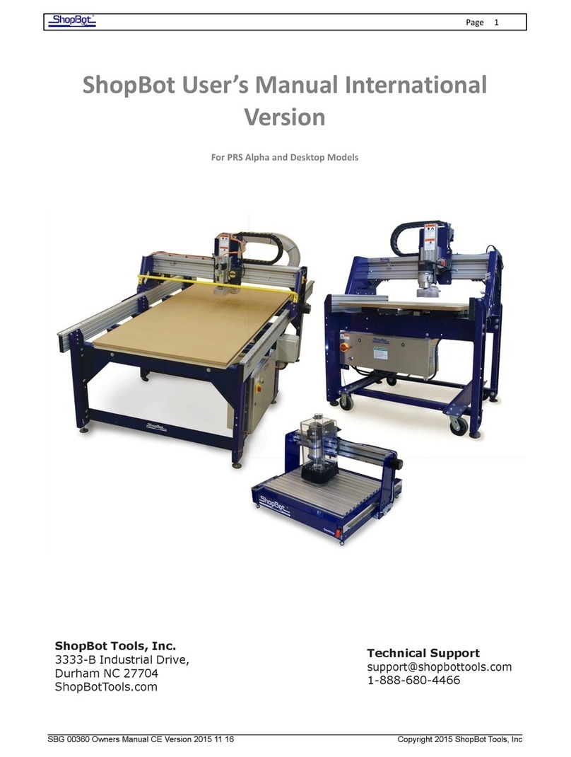
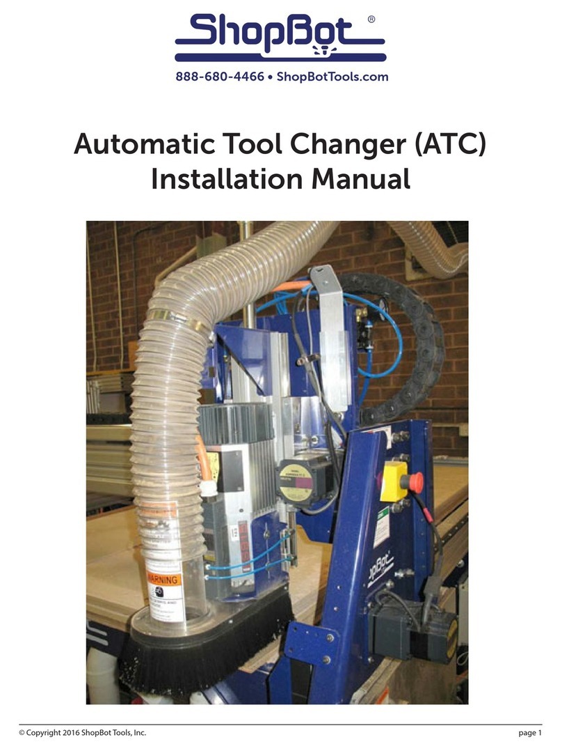
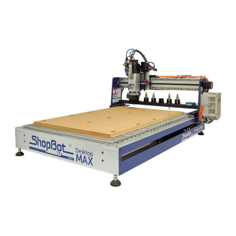
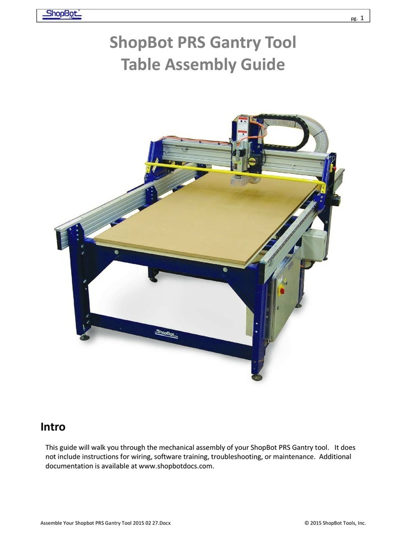
ShopBot SBG00140 User manual

© Copyright 2018 ShopBot Tools, Inc.
page 1
Automatic Tool Changer (ATC)
Installation Manual
SBG00140

Automatic Tool Changer (ATC) Installation Manual ●July 23, 2018
© Copyright 2018 ShopBot Tools, Inc.
page 2
Table of Contents
Introduction..................................................................................................................................................... 3
ATC Installation (Mechanical) ......................................................................................................................... 4
ATC Table and Spoil Board............................................................................................................................ 4
Mounting the Spindle ..................................................................................................................................... 5
Install Pneumatic Assist Line ...................................................................................................................... 5
Mount Tool Bar ........................................................................................................................................... 6
Mount Tool Chuck ...................................................................................................................................... 7
ATC Installation (Spindle) ............................................................................................................................... 8
Connecting the Pressure Switch ................................................................................................................ 8
Connecting the Spindle .............................................................................................................................. 8
ATC Installation (Pneumatic) ........................................................................................................................ 10
ATC Software Setup and Tool Calibration ................................................................................................... 12
Install the ATC Software ........................................................................................................................... 12
ShopBot Setup (TS)...................................................................................................................................... 13
Software Inputs and Outputs Check ............................................................................................................ 16
Inputs ........................................................................................................................................................ 16
Outputs ..................................................................................................................................................... 17
Basic Function Check............................................................................................................................... 17
Additional function checks ....................................................................................................................... 18
Calibration Cables ................................................................................................................................ 18
Z Zero Plate .......................................................................................................................................... 18
Fixed Z Zero Plate ................................................................................................................................ 18
Tool Draw Bar ....................................................................................................................................... 18
Calibrating the ATC ...................................................................................................................................... 19
Home Machine (C3) .................................................................................................................................. 19
Calibration Routine (CN74) ....................................................................................................................... 19
Step 1: Determine Z Height for Calibration .......................................................................................... 20
Step 2: Determine XY Position of Tool Clips........................................................................................ 21
Step 3: Set Fixed Z-Zero Plate Location.............................................................................................. 22
Step 4: Setup Tool Holders .................................................................................................................. 23
Step 5: Zero Tools in Rack (CN72) (Daily Operation) ........................................................................... 25
Step 6: Change Tools (C1) ................................................................................................................... 25
Step 7: Get Plate Offset (CN73)............................................................................................................ 26
Step 8: Zero to Various Z Heights (C2) (Daily Operation)..................................................................... 27
Regularly Used ATC Files............................................................................................................................. 27
Create a Tool Change File............................................................................................................................ 28
Spindle Warmup Routine (C5) ...................................................................................................................... 29
Run the File................................................................................................................................................... 29
If Something Goes Wrong ............................................................................................................................ 29

Automatic Tool Changer (ATC) Installation Manual ●July 23, 2018
© Copyright 2018 ShopBot Tools, Inc.
page 3
Introduction
The ShopBot Automatic Tool Changer (ATC) automates the bit changing process during projects that
require multiple tool changes. The ATC system includes a 5HP HSD spindle, a pneumatically-assisted Z-
axis, six-position tool bank standard, up to ten tool positions for our four-foot-wide tool (12 for a five-foot
and 14 for a six-foot), fixed-position Z-zero plate, chuck holder, magnetically removable dust skirt, and ATC
interface board.
The ATC reduces the time a project must remain on the machine by automatically changing bits between
cuts, thus eliminating the need to change and calibrate tools by hand. The ATC allows the PRSalpha to cut
complete projects where tool changes are required without additional inputs.
The 5HP HSD spindle assembly is fan-cooled. The ATC requires 7 scfm at 100 psi of clean, dry, un-oiled
compressed air. PORTABLE AIR COMPRESSORS ARE NOT RECOMMENDED, as they can have trouble
maintainaing this pressure reliably and have a reduced service life.
The ShopBot ATC is available in the following voltages:
(#22520) HSD ATC 5HP 220V 1PH PRS4
(#22521) HSD ATC 5HP 380/460V 3PH PRS4
(#22540) HSD ATC 5HP 230V 3PH PRS4

Automatic Tool Changer (ATC) Installation Manual ●July 23, 2018
© Copyright 2018 ShopBot Tools, Inc.
page 4
ATC Installation (Mechanical)
This section assumes that the ShopBot has been assembled using the instructions provided in the ShopBot
assembly manual. This means that the ShopBot is at a point in which it is able to connect and move under
the control of a computer. Wire/cable management may be left until the ATC installation has been
completed.
When naming sections, as in all writing, you should strive for consistency in tense. If the first section is
entitled Preparing the Workspace, the second section should be called Unpacking the Materials rather
than Unpack the Materials. Finally, make sure to use AP Style title case for your headlines.
VERY IMPORTANT!
For New Table Setups
The location of the table bed is extremely critical for an ATC tool. Excess overages in the X
dimension could mean tooling collisions, insufficient cutting area, and dropped tooling. At
the end of this section there is a table drawing that shows how the table should be set up.
Pay close attention to the relationship between table sides and the table surface.
For Previously Assembled Tables
Loosen the bolts that are attached to the table side extrusions and slide table sides in the
positive X direction until the table is in the position called out in the table drawings at the end
of this section.
ATC Table and Spoil Board
As noted in the provided table drawings, ATC tools deck mounting should be 2.75” from the front cross
support. Verify that the deck has been constructed properly at this time, or wait to complete this document
before continuing with deck assembly. Additionally ATC tools that are not equipped with Vacuum tables
require a double layer of MDF spoilboard to ensure proper clearance over the ATC toolbar.

Automatic Tool Changer (ATC) Installation Manual ●July 23, 2018
© Copyright 2018 ShopBot Tools, Inc.
page 5
Mounting the Spindle
The ShopBot ATC is equipped with a 5HP fan cooled HSD spindle. An ATC system requires a minimum of 7
scfm at 100 psi of clean, dry, un-oiled compressed air which will be internally regulated to the following
pressures:
Pressure
Purpose
60 psi (4 bar)
Maintain Positive Pressure in spindle body, prevent contamination
90-100 psi (6-7 bar)
Internal drawbar that holds tool holders in place
60-90 psi (4-6 bar)
Pneumatic assist cylinder on Z-axis that balances the weight of the spindle
Power up the ShopBot and position the YZ car so that it is in a location where
the front and back of the Z-axis may be reached.
Use the keypad mode (K) on the computer to move the Z-axis to a height close
to the table’s surface.
Position the ATC Spindle as shown (resting on the red cap) and move the Z-
axis up or down using the keypad mode until the holes in the Z-axis align with
the 4 mounting screws in the spindle plate. If the table has not yet been
assembled, temporarily place a piece of plywood across the cross supports.
Gradually tighten spindle securely to Z-axis with four pre-mounted M6 x 25
socket head screws, and four more loosely packaged M6 x 25 socket head
screws. Depending on the height you are mounting the spindle at, only 6 of the
8 screws may be able to be used.
Install Pneumatic Assist Line
The pneumatic assist line should be installed as per document SBG 00275-
PRS4 Pneumatic Assist Install at this time. Turn off the main air supply switch
and verify that the gauge reads 0 psi.

Automatic Tool Changer (ATC) Installation Manual ●July 23, 2018
© Copyright 2018 ShopBot Tools, Inc.
page 6
Mount Tool Bar
ATC toolbars are shipped pre-assembled. There are three different toolbar lengths, corresponding to 48”,
60”, and 72” wide tools. The toolbar is installed at the rear of the tool, and provides a mounting location for
tool holder clips and fixed Z-zero plate. Toolbars include six tool holders standard. Bit diameter should not
exceed 1.25” and total bit length should not exceed 5”.
To mount the toolbar, use a 1/2” wrench to loosen the 4 hex cap screws connecting each of the two toolbar
brackets such that they can be adjusted to span between the table sides. Slide T-nuts into the 4 inner slots
of the table side. Toolbar brackets should be mounted 12.5” from the table end, as per the drawing on page
7. Before tightening, level the tool bar by placing a level on top of the extrusion in both directions (along X-
axis and Y-axis of table) to ensure that the tool bar and table sides are aligned.
Note: Before fully tightening the mounting bolts, turn on the machine and move the gantry to the positive x
extreme to ensure that the spindle will reach the toolbar without hitting the mechanical stops. Mechanical
stops should be positioned such that the center of the rear gantry v-wheel’s center reaches a minimum of
0.125” from the end of the rail.
The Fixed Z-zero plate can now be wired directly
into the control box using the attached 2
conductor cable. Connect the cable to the plate
with the attached WAGO connector and wire the
black and red wires into ground and input 1 (ZZ)
respectively on the control board.

Automatic Tool Changer (ATC) Installation Manual ●July 23, 2018
© Copyright 2018 ShopBot Tools, Inc.
page 7
Mount Tool Chuck
The tool chuck is used to hold the tool holder cone while changing
collets and bits. Use 5/16”x3/4” button head screws and T-nuts to
mount the tool chuck in the second slot from the bottom of the table
extrusion. If this location is not optimal, mount the chuck where it is most
convenient, taking care not to interfere with the movement of the gantry.

Automatic Tool Changer (ATC) Installation Manual ●July 23, 2018
© Copyright 2018 ShopBot Tools, Inc.
page 8
ATC Installation (Spindle)
This portion of the installation covers spindle power and control box cabling as well as pneumatic lines.
Connecting the Pressure Switch
Locate the pressure switch on the primary air
regulator. Attach the threaded pressure switch cable
to the wire coming out of the pressure switch. Route
the two pin terminal block end into the control box.
Inside the control box, route the pressure switch
cable to the ATC interface board. Connect the blue
two pin terminal block to the location marked
“pressure switch.”
Connecting the Spindle
Using a 4mm hex wrench, remove the small socket
head screw from the front face of the spindle plug.
PRESSURE SWITCH
CONNECTOR
PRIMARY AIR
REGULATOR

Automatic Tool Changer (ATC) Installation Manual ●July 23, 2018
© Copyright 2018 ShopBot Tools, Inc.
page 9
Plug the cables into the mating plug of the HSD spindle and
secure the socket head screw to lock the plugs in place.
Route the cabling from the spindle through the Y-axis E-
chain into the control box and over to the left side of the ATC
interface board.
Before locking cables into the Y-axis E-chain, manually
move the Z-axis to both of its extents of travel to make sure
there is enough slack in the cables for the Z-axis to move
freely.
Connect the small blue terminal block to the location marked
“VFD Logic”. Ensure the wires are attached with red
connected to S4, black connected to S1, and green
connected to SC.
The spindle sensor cable has a 12 pin male Wago connector
and will connect into the corresponding female piece on the
ATC board.
Find the female Wago connector on the board identified as
“spindle sensor cable.” Connect the male Wago connector
into the ATC interface board.

Automatic Tool Changer (ATC) Installation Manual ●July 23, 2018
© Copyright 2018 ShopBot Tools, Inc.
page 10
ATC Installation (Pneumatic)
Using a 4mm hex wrench and adjustable wrench, connect the ATC manifold to the Y-Echain Bracket on the rear of
the YZ car using the pair of pre-mounted hardware as shown above.
Run the ferruled side of the 3-conductor 30’ ATC cable from
the pneumatic manifold through the Y and X cable carriers
and into the control box and to the ATC interface board as
shown in the picture to the right.
Black to +24V
Green to GND
Red to TR + under Tool Release

Automatic Tool Changer (ATC) Installation Manual ●July 23, 2018
© Copyright 2018 ShopBot Tools, Inc.
page 11
The 3/8” hose with a T-fitting on the end can now be run to
the regulator. The T-fitting should be inserted into the
regulator stem first as shown in the picture at right.
Run the 2 1/4” blue tubes included with the pneumatics
manifold from push-in connectors on the manifold to the
push-in connectors marked 5 and 2on the spindle.
The spindle’s push-in connector marked 5 should connect to
the lower of the 2 push-in connectors on the manifold (this is
the spindle’s drawbar which will actuate tool pickup and
release).
The spindle’s push in connector marked 2 should run to the
upper of the 2 push in connectors on the manifold with a
regulator (this is supply for positive pressure air to the
spindle which will remain open when the tool is on).
Turn on the pneumatics switch at the filter regulator manifold and verify that the pressure here is between
90 and 100 psi.
The small regulator for the spindle’s positive pressure should be set to 60 psi (note that the gauge reads
in 1/10ths). The red LED on the positive pressure solenoid should be on.
UPPER (2)
LOWER (5)

Automatic Tool Changer (ATC) Installation Manual ●July 23, 2018
© Copyright 2018 ShopBot Tools, Inc.
page 12
ATC Software Setup and Tool Calibration
This portion of the installation covers the software setup and tool calibration.
Install the ATC Software
Download the latest ShopBot control software from the ShopBot website:
http://www.shopbottools.com/mSupport/controlsoftware.htm
If an earlier version of the ShopBot control software is present, uninstall the software and install the most
recent version. Refer to “Uninstall/Reinstall ShopBot and VCarve Software”
at http://www.shopbottools.com/ShopBotDocs/software.htm
Note: If there are personal files within the “SbParts” folder, be sure to rename or move this folder so the
files are not lost.

Automatic Tool Changer (ATC) Installation Manual ●July 23, 2018
© Copyright 2018 ShopBot Tools, Inc.
page 13
ShopBot Setup (TS)
Type in “UR” or go to “Utilities” pull-down menu and select “Reset default Settings”. Select the file name
that correctly describes the table size, making sure it ends with ATC.
Move the cutter to the location that is to be “0, 0” (the reference point for programming) on the
table. Open the ShopBot control software and open the “ShopBot Setup” file in the “Tools” drop-
down (TS). Read through the window and click “Next”. The second window is the “Tool Settings”.
Go step-by-step through this window while verifying information about the machine. Make sure
that the check boxes for the Z zero plate and proximity switches are checked at the bottom of the
window. Select the radio button marked ATC4. (If your ATC tool has a pneumatically actuated
dust foot please call ShopBot for support and an alternate document).
MOVE TOOL HERE

Automatic Tool Changer (ATC) Installation Manual ●July 23, 2018
© Copyright 2018 ShopBot Tools, Inc.
page 14
In the “ShopBot Setup (Z Zero Plate)” screen, measure the
thickness of the plate and enter that value. Make sure the input
switch is set to “1”. DO NOT check the “Yes, I want to always
zero my Z axis at the same place on my table”. Click “Next”
.
At the “ShopBot Setup (Prox Switches)” screen, select
“Make it easy on me…” and click the “Click Here To Make It
Easy On Me” button to start the zeroing routine.
The next screen is “X and Y axis zeroing setup”. Read this screen and click
“Run the prox switch setup routine”.

Automatic Tool Changer (ATC) Installation Manual ●July 23, 2018
© Copyright 2018 ShopBot Tools, Inc.
page 15
Follow the prompts from the pop-up screens. Select “Yes”
to open the keypad for any adjustment to the “0, 0” home
position, then click “OK”.
Move the machine to the zero point, and hit “ESC” to exit the keypad
mode.
Click “Yes” to zero out the X and Y axes and click “OK”.
Read through the “ShopBot Setup (Finished)” window and click
“I’m done.”

Automatic Tool Changer (ATC) Installation Manual ●July 23, 2018
© Copyright 2018 ShopBot Tools, Inc.
page 16
Software Inputs and Outputs Check
Ensure that all of the inputs and outputs are being recognized by the automatic tool changer (ATC) by
checking for each of the cases outlined in this section.
Inputs
Inputs are signals that the software receives from devices that cause the tool to have a specific reaction.
Input 1 –The Z zero plate and the fixed Z zero are connected to this input. When either of these
plates are connected to a ground, the circuit is closed and input “1” on the ShopBot position
screen lights up. The tool’s fixed z-zero plate does not require a grounding clip, however use of
the standard z-zero plate does.
Input 2 –The X-axis proximity switch is connected to this input. During normal operation, the input
“2” light will be off in the ShopBot position screen. If the X-axis proximity switch passes the
proximity targets, the light will turn on. Among other things, this feature will be used for homing
the X and Y positions and for limiting the safe table cutting boundaries.
Input 3 –The Y-axis proximity switch is connected to this input. During normal operation, the input
“3” light will be off in the ShopBot position screen. If the Y-axis proximity switch passes the
proximity targets, the light will turn on. Among other things, this feature will be used for homing
the X and Y positions and for limiting the safe table cutting boundaries.
Input 4 –This input is connected to the stop switch. When active, the switch allows for use of the
tool and when inactive, the connection is severed and the tool comes to a stop.
Input 5 –The Z-axis proximity switch is connected to this input. During normal operation, the input
“5” light will be ON in the ShopBot position screen. When the Z-axis proximity switch passes the
proximity targets, the light will be turned OFF. This switch will be used most often for a reference
location in zeroing the bits in the tool rack and for limiting the safe Z cutting boundary.
Input 6 –NA
Input 7 –Drawbar closed. Lights when tool holder is properly inserted into spindle and clamped.
Input 8 –Drawbar open. Lights when tool holder is ejected.

Automatic Tool Changer (ATC) Installation Manual ●July 23, 2018
© Copyright 2018 ShopBot Tools, Inc.
page 17
Outputs
Outputs are signals that ShopBot software is sending to cause a desired action. Unused outputs can be
programed to activate other peripherals using an optional relay board.
Output 1 –Runs the spindle.
Output 2 –NA
Output 3 –Toggles the ATC dust skirt gate open.
Output 4 –Turns on during machine operation (safety flashing screen). Required for spindle “on” signal.
Output 5 –NA
Output 6 -NA
Output 7 –NA
Output 8 -Toggles the spindle drawbar open /close (releases tool holders from spindle).
Caution: When the spindle is not spinning it is possible to drop the tools from the spindle if Output 8
is activated.
Basic Function Check
Check that all systems involved are working properly, starting with the proximity switches.
In keypad mode (K) move the X-axis into the proximity target
using the left arrow on the keypad. The proximity switch will
have a red LED lit until it comes across the proximity target,
when it will turn off. Moving off the top of the target should
cause the LED to come back on. This should also be evident in
the ShopBot position screen when looking at input “2”, the light
will turn from black (normally closed) to green (open).
In keypad mode (K), move the Y-axis into the proximity target
using the down arrow on the keypad. The proximity switch
will have a red LED lit until it comes across the proximity
target, when it will turn off. Moving off of the target should
cause the LED to come back on. This should also be evident
in the ShopBot position screen when looking at input “3”.
In keypad mode (K), move the Z-axis into the proximity target using “Page Up” on the keypad. The
proximity switch will have a red LED lit until it comes across the proximity target, when it will turn off.
Moving off the top of the target should cause the LED to come back on. This should also be evident in the
ShopBot position screen when looking at input “5”. Input “5” will appear green until the target is hit then the
input goes black.

Automatic Tool Changer (ATC) Installation Manual ●July 23, 2018
© Copyright 2018 ShopBot Tools, Inc.
page 18
Additional function checks
Calibration Cables
To check calibration cables, insert plug end of the calibration and grounding clip into socket
located on the YZ car. If the Z zero plate is connected to this socket, you will have to unplug it to
connect the calibration cables. The calibration clip will be designated by the red grips and the
grounding clip by the black grips.
Touch the calibration clip (red) to the grounding clip (black) and make sure that input “1” lights up
green on the ShopBot position screen.
Z Zero Plate
To check the Z zero plate, insert the plug end of the Z zero plate cable into the socket locate on
the YZ car. If the calibration cables are connected to this socket, you will have to unplug them to
connect the Z Zero plate.
Touch the Z zero plate grounding clip to the Z zero plate and make sure that input “1” lights up
green on the position screen.
Fixed Z Zero Plate
To check the fixed Z zero plate, simply press down firmly on the
plate. Input “1” should light up green on the position screen while
the plate is pressed. The light should go off again when the plate is
released.
Tool Draw Bar
Make sure your compressed air supply is on for the following checks.
Press the green button on the side of the spindle. While the button is
depressed the internal draw bar will open, allowing the spindle to accept

Automatic Tool Changer (ATC) Installation Manual ●July 23, 2018
© Copyright 2018 ShopBot Tools, Inc.
page 19
tools. While the draw bar is open, a rish of air will be heard, and input “8” will be lit.
With the green button still
depressed, insert a tool holder into
the spindle and hold it there.
Release the green button. The
drawbar will close, capturing the
tool holder. Input “7” should light
up, and input “8” should turn off.
Calibrating the ATC
Home Machine (C3)
Type C3 in the ShopBot 3 software or use the XY home icon in the position window. The tool should end up
at the home location previously set in the ShopBot Setup routine.
Calibration Routine (CN74)
The ATC calibration routine (CN74) is programmed to find
and record the clip locations. This document will walk
through the process.
Take out the calibration clip and drill rod that came with
the ATC. Connect the Wago plug to the mating socket on
the YZ car. The grounding clip is also attached to this
same plug.
The red calibration clip will be clipped to the bottom of
an empty tool holder as it is moved through all of the clip positions.
The black clip is will be clipped to the tool holder that is in the spindle.
Type “CN74” into the ShopBot 3 software to begin the routine. Enter the number of tool clips that are
mounted on the ATC.
Click yes if X and Y were zeroed. Otherwise, click “No” and return to the Homing the Machine (C3)
step.

Automatic Tool Changer (ATC) Installation Manual ●July 23, 2018
© Copyright 2018 ShopBot Tools, Inc.
page 20
Step 1: Determine Z Height for Calibration
Press the green button located on the side of the spindle, and
insert an empty tool holder.
Place a second, empty tool holder, inverted in clip position #1.
Use the keypad to move the spindle over the inverted tool
holder in clip position #1. Position the two faces about 1 inch
apart and visually center the top tool holder over the inverted
one as closely as possible. Hit “ESC”.
Place the black grounding clip on the tool holder in the spindle.
Table of contents
Other ShopBot Industrial Equipment manuals
Popular Industrial Equipment manuals by other brands
Siemens
Siemens SIRIUS ACT 3SU19 operating instructions
Tenco
Tenco ENOL MASTER Technical handbook
Bell
Bell VSD 42/12 Manual for use and maintenance
Endress+Hauser
Endress+Hauser Flexdip CYA112 operating instructions
Stahl
Stahl SolConeX 8573/14 Series operating instructions
Festo
Festo 152962 operating instructions
