AFM LX-150 User manual

Shrink Sleeve Label Applicator
Model Number LX-150
User Guide


AFM
Shrink Sleeve Label Applicator
Model Number LX-150
User Guide
Revised 9/11/2017
P/N 4510001 Rev A
Copyright and Trademarks
Copyright ©2017 American Film and Manufacturing.
All rights reserved. All trademarks and brand names
are the property of their respective owners.
AFM
15214 Pomona Road
Corona, CA 92880
Phone: (714) 974-9008; Fax (763) 795-8867
www.afmsleeves.com


Contents:
Safety.........................................................................................................8
Introduction.............................................................................................11
System Components................................................................................................... 11
System Dimensions (in mm) ....................................................................................... 12
System Specifications................................................................................................. 13
Cutter unit sizes .......................................................................................................... 13
Description and Main components.............................................................................. 14
Installation and Setup.............................................................................16
Location Requirements ............................................................................................... 17
Data Cable and Power Connections ........................................................................... 18
Air connections............................................................................................................ 19
Operation.................................................................................................20
Before Running Product.............................................................................................. 20
Sequence of Operation ............................................................................................... 20
Power Switch ......................................................................................................................20
Threading Film ............................................................................................................ 25
Film Path..................................................................................................................... 27
Changing/Installing/Adjusting Mandrels ...................................................................... 28
Conveyor.............................................................................................................................33
Motion Detector Sensor (product trigger).............................................................................33
Typical setup.......................................................................................................................39
Diagnostic definitions ..........................................................................................................45
Testing.....................................................................................................47
Power Up .................................................................................................................... 47
Power Switch ......................................................................................................................47
With the Print Reading Sensor Turned OFF: .......................................................................48
With the Print Reading Sensor Turned ON:.........................................................................51
Determining the label length with a ruler..............................................................................52
Maintenance............................................................................................55
Changing Cutter Blades..........................................................................55
Remove Cutter Assembly....................................................................................................57
Change Blades....................................................................................................................58
LX-150 ........................................................................................................................ 59
Weekly ................................................................................................................................59
Every three weeks...............................................................................................................59
Every six months.................................................................................................................60
Annually ..............................................................................................................................60
Every two to three years......................................................................................................61
Unwind System ........................................................................................................... 61
Daily....................................................................................................................................61
Every six months.................................................................................................................61
Every two years...................................................................................................................61

Frequency ...........................................................................................................................62
Troubleshooting ......................................................................................63
General ...............................................................................................................................63
Specific problems while running machine............................................................................65
Motion Detector.......................................................................................67
Motion Detector Sensor Details................................................................................... 67
Motion Detector Sensor Setup .................................................................................... 68
Print Reading Sensor details....................................................................................... 69
Print Reading Sensor setup ........................................................................................ 70
Touch Panel Screen (HMI) ......................................................................71
Operation Appendix ................................................................................77
Screens....................................................................................................................... 77
Exploded Assembly Diagrams ................................................................84
Schematic Diagrams...............................................................................93
Parts List ...............................................................................................104
Warranty Statement AFM Products......................................................107
Customer Support .................................................................................111

Safety 7

8 Safety
Safety
The AFM Shrink Sleeve Label Applicating Machine is easy to install, operate and
maintain. Please follow these safety steps to insure smooth and safe operation:
All operators should study this manual thoroughly before operating the machine.
xAlways follow GMP (Good Manufacturing Practices) when operating this machinery.
xThe machine is heavy. While unpacking and setting up the unit, always take care to
use proper lifting techniques. Avoid over-reaching and leaning over while handling the
machine and accessories. Use more than one person to lift and move the labeling
system (four is recommended), or use a minimum 1.25-ton forklift.
xWear safety shoes and work gloves when moving the machine.
xBeware of uneven spots on the factory floor, as the machine could tip over.
xMake sure the electrical power source is properly wired and grounded. The power
source should comply with all safety regulations and codes applicable to the
installation location.
xBefore attempting any service or repair, make sure that the power is turned off and
power cable is disconnected from the power source.
xBefore connecting the air supply, make sure that the pressure gauge is closed and
that the pressure indicator reads zero.
xThe equipment generates heat, so make sure the area is properly ventilated.
xDo not place any body parts or tools into a running machine!
xTurn off and unplug the machine while servicing and performing maintenance
procedures.

Safety 9
xBe sure to use correct lockout/tagout procedures when performing maintenance and
repairs on this machinery.
xThe blades used on this machine are extremely sharp. Handle with extreme care.
Preferably use cut-resistant gloves when replacing blades.
xNever remove any GROUND connection from this equipment. Failure to follow this
directive could result in damage to the equipment, fire, serious personal injury, or
death.
xKeep water away from the electrical enclosure (at the rear of the machine), the control
panel, and all other electrical components.
xThis machine is protected by hardware MCR and E-STOP and door safety interlocks.
Under no circumstances should these be disabled.
xThe LX-150 incorporates line-control interlocks which may allow it to start
automatically, without warning.
xTake care when lifting heavy rolls of labels. If lifting from ground-level be sure to lift
with the large muscles of your legs.
xAlways consult with AFM before making any modifications to the electrical circuitry or
PLC program.
xAlways replace fuses and other protective circuit devices with those of the appropriate
current rating.
xWhen working with glass containers always wear safety glasses with side-shields.
xSome shrink label materials contain toxic chemicals. Be sure to store and dispose of
properly.
xE-STOP and safety doors should never be used to stop the machine; E-STOPS are
for EMERGENCY ONLY; safety doors should only be opened once the machine has
come to a stop. Failure to follow these directives could result in damage to the servo
drives and VFDs.

10 Safety
Ensure that machines are grounded.
Crush hazard. Do not place hands or other objects on moving mechanism. Shut
down machine before doing any maintenance or troubleshooting.
Cut hazard. Do not place hands or other objects on moving mechanism. Shut
down machine before doing any maintenance or troubleshooting.
Electrical hazard. No user serviceable parts. Keep out of power supply.
Keep equipment dry and inside.
Introduction 11
Introduction
The LX-150 Shrink Sleeve Label and Tamper-Evident band applicator is designed for
middle, full-body, and full-body and cap applications. It is designed for low-to-moderate
production rates for industries such as food and beverage, pharmaceutical, nutraceutical,
health and beauty, and other manufactured goods. It can be used for horizontal or vertical
perforation applications.
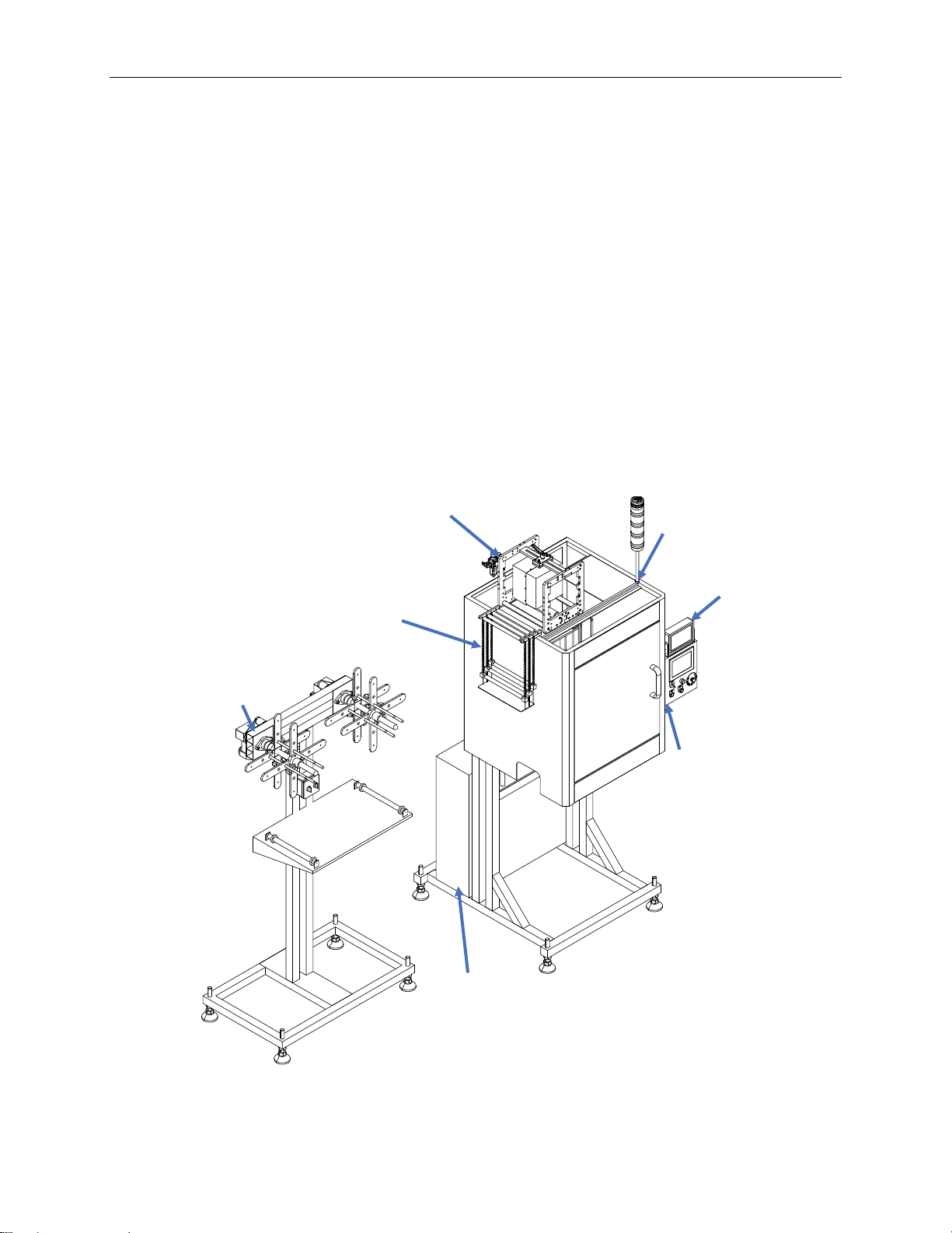
System Components
xLX-150
xPower supply
xHMIs
xUnwind station
xTTO
xDancer
1400
LX-150
HMI
Unwind
Station
Dancer
TTO
TTO
HMI
Power Supply
LX-150

12 Introduction
System Dimensions (in mm)
1730-2280
1000
1000
900
1860
1439

Introduction 13
System Specifications
Power: A.C. 3-Phase, 220 Volt, 50/60Hz
Motor: 60W X 2, 90W X 1,750 X 2
Film Width: 40-240mm
Length: 40-200mm
Thickness: 0.035-0.07mm
Applied Material: OPS, PET, PVC
Speed: 300 BPM Max. (PET Film, cut length 100mm)
Speed will vary with the shape and types of items, thickness, and length of shrinkable
film. Correct speed can be determined by actual running conditions.
Reference formula: objects diameter + 1.5~2mm x 1.57.
Cutter unit sizes
Cutter size Approximate bottle
diameter
Label layflat widths
Small (4 blade) Ø30 ~Ø70 48 ~ 115mm
Medium (5 blade) Ø50 ~Ø110 78 ~ 175mm
Large (6 blade) Ø0~Ø140 140 ~ 220mm
14 Introduction
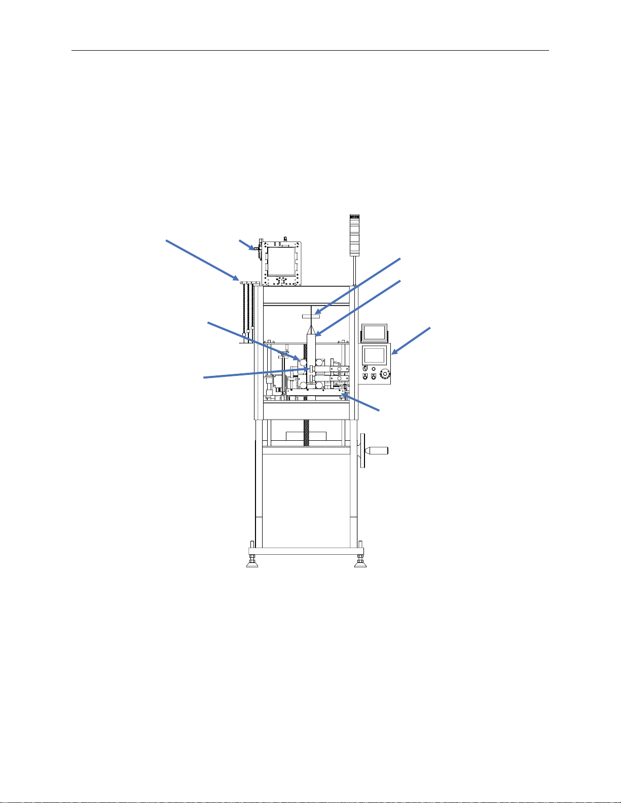
Description and Main components
The AFM LX-150 shrink sleeve labeler feeds tubular plastic film (OPS, PET, PETE,
PVC, PLA, etc.), opens it around a Mandrel (former or “bullet”), cuts the film to the
required length and places it on the containers passing under the mandrel. The film cut-
length can either be triggered by an eye-mark on the film (print-registration mode, using
the transition between opaque and clear on the printing of the film) or can be based
upon a fixed number of pulses generated by the encoder of the Film Feed Drive motor
(NO PRINT mode, selectable from the SETTING screen).
With the addition of the perforator option, each label can be perforated on the machine
to offer tamper-evidence, or to facilitate removal by the consumer.
The Film Feed Rollers feed the film by one label cut length each cycle, and the Wheels
on the Applicator assembly shoot each cut label onto the container; the cut > film-feed
cycle is triggered by the approach of the container, as detected by the Motion Detector
Sensor Eye. The label at the base of the Mandrel is first cut; then, as the feed cycle
begins, it is pushed down into the path of the (continuously rotating) Applicator Wheels,
which shoots the label onto the container.
1403
Mandrel
Support
Roller (4)
Film
Feed
Roller (4)
Cutter
Dancer TTO
HMI
Print -
Reading
Sensor
Introduction 15
The Dancer system on the LX-150 is designed to maintain back-tension in the film, to
maintain correct registration for the Cutter, and to give a cut with minimal tails and burrs.
The Obstruction (Jam) Sensor monitors each label as it passes under the Mandrel and
stops the machine automatically if a label fails to make it down below the Mandrel, or if
a label becomes stuck at the base of the Mandrel (not shown-see page 34 for location).
Conveyor Side-belts and Brush-down units are two optional extras which can be used,
depending upon the application. The Side-belts are generally not used in cases where
the bottom of the label is to come down all the way to conveyor level; in cases where
the label is designed to stop part of the way down the container, or is a shoulder label,
the Side-belts can be used to support the bottom of the label as it is applied to the
container.
Brush-down may be necessary when the labels fail to consistently go down to the
desired height on the container (for example, when the containers coming into the
machine are wet).
The LX-150 must be used in conjunction with an appropriate film unwind device
(typically AFM AUS40 or UR). Since the LX-150 is a shrink sleeve labeler, a Heater
Tunnel (steam, convection or infrared) must be used also.
1602
Side Belt
Shoulder Label

16 Installation and Setup
Installation and Setup
The LX-150 will have been pre-tested with your product prior to shipment.
Included in box:
xLX-150
xUnwind
Optional:
xConveyor
xTTO
xHorizontal perforator
xVertical perforator
xHeat tunnel
xTiming screw
xSide Belts
Please see your dealer for any optional equipment purchases.
Installation and Setup 17
Location Requirements
xPlace machine in the location where it can be easily accessed from all sides.
xEnsure that unit is level. Adjust levelling using the levelling feet.
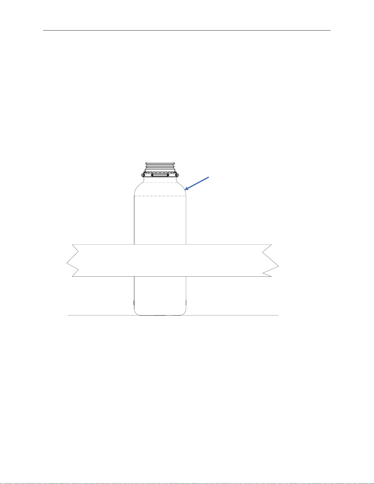
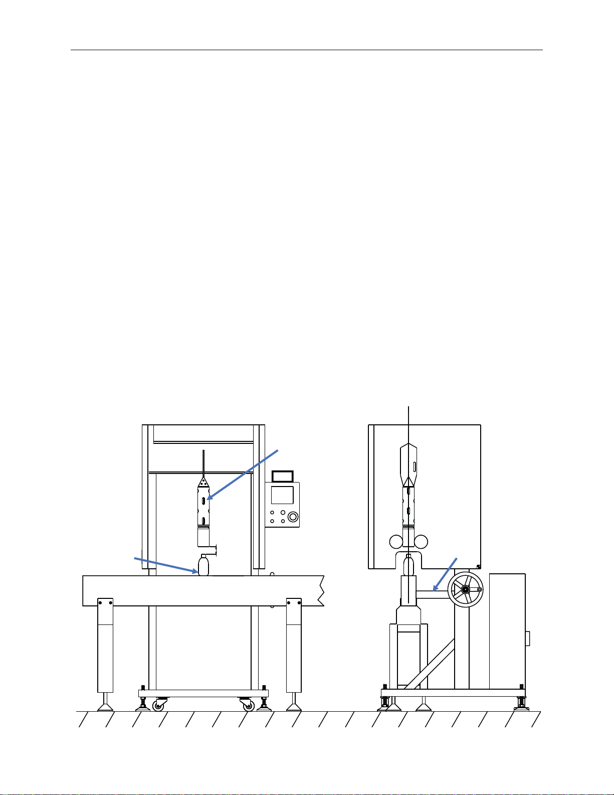
xAlign the mandrel with the center line of the conveyor.
xAdjust the height of the machine by turning the adjustable feet until the space (A) from
the top of the container to the bottom of the mandrel (B) is approximately half the
length of a label. When this has been completed, tighten the adjustable feet. Most of
the adjustment to set the height of the mandrel, relative to the top of the container, is
accomplished with the crank on the side of the labeler. The leveling mounts should
just be used to put the LX150 at a height where both the shortest and tallest bottles
can be accommodated.
xSecure the conveyor to the machine using a brace.
xAfter verifying that the supply voltage matches the voltage shown on the name-plate
and on the electrical schematics, connect the three-phase power.
xInstall the timing screw assembly so that the screw ends at least 12 inches upstream
of the Mandrel.
1381
A
Container C
B
Mandrel
Conveyor
18 Installation and Setup
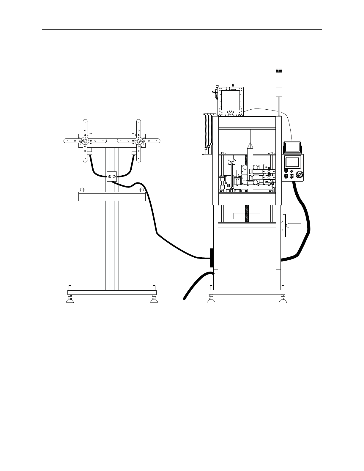
Data Cable and Power Connections
Connect HMI, Touchscreen, and Unwind Station before plugging into power. Make sure
power switch is set to “off” before plugging in. Do not “hot plug” any of the assemblies.
To 220V AC
Power
Supply
HMI
TTO
Unwind
Station
1380

Installation and Setup 19
Air connections
With air turned off, connect air hose to TTO (if using TTO for date/time coding).
1511
Connect air

20 Operation
Operation
Before Running Product
Before running product, be sure to check the following:
1. Container Conveyor Guide-widths and Timing Screw position should correspond
to the width of the container and centering of the Mandrel on the conveyor.
2. Check that the Mandrel is installed securely (see page 28).
3. Use MANUAL MODE to verify the correct cut and, when applicable, perforation
position (see page 32).
4. Use a container to make sure that the Brush-down units are set correctly (if
applicable).
5. Verify that your Heater Tunnel is set up correctly.
6. Verify that the Motion Detector Sensor eye is at the correct height – usually to
detect the leading edge of the cap of the product.
Sequence of Operation
Power Switch
To power up the LX-150, turn the power switch located on the back panel of the power
supply to the “ON” position.
1401
Power
Switch
Other manuals for LX-150
1
Table of contents
Other AFM Industrial Equipment manuals


