Stober K38-03 User manual
Operating manual
Brakes for Asynchronous Motors / Asynchronous Motors IE2
107/2014
WE KEEP THINGS MOVING
ID 442015_en.04
en
This operating instructions is a supplement to the operating
instructions "System Motors / Asynchronous Motors".
The electromagnetically operated, twin-surface spring
pressure brake is applied by spring force when not energised
and is released by an electromagnetic DC coil (Fig. 1, pos. 2)
or, when stationary, by an optionally installed manual valve
(Fig 1, pos. 3). The DC coil can be supplied either directly with
direct current or with an alternating current via a brake
rectifier (bridge, single-phase or Powerbox, see information
on the specification plate). When a direct DC supply is
provided (without a rectifier), a varistor must be installed as
protection against switching surges.Observe the information
in the STÖBER catalogue, on the braked motor specification
plate, in the operating instructions, wiring diagrams and
safety instructions.
If in doubt or when documents are lacking, obtain the
necessary information from the pertaining STÖBER sales
office or service workshops.
1 Technical data
Technical data for brake see appendix.
1.1 Electrical features Powerbox
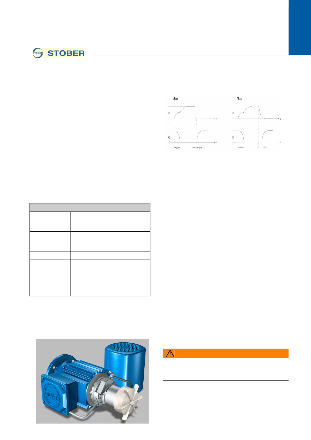
1.2 Current and torque-time diagram in
dependency on the circuit
arrangement
It is appropriate to switch on the brakes by the respective
switch-on time t2 before the motor.
See also Item 3, Electrical connection.
1.3 Formula brake
MB[Nm] - Braking torque
P20 [W] - Power input in continuous operation at 20° C
WNR [106·J] - Friction work until next adjustment,
amplification factor for Powerbox see below!
(WNR=10·W01·(Lmax-LN))
W01 [106·J] - Friction work per 0.1 mm of wear
LN[mm] - Rated air gap
Lmax [mm] - Maximum air gap
gmin [mm] - Min. permissible lining thickness
t2[ms] - Switch-on time (brake release time) up to M = 0 Nm
t11 DC [ms] - Switch-off time (delay) at S DC
t11 AC [ms] - Switch-off time (delay) at S AC
JB[10-4kgm2] - Mass moment of inertia
UDC [VDC] - Brake voltage
UAC [V] - Brake rectifier voltage
t2P [ms] - Powerbox switch-on time (brake release time) up to
M = 0 Nm
t11DCP [ms] - (delay) at S DC with Powerbox
t11ACP [ms] - (delay) at S AC with Powerbox
WNRP/WNR - Friction work until next adjustment, Powerbox
(amplification factor)
IB- Brake current
ZS[1/min] - Permitted switching cycles per minute (a
switching cycle consists of switching on and off once)
2 Installation, adjustment /
readjustment of the air gap (Fig. 1)
WARNING!
For work on the brake:
XSecure machine against unintentional movement
(vertical load, etc.).
The brakes are installed on the drive upon delivery and the
braking torque and air gap are adjusted to their rated values.
Air gap setting:
Adjust the air gap “L” to the rated value (LN) when the
maximum air gap (Lmax) is reached due to wear:
- Remove fan guard (1).
Powerbox electrical properties
Powerbox for use
with Frame size 63 - 132: Terminal box or
switch cabinet;
Size 160 - 225: only in switch cabinet
Input voltage 180 - 300 VAC +/- 0%
can be used for a wide range
220 - 275 V +/- 5% 50 or 60 Hz
Excitation time 350 ms +/- 10%
Cable length max. 100 m of brake coil
Current IN45°C 1,2 A stable;
2,4 A for 350 ms
Current IN75°C 0,7 A stable;
1,4 A for 350 ms

Operating manual
Brakes for Asynchronous Motors / Asynchronous Motors IE2
2
ID 442015_en.04
WE KEEP THINGS MOVING
07/2014
en
- Loosen cheese-head screws (5).
- Adjust the air gap to the rated value by applying an open-
jawed spanner to the adjusting nuts (4). Two calliper gauges
are necessary to measure the air gap; the deviations at the
three measuring points should not exceed ±0.05 mm.
- Tighten cheese-head screws (5).
- Replace fan guard (1).
Replace brake:
When the minimum lining thickness gmin is reached, replace
brake disc (6). During the replacement, inspect the anchor
disc (7), lining (motor B bearing bracket), friction disc (8) and
brass foil (if installed). Replace if excessively worn. Anchor
disc (7) available only complete with brake coil (2).
Fig. 1
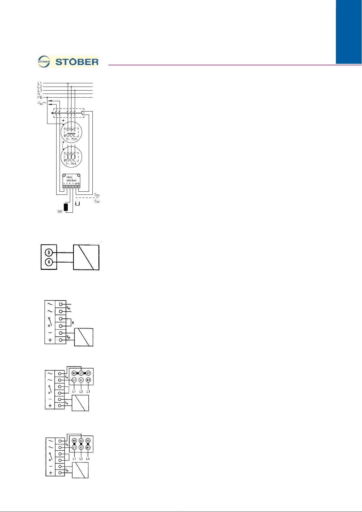
3 Electrical connection
- Without rectifier, connected voltage UDC see specification
plate (Fig. 3)
- With rectifier and external supply UAC (Fig. 2, Fig. 4) fast
rectfier (Powerbox) also included.
See specification plate for connected voltage UAC.
AC switching (with bridge B).
DC switching (fast application of the brake).
Remove bridge B in Fig. 2, replace with switch contacts and
employ additional AC switching.
- With rectifier and direct UAC supply from the motor
terminals.
Install the enclosed connecting bridges as shown in Fig. 5 and
Fig. 6.
The following applies for connected voltage of the brake
(UAC) according to specification plate and supply voltage
(U3AC):UAC = U3AC x 0.58 (Fig. 5), UAC = U3AC (Fig. 6).
Connection of the brake to motor terminals possible only
when the voltages are equal.
Permissible only for direct starting with supply.
Connected voltage with Powerbox rectifier 220 - 277 VAC, coil
voltage 115 (or 127) VDC.
Observe terminal designations on the component.
For other designs or other installed equipment, see separate
circuit diagram.
While making the motor connection, observe and comply with
the attached safety instructions and the respective operating
instructions. Observe connection designation and connection
plan!
To be observed while using rectifiers:
If the full nominal power is used, or if the motor is driven only
with its own ventilation in the lower speed range (at drive
controller), then it is possible for the temperature of the motor
housing surface to exceed the maximum permissible
ambient temperature for Powerbox fast rectifier (75° C) or
for one-way or bridge rectifier (80° C). In this case, installation
in the terminal box is not advisable, as the higher
temperatures can lead to the premature failure of the rectifier.
Instead, the rectifier should be installed in the control cabinet.
Of course, here too, a position should be selected at which
the temperature is always lower than the permissible ambient
temperature! For use under increased temperature
conditions, or operation through drive controllers, we request
you to please discuss the matter with our sales engineers.
Operating manual
Brakes for Asynchronous Motors / Asynchronous Motors IE2
307/2014
WE KEEP THINGS MOVING
ID 442015_en.04
en
Fig. 2
Fig. 3
Fig. 4
Fig. 5
Fig. 6:
4 Troubleshooting
In the event of a malfunction of the drive unit, call the
STÖBER service department at 07231 582-1190 (-1191, -
1224, -1225) in order to locate the nearest STÖBER service
partner for further action.
In urgent cases outside of normal business hours, you
can call the STÖBER 24-hour service hotline at 01805
786323 / 01805 STOEBER
5 Spare parts
Include the following when ordering replacement parts:
– item no. of the part according to the replacement parts lis
– model designation according to the rating plate
– serial number according to rating plate
You can reach the STÖBER replacement parts service by
phone: 07231 582-1190 (-1191, -1224, -1225), or fax: 07231
582-1010.
Important notice: The replacement parts lists are not
assembly instructions! They are not binding for assembly of
the gear unit. Use only original replacement parts from
Stöber. Otherwise we will provide no guarantee and will
assume no liability for resulting damages!
6 Disposal
This product contains recyclable materials. Observe local
applicable regulations for disposal.

Operating manual
Brakes for Asynchronous Motors / Asynchronous Motors IE2
4
ID 442015_en.04
WE KEEP THINGS MOVING
07/2014
en
7 Appendix
Technical data:
Technical data for standard wide-range brakes with high-
speed rectifier:
Typ Mot. M
B
P
20
W
NR
W
01
L
N
L
max
g
min
t
2
t
11DC
t
11 A C
J
B
m
B
[Nm] [W] [10
6
J] [10
6
J] [mm] [mm] [mm] [ms] [ms] [ms] [10
-4
[kg]
kgm
2
]
K38-03 80K,80L 10 30 37,5 12,5 0,2 0,5 6,5 55 15 100 0,79 1,7
K38-04 90L,90S 20 30 76,0 19,0 0,2 0,6 8,0 90 25 180 1,50 3,3
K38-05 100K,100L 36 48 112,0 28,0 0,2 0,6 10,0 110 25 220 3,85 5,0
L48-14 112M 60 50 215,0 43,0 0,3 0,8 6,0 150 65 390 6,93 5,7
L48-16 132M,132S 80 55 434,0 62,0 0,3 1,0 7,5 180 90 540 16,5 8,7
L48-18 160K,160L,160M 150 85 540,0 90,0 0,4 1,0 8,0 300 110 660 31,9 13,2
L48-20 180L,180M 260 100 612,0 76,5 0,4 1,2 9,6 400 200 1200 80,3 21,2
L48-25 200L,200M,225M,225S 400 110 792,0 88,0 0,5 1,4 12,5 500 270 1620 220 32,0
Typ Mot. M
B
U
DC
U
AC
L
N
L
max
t
2P
t
11DCP
t
11 A C P
W
NRP
/Z
S
W
NR
[Nm] [V] [V] [mm] [mm] [ms] [ms] [ms] [1/min]
50-60 [Hz]
K38-03 80K,80L 10 115 220–275 0,2 1.36 - 1.75 31 - 26 13 - 16 78 - 85 3.9 - 5.2 40
K38-04 90L,90S 20 115 220–275 0,2 1.6 - 2.1 50 - 44 17 - 21 126 - 139 3.5 - 5.3 40
K38-05 100K,100L 36 115 220–275 0,2 2.1 - 2.8 55 - 48 35 - 42 186 - 198 4.8 - 6.5 25
L48-14 112M 60 127 220–275 0,3 2.5 - 3.4 89 - 76 54 - 65 359 - 390 4.6 - 6.2 5
L48-16 132M,132S 80 127 220–275 0,3 2.5 - 3.4 107 - 91 75 - 90 497 - 540 4.1 - 5.6 5
L48-18 160K,160L,160M 150 127 220–275 0,4 2.5 - 3.4 179 - 152 91 - 110 608 - 660 4.7 - 6.3 5
L48-20 180L,180M 260 127 220–275 0,4 2.5 - 3.4 238 - 203 166 - 200 1105 - 1200 3.5 - 5.9 2
L48-25 200L,200M,225M,225S 400 127 220–275 0,5 2.5 - 3.4 286 - 244 224 - 270 1492 - 1620 4.3 - 6.0 1
This manual suits for next models
7
Other Stober Industrial Equipment manuals


Popular Industrial Equipment manuals by other brands


Jäger
Jäger Z62-K360.12 S4AG1IP manual

DH
DH RGI-30 Short manual

Sentry
Sentry Saf-T-Vise STV-LP1 Installation, operation & maintenance manual

Orca
Orca UVpro EKB 100 manual

Max-Air Systems
Max-Air Systems Max Electric ME C 004 Series Installation, operation and maintenance instructions

Miller
Miller 74 Series owner's manual


