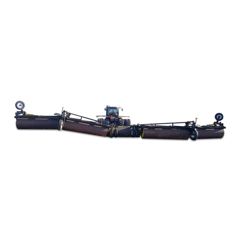
AG SHIELD ReCon 200 Service manual

AG SHIELD
OPERATOR’S HANDBOOK
AND PARTS MANUAL
ReCon 200 pull type
Ag Shield Manufacturing
Box 9, Benito, Manitoba R0L 0C0
phone 800-561-0132 or 204-539-2000
fax 204-539-2130
e-mail address sales@agshield.com
Please visit web site at http\\:www.agshield.com
Printed in Canada - Nov 25, 2002 REV 8A -Part No 113587
Serial no.-1802100 1803700
2” Mechanical gearbox drive


WARRANTY REGISTRATION-ReCon 200 Swath Reconditioner
RETURN TO AG SHIELD MANUFACTURING
BOX 9, BENITO, MB, R0L 0C0
PHONE 800-561-0132 or 204-539-2000 FAX 204-539-2130
e-mail sales @agshield.com
This form must be filled out by the dealer(if applicable) and signed by both the dealer and
customer at the time of delivery, and returned to Ag Shield within 10 days to validate warranty.
Customer ______________________________
Address________________________________
City,___________________________________
Prov.__________ Code___________________
phone(______)__________________________
fax____________________________________
Model and size____ ReCon 200
_____7 ft _____9 ft ____ Double 9 ft.
Delivery Date___________________________
Used for - farm custom haymaking
DEALER INSPECTION REPORT
____Hydraulic Reservoir filled 3” top with reservoir
in working position
____Hydraulic connections all sealed
____Rollers set @1/8” lowest both sides
____Springs set to 14.5” overall
____Tire pressure 18 psi for cushion
Dealer_________________________________
Address________________________________
City,___________________________________
Prov.__________ Code___________________
phone(______)__________________________
fax____________________________________
Model and size_____ ReCon 200
Serial no_______________________________
Delivery Date___________________________
Used for - farm custom haymaking
SAFETY
____All decals installed
____Reflectors clean
____Guards and shields installed
____Review operating and safety instructions
____Retainer pins installed as required
I have thoroughly instructed the customer on the above described equipment, including the content of the Owner’s
Handbook, equipment care, adjustments, safe operation, and applicable warranty policy.
Date___________________________________ Dealer signature_______________________________________
The equipment was complete with all parts in good working order except as noted below. I have received the owner’s
handbook, and I have been thoroughly instructed in the use of it. I have been instructed in the care, adjustments, the
safe operation of the machine, and the applicable warranty policy.
Date___________________________________ Customer signature____________________________________
Except______________________________________________________________________________________


PAGE 5
1.TABLE OF CONTENTS
1. TABLE OF CONTENTS .......................................................................................................5
2. INTRODUCTION AND SIGN-OFF FORM............................................................................7
3. SAFETY .............................................................................................................................8
3.1. SAFETY OVERVIEW...................................................................................................................9
3.2. GENERAL SAFETY.....................................................................................................................9
3.3. MAINTENANCE SAFETY ..........................................................................................................10
3.4. THROWN OBJECTS SAFETY...................................................................................................10
3.5. CHAIN DRIVE SAFETY .............................................................................................................10
3.6. HYDRAULIC SAFETY ...............................................................................................................10
3.7. MECHANICAL GEARBOX DRIVELINE SAFETY...................................................................... 10
3.8. STORAGE SAFETY................................................................................................................... 11
3.9. TRANSPORT SAFETY .............................................................................................................. 11
3.10. REFUELING SAFETY................................................................................................................ 11
3.11. TIRE SAFETY............................................................................................................................ 11
3.12. OPERATING SAFETY ...............................................................................................................11
3.13. SAFETY DECALS...................................................................................................................... 12
4. SETUP FROM SHIPPING MODE ......................................................................................14
4.1. MECHANICAL GEAR DRIVE.....................................................................................................14
5. OPERATIONS ...................................................................................................................15
5.1. RECON 200 ADJUSTMENTS....................................................................................................15
5.1.1. Height of operation-Belleville spring disc washers....................................................................................15
5.1.2. Roller speed.............................................................................................................................................. 15
5.1.3. Timing of Drive Rollers..............................................................................................................................15
5.1.4. Roller adjustment vs crop damage ........................................................................................................... 16
5.1.5. Deflector adjustment.................................................................................................................................16
5.2. OPERATIONS............................................................................................................................16
5.2.1. Lubrication- ...............................................................................................................................................16
5.2.2. Drive chain oiling, all models.....................................................................................................................17
5.3. MECHANICAL GEAR BOX DRIVE ONLY - OPERATIONS....................................................... 18
5.3.1. Hook-Up....................................................................................................................................................18
5.3.2. 540-1000 RPM Changeover .....................................................................................................................18
5.3.3. Clutch F34 Spring Disk Maintenance and Settings...................................................................................19
5.3.4. Spring clutch maintenance and settings...................................................................................................19
5.3.5. Constant velocity (C.V.) shaft.................................................................................................................... 20
5.3.6. Lubrication-Mechanical Gearbox Drive.....................................................................................................20
6. AG SHIELD RECON 200 GEAR DRIVE/ 540-1000 CHANGEOVER.................................21
7. SPECIFICATIONS - RECON 200.......................................................................................22
8. PARTS LIST RECON 200 MECHANICAL GEARBOX DRIVE ..........................................23
8.1. ROLLERS/ MAINFRAME(L.H.) AND WHEEL ASSEMBLY....................................................... 23
8.2. DELFECTORS...........................................................................................................................24
8.3. DECAL LOCATIONS................................................................................................................. 25
8.4. ROLLER DRIVE AND CHAIN OILER ........................................................................................ 26
8.5. DRIVE LINE & HITCH ASSEMBLY ........................................................................................... 28
8.6. DRIVE LINE COMPONENTS..................................................................................................... 30
9. WARRANTY.......................................................................................................................34

PAGE 6

PAGE 7
2.INTRODUCTION AND SIGN-OFF FORM
Congratulations! on your choice of an Ag Shield ReCon 200 forage reconditioner. This equipment has been
designed and manufactured to meet the haying needs of the discerning farmers and custom haymakers.
OPERATOR ORIENTATION - The directions left, right, front and rear, as mentioned throughout this manual, are
as seen from the tractor driver's seat and facing in the normal direction of travel.
Ag Shield follows the general safety standards specified by the American Society of Agricultural Engineers (ASAE) and
the Occupational Safety and Health Administration OSHA). Anyone who will be operating and/or maintaining the Ag
Shield ReCon 200 must read and clearly understand ALL Safety, Operating, and Maintenance information presented
in this manual.
Do not operate or allow anyone else to operate this equipment until such information has been reviewed. Review this
information annually before season start-up. Make these reviews of safety and operation a standard practice for all of
your equipment. An untrained operator is not qualified to operate this machine.
A sign off sheet is provided for your record keeping to show that all personnel who will be working with the equipment
have read and understood the information in the Operators Handbook and have been instructed in the operation of the
equipment.
SIGN-OFF FORM
DATE
OPERATORS SIGNATURE
EMPLOYERS SIGNATURE

8
3.SAFETY
SAFETY ALERT SYMBOL
This Safety Alert symbol means:
ATTENTION! BECOME ALERT!
YOUR SAFETY IS INVOLVED!
The Safety Alert symbol identifies important
safety messages on the Ag Shield ReCon 200
and in the manual. When you see this symbol,
be alert to the possibility of personal injury or
death. Follow the instructions in the safety
message.
Accidents Disable and Kill
3 Big Reasons
Accidents Cost
Accidents Can Be Avoided
SIGNAL WORDS:
Note the use of the signal words DANGER, WARNING
and CAUTION with the safety messages. The
appropriate signal word for each message has been
selected using the following guide-lines:
DANGER -An immediate and specific hazard which
WILL result in severe personal injury or
death if the proper precautions are not
taken.
WARNING - A specific hazard or unsafe practice
which COULD result in severe personal
injury or death if proper precautions are
not taken.
CAUTION - Unsafe practices which COULD result
in personal injury if proper practices are
not taken, or as a reminder of good
safety practices.

9
3.1. SAFETY OVERVIEW
YOU are responsible for the SAFE operation and
maintenance of your Ag Shield ReCon 200. YOU must
ensure that you and anyone else who is going to
operate, maintain or work around the reconditioner be
familiar with the operating and maintenance
procedures and related SAFETY information contained
in this manual. This manual will take you step-by-step
through your working day and alerts you to all good
safety practices that should be adhered to while
operating the reconditioner.
Remember, YOU are the key to safety. Good safety
practices not only protect you but also the people
around you. Make these practices a working part of
your safety program. Be certain that EVERYONE
operating this equipment is familiar with the
recommended operating and maintenance procedures
and follows all the safety precautions. Most accidents
can be prevented. Do not risk injury or death by
ignoring good safety practices.
•Reconditioner owners must give operating instruc-
tions to operators or employees before allowing
them to operate the ReCon 200, and at least
annually thereafter per OSHA regulation 1928.57.
•The most important safety device on this
equipment is a SAFE operator. It is the operator's
responsibility to read and understand ALL Safety
and Operating instructions in the manual and to
follow these. All accidents can be avoided.
•A person who has not read and understood all
operating and safety instructions is not qualified to
operate the machine. An untrained operator
exposes himself and bystanders to possible
serious injury or death.
•Do not modify the equipment in any way.
Unauthorized modification may impair the function
and/or safety and could affect the life of the
equipment.
•Think SAFETY! Work SAFELY!
3.2. GENERAL SAFETY
1. Read and understand the
Operator's Manual and all
safety signs before
operating, maintaining,
adjusting or unplugging the
ReCon 200.
2. Only trained competent persons shall operate the
reconditioner. An untrained operator is not
qualified to operate the machine.
3. Have a first-aid kit
available for use should
the need arise and
know how to use it.
4. Have a fire extinguisher
available for use should
the need arise and know
how to use it.
5. Do not allow riders.
6. Wear appropriate
protective gear. This
list includes but is
not limited to:
•A hard hat
•Protective shoes with
slip resistant soles
•Protective glasses or goggles
•Heavy gloves
•Hearing protection
7. Stop the engine, place all controls in neutral, set
park brake, remove ignition key and wait for all
moving parts to stop before servicing, adjusting,
repairing or unplugging.
8. Review safety related items with all personnel
annually.
2.
4.
6.

10
3.3. MAINTENANCE SAFETY
1. Review the Operators Manual and all safety items
before working with, maintaining or operating the
reconditioner.
2. Stop the tractor engine, place all controls in
neutral, set park brake, remove ignition key, wait
for all moving pads to stop before servicing,
adjusting, repairing or unplugging.
3. Before applying pressure to a hydraulic system,
make sure all components are tight and that steel
lines, hoses and couplings are not damaged.
4. Relieve pressure from hydraulic circuit before
servicing or disconnecting from tractor.
5. Keep hands, feet, clothing and hair away from all
moving and/or rotating pads.
6. Clear the area of bystanders, especially children,
when carrying out any maintenance and repairs or
making any adjustments.
7. Place stands or blocks under the frame before
working beneath the machine.
3.4. THROWN OBJECTS SAFETY
1. Always wear safety goggles when working near or
adjusting conditioner.
2. Never stand or run directly behind rollers when
machine is rotating, as rollers are capable of
throwing obstacles at greater than 30 mph.
3. Shields are provided to reduce thrown debris
hazard, Leave chain guard in place, be sure the
rock guards are in place, inspect chain guard
frequently to ensure protection is in good repair.
3.5. CHAIN DRIVE SAFETY
1. Always keep safety guard in place. You might be
the one who trips and falls into a rotating machine.
2. Never adjust the chain tension, roller spacing,
roller tension, or other items with the machine
running, Always stop the machine before opening
chain cover.
3.6. HYDRAULIC SAFETY
1. Always place all tractor hydraulic controls in neutral
before dismounting.
2. Make sure that all components in the hydraulic
system are kept in good condition and are clean.
3. Replace any worn, cut, abraded, flattened or
crimped hoses and steel lines.
4. Do not attempt any makeshift repairs to the
hydraulic lines, fittings or hoses by using tape,
clamps or cements. The hydraulic system operates
under extremely high-pressure. Such repairs can
fail suddenly and create a hazardous and unsafe
condition.
5. Wear proper hand and eye protection when
searching for a high-pressure hydraulic leak. Use a
piece of wood or cardboard as a backstop instead
of hands to isolate and identify a leak.
6. If injured by a concentrated high-pressure stream
of hydraulic fluid, seek medical attention
immediately. Serious infection or toxic reaction can
develop from hydraulic fluid piercing the skin
surface.
7. Before applying pressure to hydraulic system
make sure that all connections are tight and that all
hoses and fittings are in good condition.
3.7. MECHANICAL GEARBOX
DRIVELINE SAFETY
The operator must obey all safety labels and must
maintain the proper shielding. A high percentage of
driveline injuries occur when safety shielding is missing
or not functioning properly.
1. Do not operate the machine without all driveline,
tractor, and implement shields in place.
2. Before operating the machine be sure drivelines
are attached securely to the tractor and to the
implement.
3. Keep operators and bystanders away from all
moving parts.
4. Shut off tractor engine and remove key before
coming close to the implement or doing any
maintenance

11
5. Drive shafts shielding must be kept in condition
and checked daily to see that it is free spinning on
the inner shaft.
3.8. STORAGE SAFETY
1. Store unit in an area away from human activity.
2. Do not permit children to play on or around the
stored reconditioner.
3. Store in a lower position so persons cannot be
injured or property cannot be damaged by
mechanical failure.
3.9. TRANSPORT SAFETY
1. Read and understand ALL the information in the
Operator's Manual regarding procedures and
SAFETY when operating the ReCon 200 in the
field and/or on the road.
2. Check with local authorities regarding machinery
transport on public roads. Obey all applicable laws
and regulations.
3. Always travel at a safe speed. Use caution when
making corners or meeting traffic.
4. Make sure the SMV (Slow Moving Vehicle)
emblem and all the lights and reflectors that are
required by the local highway and transport
authorities are in place, are clean and can be seen
clearly by all overtaking and oncoming traffic.
Daybreak and dusk are particularly dangerous and
pilot vehicles are recommended.
5. Ensure that the trailer is hitched positively to the
towing vehicle. Always use a safety chain between
the machine and the tractor.
6. Keep to the right and yield the right-of-way to allow
faster traffic to pass. Drive on the road shoulder, if
permitted by law.
7. Always use hazard warning flashers on the ReCon
200 when transporting unless prohibited by law.
3.10. REFUELING SAFETY
1. Handle fuel with care. It is
highly flammable.
2. Do not refuel the machine
while smoking or when near
open flame or Sparks.
3. Stop engine before refueling. Clean up spilled fuel
before restarting engine.
3.11. TIRE SAFETY
1. Failure to follow proper procedures when mounting
a tire on a wheel or rim can produce an explosion,
which may result in serious injury or death.
2. Do not attempt to mount a tire unless you have the
proper equipment and experience to do the job.
3. Have a qualified tire dealer or repair service
perform required tire maintenance.
4. Operate the tires at the pressures, loads, and
speeds suggested by the manufacturer.
3.12. OPERATING SAFETY
1. Read and understand the Operator’s Manual and
all safety signs before using.
2. Stop engine place all controls in neutral, set park
brake, remove ignition key, wait for all moving
parts to stop before servicing, adjusting, repairing
or unplugging.
3. Before conditioning a field, be familiar with all
potential hazards: trees, rocks ditches, gullies,
etc. Plan your route to avoid hazards. Keep
conditioner width in mind when maneuvering to
avoid obstacles.
4. Keep hands, feet, hair and clothing away from all
moving and/or rotating parts.
5. Keep all shields and guards in place when
operating.
6. Do not allow riders on the ReCon 200 or tractor
during operation or transporting.
7. Clear the area of all bystanders, especially
children, before starting.
8. Stay away from machine when folding deflectors.
Keep others away.
9. Before applying pressure to the hydraulic system,
make sure all components are tight and that steel
lines, hoses and couplings are not damaged.
10. Review safety instructions annually

12
3.13. SAFETY DECALS
Become familiar with these decals and the hazards they are marking.
part #113522 part #113524
1.
part # 113552

13
Become familiar with these decals and the hazards they are marking.
part # 113523 part # 113525
part # 113526

14
4.Setup from Shipping Mode
4.1. MECHANICAL GEAR DRIVE
**Refer to section 7, SPECIFICATIONS - RECON 200,
page 22 for correct requirements for the model and
size of your ReCon 200.
The ReCon 200 roller unit has been run and rollers
timed at the factory.
The driveline was tested for output, although not all
components together.
Items required or preferred for setup
1. Tractor with front end loader or forklift
2. Tractor with hydraulic system to raise and
lower, machine, and 1000 or 540 PTO as
required.
3. Hand tools
4. Source of air to inflate tires to 18 psi and
pressure gauge
Procedure
1. Inflate tires to 18 psi only (depending on model
and size of your machine). This pressure will
allow the tires side wall to flex over bumps in
the field, and yet is enough pressure to allow
long distance travel at 100 km/h (60 mph).
2. Place ReCon 200 in area where you can use
front end loader at 15ft height
3. Remove the one inch pin holding 2 arms
320205 & 320206 to deflector.
4. Cut wires and metal banding that hold plastic
deflectors (320269 & 320270) onto chassis
and set aside the deflectors.
5. Cut wires and metal banding that hold top all
metal deflector (320236) onto chassis. Loosen
jack(also secures deflector) and set deflector
and jack aside
6. Remove toolbox & obtain these instructions
7. Cut straps securing A-front forward hitch. With
a partner or hoist set aside. Cut zip ties and
remove the two pieces of PTO shaft. Remove
yellow hose/light bar and set aside. Hook
chain to main frame hitch. Use the loader to
back up and pull the mainframe over to leave
unit in field ready position.
8. Install A-front forward hitch onto mainframe
using the 5/8”x2” bolts and 5/8” nylok nuts and
torque to 160+ lb.-ft. Install the hitch jack onto
the hitch- assembly so that it points in the
same direction as the four mounting holes.
9. Hook up the farm tractor to the draw bar and
adjust hitch to provide 14”-16” rearward from
tip of PTO shaft to center of draw pin hole.
10. Attach forward drive shaft with smaller
overrunning clutch towards rear of machine
and CV joint towards front of machine(to
tractor)
11. Attach unit driveline to tractor using the quick-
connect coupler.
12. Install right hand light mount by inserting tube
into socket on top of rear corner, and
tightening the t-bolt.
13. Install right left hand light into bracket using
6mm nuts.
14. Remove plug from lift cylinder Attach the two
¼” hoses to the lift cylinder. Clean and plug
hydraulic couplers into tractor, and raise unit
slightly until bottom of rollers is about 25 cm
(10 inches) above ground.
15. Refer to 8.1ROLLERS/ MAINFRAME(L.H.)
and wheel ASSEMBLY page 23. Install the
tool box on the top and near the forward edge
of the deck (on left hand side) Use two ¼NC x
1’ bolts with washers and self locking nuts.
16. Fill the chain oiler reservoir (black cap) with 5
liter (1.4 US Gal) of hydraulic oil (JD Hy Gard
or equivalent) and replace cap. Remove the
retaining clip and flip the guard up to the front
of the machine, open the oil valve. Be sure to
shut valve off when testing is complete, as
reservoir will drain onto ground.
17. Clear the area of all bystanders, and be sure
no tools or items are near the rollers. Start the
PTO slowly, observe that the rollers turn,
18. With PTO running raise unit to top, top roller
should lift clear of bottom roller. Operate at
full-recommended speed for 1 minute, observe
chain runs smoothly. Stop machine and
observe that oil began to flow to the chain
oiling brush while the machine was running.
19. Remove 1” OD x 3 5/8”pin on ram end of
deflector cylinder and swing center link out
towards rear of machine. Reattach link (tab
end) to deflector cylinder using 1” OD x 3 5/8”.
Link is marked up/down and long end of link
should be nearest unit. Attach the two ¼”
hoses to the lift cylinder.
20. Using two 1” OD x 5” long pins, install left
deflector. The pin head notch must straddle
the ReCon frame to stop the pin from turning.
Use the cotter pins supplied to retain the hinge
pins. Install the right deflector and cotter pins.
21. Install the top deflector through 2 oblong holes
in side frame above and to the rear of the
rollers. Retain with the bushing and ¼” bolt
provided.
22. Grease the 4 grease nipples on deflector
pivots; the four on the front of the main lift
rockshaft and one on each side on the upper
roller pivots. Refer to 5.2.1Lubrication-, page
16.
23. Refer to section 8.2 Deflectors page 25. Install
arms (320201,320205,320206) as marked.

15
5. OPERATIONS
DANGER
WATCH FOR THROWN OBJECTS
WHENEVER MACHINE IS RUNNING
5.1. RECON 200 ADJUSTMENTS
The tires have been oversized for maximum flotation;
factory setting of tire pressure is 17-19 psi to take
advantage of suspension in tire side wall.
5.1.1. Height of operation-Belleville spring
disc washers
Proper operating height is the maximum at which the
rollers do an excellent job of picking up the swath,
usually 8 cm (3”) or more between bottom of roller lug
and the ground. You will have excessive maintenance
if the rollers are continually contacting the ground. All
pull type models have Belleville spring disc washers on
the lift cylinder to give smooth ride at all operating
heights
Set the stroke adjustment on the hydraulic cylinder to
the normal operating position. This setting will
eliminate the possibility of the rollers being run into the
ground on an operator over travel.
Use highest settings to reduce contact with knobby
stones and pick up or throw fewer fist-sized stones.
Chain Tension
Refer to “A” Ag Shield ReCon 200 drawing, pg. 20
The main drive chain is kept in correct tension at all
times with a compression spring tightener. Continue to
increase chain tension until the spring holding cup is
within 13mm (1/2”) of the spring adapter wldt.(sprocket
mount), that is, only 1/2” of spring is visible. This
setting allows the idler sprocket to take up extra chain
length as upper roller floats without allowing rollers to
become out of time.
Spring Tension
The upper roller springs should be tightened until the
overall extreme spring measurement is 37cm (14.5”).
This tension will to keep rollers from moving up
excessively even in heavy crops and will allow passage
of a 8 cm (3”) stone or other hard object with out
damage to rollers.
Upper Roller Lift
Refer to “B” on drawing following this section.
When the ReCon 200 frame is raised to highest
hydraulic height, the upper roller should be lifted to
have approximately 3cm (1 ¼ ”) of gap between the
lugs of the rollers. Chain may have links removed or
added to achieve this setting. Use the lower of two
holes in the lever on the rockshaft and 30 rollers plus 2
joiners as a starting point. For your convenience, units
have a hole in side plate to allow chain joiner to feed
from the inside of end plate when putting link on pivot
plate end.
Clearing a Wad
On PTO mechanical drive models, a wad that stops
the rollers from turning causes the slip clutches to slip.
To get going again, disengage the PTO, raise the
machine to highest height (to raise the upper roller),
and engage PTO to start rollers. If roller fails to start on
2 attempts, place PTO in OFF position, turn off the
motor, set the park brake, and walk to rear of machine
and lift on lugs of bottom roller to turn wad back out
and clear the rollers. A 12-15” crescent wrench can
give the operator additional mechanical advantage.
For operation in hemp or wadded swath conditions, an
optional 30” roller turning "wrench" is available to assist
in reversing rollers. This wrench (part # 320330) also
scraps clay from between the lugs on the rollers.
5.1.2. Roller speed
The ReCon 200 is designed to have high roller
speed to throw material when combining swaths
and to lesser degree inverting swaths. If you are
not combining or inverting, the life of the drive
chain will be more than doubled by running at 75%
of standard input speeds as shown in table below.
Nominal pto
input speed
Actual PTO speed
Combining or
inverting swathes
Fluffing, pick up
put down swath
behind machine
540
540 rpm
400 rpm
1000
850 rpm
650 rpm
If the swaths are extra heavy, this reduced speed will
somewhat reduce capacity.
5.1.3. Timing of Drive Rollers
Refer to “C” on drawing following this section.
It is essential that drive rollers be kept in proper timing
and adjustment at all times to avoid damage to drive
components.

16
Timing is accomplished by setting the top roller rotation
to mesh with the bottom roller using the timing notches
ground into the upper roller shaft. At the factory, the
key way on the lower roller shaft is aligned at the
1:30 position with notches ground into the upper
shaft at the 7:30 position. A new chain should align
exactly in this position. A well-used chain will align in a
slightly different position as caused by longer chain
between roller sprockets. Refer to 6 AG SHIELD
RECON 200 GEAR DRIVE/ 540-1000 CHANGEOVER
page 21.
Set the top roller to have 3.3mm (1/8”) clearance
between lug and body of bottom roller, which is the
normal lowest setting with the machine height in a low
enough position that the 50 chains are not lifting the
upper roller. Rotate the rollers by hand to align the key
way of lower roller at 1:30 with notches ground into the
end shaft of upper roller at 7:30.
If this cannot be done, loosen the 80 chain drive at
spring tensioner, and jump chain over sprocket teeth
on lower roller until timing is correct. If timing cannot be
corrected with above procedure, then chain stretch has
caused upper roller to rotate counter clockwise (as
viewed from right side) in drawing and 3/4”
measurement will be decreased.
The chain should be replaced when 12 links of chain
exceeds 314mm (12 3/8”), an increase of 3% or 3/8”
from new length, in the opinion of some chain
manufacturers much sooner.
On serial numbers 1803113, top roller lug is 2.5mm
(1/16”) from barrel of bottom roller, and the spacing
from rear side of lug on bottom roller to front of lug of
top roller is 22mm (7/8”).
5.1.4. Roller adjustment vs crop damage
Refer to “D”. Ag Shield ReCon 200 drawing, pg. 20
Rollers are factory set to have 1/8” or less between the
lug of top roller and the round barrel of lower roller
when the roller Quik Set (part # 320230) is at minimum
thickness. This setting will give a very aggressive
crimping action required for fastest dry down. As the
forage becomes drier in swath, it may be desirable to
move the rollers further apart. The rollers can be
quickly raised 8mm (5/16”) to reduce crimp, or 16mm
(5/8”) to leave slight overlap of lugs on rollers, or
24mm (15/16”) to have only a fluffing action on the
swath.
If increasing the gap between the rollers does not
reduce crop damage to an acceptable level, consider
reducing the roller speed, by reducing PTO speed as
low as 60% of normal rpm.
5.1.5. Deflector adjustment
The adjustment of both top and side deflectors is
critical to obtaining desired results. Both of these
adjustments are in turn modified by changes in
forward speed. A small change frequently causes
dramatic changes in swath shape, position, and
degree of inversion.
Refer to “E” on drawing following this section.
The top deflector changes the place of contact of the
swath on the side deflector. Use lower setting in high
(cross) wind conditions to keep material from
scattering excessively. Use highest setting to raise a
swath up and drop down on same location. Use any
setting to alter the degree of inversion of swath by
directing to different position on rear deflectors. In
hemp, a low setting will be preferred to keep heavy
stocks from scattering.
Side deflectors have a high degree of adjustment to
give maximum flexibility in machine usage. The factory
setting will allow swaths to be moved to left or right,
inverted, or the combining of two cuts into one swath,
while the 2nd deflector provides wind protection for the
process. Swaths may be shaped into a high narrow
configuration by causing material to tumble off of the
end of deflectors, or left in original width by setting side
deflectors wide enough to avoid contact.
When operating in high crosswind conditions, consider
changing side deflector at each end of field to throw
primarily down wind.
If 2 conditioning passes (in grasses or hemp) are
anticipated, leave the swath wider during first pass,
narrowing during second, If bleaching of green color is
primary concern, consider more side deflector action to
invert and mix swath.
Swaths may be combined with your ReCon 200 by
driving one direction and throwing material to the side,
and returning on next swath deflecting second swath
on or beside the first. Two 12 ft swaths may be
combined using standard side deflectors, two 14 may
be combined into a single 28ft swath by using optional
extensions (part# 320301).
5.2. OPERATIONS
5.2.1. Lubrication-
Grease using standard high quality grease according
to the following table. Do not over grease wheel and
roller bearings to the point where seals are damaged
or pushed out.

17
decals mark zerk
locations
MAINFRAME/ROLLER DRIVE
LOCATION
PERIOD
# OF ZERKS
Main height rock
shaft
10hr daily
4 along top
Deflector inner
hinges
10hr daily
2 each side
Height cylinder
adjustment
10hr daily
1 on casting
Upper roller
pivots
10hr-daily
1 each side
Wheel bearings
Weekly +
1 each side
Main roller
bearings
120 hours
3 shot per
bearing
2 each side
do not over
grease
Chain tightener
320872
10hr/daily
1 on wldt
Spring adapter
320876
10hr/daily
1 on wldt
DRIVELINE
Decal
below
LOCATION
PERIO
D
# OF
PUMP
S
# OF
ZERKS
CV Shaft
Assembly:
A
Center body
(C.V. joint)
8 hr/
daily
10-30
1 ea. side
of joint
B
Cross
journals
8 hr/
daily
4-8
1 ea. yoke
C
Outer tubing
16 hrs
daily
1-2
1 ea tube
D
Inner tubing
16 hrs
daily
1-2
1 ea tube
E
Shaft inner
16 hr/
daily
4-8
No zerk
Apply to
shafts
F
Quick
connect
yoke
40 hr/
weekly
4-8 to
inside
spline
s
No zerk
Apply to
splines
Overrunning
clutch
40 hr/
weekly
1
1 on clutch
assembly
U-joint
(side drive
shaft
8
hr/daily
2-4 as
req’
1 at
gearbox
Pillow
Block*2*
Annual
4-8 as
req’
1 on ea.
pillow
block
Refer to section 8.6 DRIVE LINE COMPONENTS
page 30 for additional information on lubrication points
of driveline.
5.2.2. Drive chain oiling, all models
Your ReCon 200 has a 5 liter (1.4gal) reservoir built
into the frame. The reservoir will empty during normal
use in less than 10 hours of operation. Refill through
the black pipe cap protruding through the top of
machine near the drive chain end. The drive chain
requires continuous lubrication using transmission
hydraulic oil or 30W motor oil. Oil that is too high a
viscosity will not penetrate between the side plates to
the pivot pin location. Sticky chain lubrication oils will
lubricate the outside of roller but not get between side
plates.
The ReCon 200 mechanical drive has a valve on a
hose that must be turned on before chain drive begins
and off when not in operation for more than 10
minutes.
To maximize the life of the drive chain, consider
removing chain daily to soak overnight or having 2
chains to run on alternating days.
The chain should be replaced when 12 links of chain
exceeds 314mm (12 3/8”), an increase of 3% or 3/8”
from new length. Replace with highest quality chain
available (prefer Ag Shield part # 114206 for Tsubaki
long life 80 chain for longest life in comparative tests in
this application)

18
5.3. MECHANICAL GEAR BOX
DRIVE ONLY - OPERATIONS
5.3.1. Hook-Up
Length
Adjust the tractor hitch length to provide 14”-16”
rearward from tip of PTO shaft to center of draw pin
hole.
Attachment
Lubricate tractor PTO splines and quick disconnect
yoke with grease to reduce wear on splines. Twist
locking collar and slide quick connect yoke onto PTO
shaft. Be sure the driveline is properly attached and all
bolts and setscrews are tight on the implement input
shaft and on the tractor PTO shaft. Raise jack to
storage position.
Shielding
Be sure the shielding is not damaged and rotates
freely on the driveline.
Working angle
Constant velocity joints can operate up to 80 degrees
for short periods.(i.e. during turns).
Storage
When not in use, cover to protect the driveline from the
weather. When removed from the machine, store both
half shafts together to prevent damage. Check all
components for proper function and lubrication before
use.
5.3.2. 540-1000 RPM Changeover
The ReCon 200 is designed to have high roller
speed to throw material when combining swaths
and to lesser degree inverting swaths. If you are
not combining or inverting, the life of the drive
chain will be more than doubled by running at 75%
of standard input speeds as shown in table below.
Nominal pto
input speed
Actual PTO speed
Combining or
inverting swathes
Fluffing, pick up
put down swath
behind machine
540
540 rpm
400 rpm
1000
850 rpm
650 rpm
The RECON 200 gearbox PTO drive is designed for
conversion from standard 540 input RPM to 1000
RPM. For maximum driveline life, the 540 rpm shaft
speed is recommended.
Optional # 320473 - 540-1000 RPM Changeover kit
These optional parts include:
1- 114260 drive sprocket (80Q18)
1- 114249 idler sprocket (80x12T ¾” bore
1- 100903 hex hd bolt 3/4 x 4
1- 102128 nylok nut 3/4 gr. 5 pltd.
2- 101118 ¾” washers (1/8” thick)
1- 320471 spacer, ¼”
1- 320472-spacer 1/2”
for temporary change
1-111311 PTO adapter 1 3/8 21 female x 1 3/8 6
male(540 spline)
OR
For more permanent change-
Optional #320474
These optional parts include:
1- 320473 540-1000 RPM Changeover kit
1- 111693 Yoke 1 3/8 21 female(1000 spline) for end
of drive shaft
Refer to section 6 AG SHIELD RECON 200 GEAR
DRIVE/ 540-1000 CHANGEOVER, page 21 and follow
this sequence:
1. Lower machine towards field position slowly
until the 50 chains that lift the upper roller are
loose.
2. Remove the chain guard.
3. Observe the that alignment of the timing marks
on top and bottom roller shafts is the same as
the recommended on the diagram in section 6
AG SHIELD RECON 200 GEAR DRIVE/ 540-
1000 CHANGEOVER page 21. If not mark for
speed of reassembly and timing.
4. Raise the machine to highest setting for
convenience during changeover procedures.
5. Block machine at this height for safe working
conditions. .
6. Ensure PTO disengaged, parking brake is
engaged, tractor is shut off, and key removed.
7. Loosen 80 chain at spring tightener until 1”or
more slack. Remove cotter keys from joiner
link and remove chain.
8. Remove 4 chain rollers until 82 rollers remain.
Use the half link to reconnect. Set chain aside.

19
L
L
9. Remove bushing bolts and bushing from top
sprocket (80Q30) and remove top sprocket
from the 1 3/8” shaft
10. Install idler sprocket (part #114249) on raised
tabs (J) directly below area of top shaft using
¾”bolt and nut. Use spacers and washers
provided to align sprocket with the chain travel
over other sprockets.
11. Install 80Q18 sprocket on shaft using same
bushing as the 30 tooth sprocket. Align slightly
inside the line of the bottom sprockets and
tighten bushing bolts. The sprocket should pull
into proper line as 3 bolts are tightened. Final
torque on the 3 bolts should be 25-30 lb ft
12. Remove blocking and lower machine to
ensure rollers are at correct timing marks
(notches in line).
13. Reinstall 80 chain (length-82 rollers) around all
drive and idler sprockets (see diagram pg 22, )
and tighten chain to proper tension. At this
point adjustment may be required to one or
more sprockets to bring all in line, so chain
may have to be loosened Be sure that all
sprockets are aligned and that timing notches
are aligned. Retighten chain to proper working
tension as per 5.1-RECON 200
ADJUSTMENTS page 15
14. Start the tractor and engage PTO at low
engine RPM. If the rollers are not clashing,
slowly raise the ReCon 200 to the top of travel.
This check is necessary to ensure timing is
correct even when the roller is raised up on a
wad during field operation.
15. Reinstall the chain guard.
16. If this is a temporary changeover, remove
driveline from tractor stub, change output shaft
of tractor to 1000 rpm, install the shaft adapter
(part # 111311), and reconnect the driveline.
Use only bolt tightening adapters.
17. Lengthen drawbar to again provide 14”-16”
rearward distance from tip of PTO shaft to
center of draw pin hole.
18. If this is intended as a more permanent
changeover install yoke (part# 111693) on
front of driveline for optimum future operation.
19. Happy haymaking!!
5.3.3. Clutch F34 Spring Disk Maintenance
and Settings
Torque Setting Thickness Height (L)
5.3.4. Spring clutch maintenance and
settings
Annual maintenance of your clutch is required to
ensure that the unit has not rusted and seized in the
off-season, effectively eliminating the clutch protection
of components.
Refer to “F” in section 6 AG SHIELD RECON 200
GEAR DRIVE/ 540-1000 CHANGEOVER page 21.
1. Park the ReCon so that the discharge of ReCon is
clear for 50 yards behind the machine.
2. Shut off tractor engine, set the park brake,
disengage the PTO lever, and remove the key.
3. Loosen the 8 bolts sufficiently (approximately 1 full
turn) using a 17mm wrench. This will allow the
friction plates to slip when machine rollers are
jammed to simulate a wad or blockage situation.
4. Kneel down in front of one corner of machine, and
pull the rock guard aside. Place a sound block of
wood (a piece of 2”X4” approx.8 inches. long
works well) between upper and lower roller lugs
with the 8” side parallel to the long axis of the
rollers. Slightly turn the rollers to hold the block
between 2 lugs
5. Observe that no person or being is in the possible
discharge of the block. Although there is NO
incidence of this jamming device failing to stay in
position, better safe than sorry.
6. Start tractor and carefully engage PTO, watching
that the jamming device is working properly to stop
rollers.
Nm
In.lb
mm
in
mm
in
800
7080
3.50
0.14”
18.0
0.71”
L= .71” or
18 mm

20
7. Friction type torque limiter should slip on its own
hub. This ‘burning the clutch ‘ removes rust from
the friction plates and prevents damage that could
occur should the friction plates become seized and
not operate properly.
8. DISENGAGE PTO (AFTER APPROX 5 SEC),
then shut off tractor, and remove key. Visually
inspect the condition of all components, and
service or replace as necessary.
9. Remove object used to jam rollers.
10. Retighten clutch bolts to specifications, ensuring
that proper working length of spring is achieved
and that this distance is constant for all
springs.(see chart)
Spring clutch tension settings
Setting the clutch is critical to correct function of the
unit. Adjustment tighter than these settings will result
in damage to other components when roller blockage
occurs. Improperly tight settings of the springs will void
warranty.
Using the 6 mm wire spring supplied, the following
chart gives correct spring tension
RPM
WORKING
LENGTH-
(INCHES)
WORKING
LENGTH
In MM
1000
1.122
28.5
540
1.102
27.5
5.3.5. Constant velocity (C.V.) shaft
1. The manufacturer recommends proper
lubrication and inspection intervals of C.V.
components.
2. Become familiar with the limits of the C.V.
shaft assembly and components
3. Working angle of constant velocity joints can
operate up to 80 degrees for short periods
required to turn 90 or 180 degree corners.
4. Refer to 5.3.1,Hook-Up, page 18 for
information on working angle, attachment, and
storage of C.V. shaft and driveline
components.
5.3.6. Lubrication-Mechanical Gearbox
Drive
Frequent lubrication is required to maintain superior
performance and minimal wear of parts. Grease the
driveline parts after the number of hours of use as
shown on the chart.
1. After long periods of non-use, lubricate and check
the function of every driveline component before
operating machine.
2. Grease all universal joints on shaft.
3. Wipe any excess grease off clutch assembly and
other driveline components.
4. Check oil level in gearbox and add oil if necessary.
5. Ensure proper operation of friction-type torque
limiter.
6. Lubricate tractor PTO splines and quick disconnect
yoke with grease to reduce wear on splines
GEARBOX
1. Remove the lower of the two oil level indicator
plugs on side of gearbox.
2. If oil begins to drain from the port then the
3. oil level is satisfactory.
4. To add oil, remove fill plug located on top of
gearbox. Always use 80-90W gear oil
5. Fill until oil begins to drain from level indicator port
on side of gearbox.
Replace side and top plugs and tighten
DRAIN AND REFILL GEARBOX AT THE BEGINNING
OF EACH SEASON
1. Run machine to warm the oil before draining.
2. Raise the machine to a point where the gearbox is
level (allows for proper drainage) and block
machine for safety.
3. Observe all safe working conditions while
performing maintenance. Refer to 3.3
MAINTENANCE SAFETY, page 10.
4. Access drain plug through hole in gearbox mount
plate from front and underside of machine Remove
drain port plug located on bottom of gearbox using
a 5/16”allen wrench.
5. Drain oil into container; replace and tighten drain
plug.
6. Remove oil indicator plug on side of gearbox.
Remove fill plug located on top of gearbox. Refill
gearbox to operating level (oil level at bottom edge
of check port). Always use 80-90W gear oil.
7. Replace side and top plugs and tighten.
8. Remove safety blocking, start and run unit to
check for leaks.
GEARBOX
PERIOD
FILL CAPACITY
2050
ANNUAL
1.0 LITER/ 35oz.
2070
ANNUAL
1.4 LITRE/ 49oz.
2070 with side
arm
ANNUAL
1.6 LITRE/ 60oz.
Table of contents
Other AG SHIELD Farm Equipment manuals