AGI NECO 04HC24NGV Guide

040714 R01 1
Axial Fan Heater
Assembly, Operations, and Parts Manual
Part Number: 040714 R01
Revised: 2017-12-22
INSTALLATION AND WIRING MUST
BE IN ACCORDANCE WITH CEC,
NEC, AND LOCAL ELECTRICAL
CODES
Read this manual before using product. Failure to
follow instructions and safety precautions can
result in serious injury, death, or property
damage. Keep manual for future reference.

2
Nebraska Engineering Company (NECO) Overview ---
Since 1959, NECO equipment has been proudly designed, manufactured, and supported for
customers here in the USA and around the world. With proper operation and maintenance,
the equipment will provide years of safe and dependable service. NECO is continually testing
and improving our products in order to provide you with the safest, most ef cient, and most
economical grain handling & grain conditioning equipment available. We welcome your questions
or comments and look forward to a continued relationship, ultimately saving you valuable time and
reducing your workload.
About this manual ---
• This manual is provided to help ensure the safety of the equipment
operator, as well as others who come into contact with the equipment.
• Keep a copy of this manual in a safe place for future reference.
• Failure to read, understand, and follow the instructions within
this manual constitute a misuse of the equipment and can affect
personnel safety and the product warranty.
• Additional copies can be viewed or printed from the NECO
website www.necousa.com or contact your local dealer for
assistance.
• Language translations of this manual are made as accurately as
possible. If translation differences do occur, the English text will
prevail.
READ
and
UNDERSTAND
Watch for this symbol - it means DANGER or CAUTION !!
Be alert to the possibility of serious injury or death.
• This symbol is used to call your attention to
instructions concerning personal safety.
• It is your responsibility as an owner, operator,
or supervisor to know what hazards exist and
to make this information known to all persons
working with the equipment or who are in the
area.
Become Alert !!
Product Changes & Improvements ---
• NECO reserves the right to make changes or improvements to its products
without incurring any obligation with respect to previously manufactured products.

3
For a period of one(1) year after shipment of goods by the Buyer to the Buyer’s
customer, NECO will supply, free of charge, FOB per NECO’s factory located
in Omaha, Nebraska, replacement parts for any parts that NECO identifi es to be
defective due to workmanship or material.
• This limited warranty does not extend to parts that wear due to normal operation and need to be
replaced periodically.
• Goods not manufactured by NECO carry only their manufacturer’s warranty.
• This undertaking is in lieu of all other warranties, expressed or implied, including merchantability
and tness for a particular purpose.
• You must obtain a “Return Authority” form from NECO prior to returning any defective goods.
Those defective goods must be returned, freight-prepaid, to the NECO factory in Omaha,
Nebraska. See the back cover of this manual for complete address information.
• NECO reserves the right to make changes or improvements to products and goods without
incurring any obligation with respect to previously manufactured products.
• Failure to follow the instructions contained in this manual, as well as the existence of any of the
conditions listed below, will cause this Limited Warranty to be null and void:
1. Improper assembly.
2. Improper installation, including power and wiring.
3. Unauthorized alteration of the product or components therein.
4. Operation of the unit when repairs are needed.
5. Use of unauthorized parts.
6. Operation by children or uninstructed personnel.
7. Processing of materials that are abrasive, that do not ow freely,
or that are otherwise unsuited for processing in farm equipment.
8. Misuse of the equipment or any of its components.
9. Damage due to negligence, abuse, or accidents.
LIMITATION OF LIABILITY
• Buyer agrees that in no event shall NECO have liability for direct damages in excess of the
contract price of the goods for which the claim is made.
• Buyer further agrees that in no event shall NECO have liability for loss of use, loss of pro ts, or
for any indirect, incidental, or consequential damages on any claim of any kind.
***** LIMITED WARRANTY *****

4
Table of Contents
GENERAL STATEMENTS................................................................................................................ 2
WARRANTY ..................................................................................................................................... 3
SAFETY............................................................................................................................................ 5
OPERATOR QUALIFICATIONS ............................................................................................ 5
OPERATING PROCEDURES ............................................................................................... 5
POWER LOCK OUT.............................................................................................................. 6
MACHINE INSPECTION ....................................................................................................... 6
WORK AREA SAFETY .......................................................................................................... 6
AVOID STRUCTURAL DAMAGE .......................................................................................... 7
AVOID FIRE, EXPLOSION, AND ASPHYXIATION HAZARDS ............................................. 7
INSTALLATION DATA AND MOUNTING PAD ................................................................................. 8
INSTALLATION...................................................................................................................... 9
GROUNDING ...................................................................................................................... 10
FUEL SUPPLY..................................................................................................................... 10
PROPANE ...................................................................................................................... 10
NATURAL GAS .............................................................................................................. 13
COMPONENT IDENTIFICATION AND FUNCTION....................................................................... 14
SETTING THE DRYING TEMPERATURE ..................................................................................... 15
PRE-START CHECK...................................................................................................................... 16
INITIAL START-UP USING PROPANE .......................................................................................... 16
HEATER OPERATIONS................................................................................................................. 16
RECOMMENDED DRYING TEMPERATURES ............................................................................. 19
WIRING DIAGRAM NOTICE.......................................................................................................... 20
DRYING PRECAUTIONS............................................................................................................... 21
JOHNSON CONTROLS SERIES V50 FOR SELF-OPERATED MODULATING VALVES............. 22
TROUBLESHOOTING GUIDE....................................................................................................... 24
MAINTENANCE ............................................................................................................................. 28
REPLACEMENT PARTS................................................................................................................ 29

5
OPERATOR QUALIFICATIONS
Operation of this farm equipment shall be limited to competent and experienced
persons. In addition, anyone who will operate or work around power equipment
must use good common sense. In order to be qualied, operator must also know
and meet all other requirements, such as:
1. Some regulations specify that no one under the age of 16 may operate power machin-
ery. This includes farm equipment, It is your responsiblity to know what these regula-
tions are in your own area or situation.
2. Current OSHA regulations state in part: "At the time of intial assignment and at least
annually thereafter, the employer shall instruct every employee in the safe operation
and servicing of all equipment with which the employee is, or will be involved."*
3. Unqualied persons are to stay out of the work area. The "Work Area" is dened as the
area surrounding the grain handling equipment.
4. A person who has not read and understood all operation and safety instructions is NOT
qualied to operate the machine.
* Federal Occupational Safety & Health Standards for Agriculture Subpart D,
Section 1928.57 (a) (6).
OPERATING PROCEDURES
During the operation of your farm equipment, one person shall be designated to monitor the
machinery. It is also good practice for all qualied persons involved to visually inspect the
equipment periodically during any actual operation. You should be alert for any unusual vi-
brations, noises, and loosening of any fasteners.
1. Observe work area restrictions.
2. Keep all safety shields and devices in place.
3. Make certain everyone is safely clear before operating or
moving farm equipment.
4. Keep hands, feet, and loose clothing away from moving parts.
5. Always disconnect power before servicing equipment!
CAUTION:
NOTE: Foreign customers are responsible for knowing and applying their local safety regulations.
SAFETY

6
POWER LOCK OUT
It is essential to inspect your fan and heater before turning on the power. Know how to shut
down the fan anf heater power in an emergency! Prior to any servicing or adjusting of your
equipment, make certain to shut down the power and lock it out.
1. Electric motors and controls shall be installed by a qualied electrician.
Installation must meet standards set by the National Electrical Code and all local and state
codes.
2. Always disconnect and lock out power before servicing the fan and heater.
3. Reset and motor starting controls must be located so that the operator has a full view of the
entire operation. Always keep children away from unit!
4. Make certain that all fan guards are reinstalled after servicing.
A main power disconnect switch capable of being locked only in the OFF position shall be in-
stalled. This shall be locked out whenever the equipment is being serviced.
After delivery of your new fan/heater and/or completion of assembly and before each use, in-
spection of the equipment is mandatory. This inspection should include but not be limited to:
1. Check to see that all guards listed in the assembly instructions are secured
in place and are functional.
2. Check that all fasteners are tight.
3. Before starting fan, be sure that fan interior and inlet is clear of any debris.
4. Make certain that impeller rotates freely.
5. Open roof hatches before use.
6. Inspect all electrical and gas connections. Check for leaks with soapy water.
7. Are all safety decals clean and readable?
8. Before starting heater read start-up procedures.
MACHINE INSPECTION
People not involved in the operation should not be allowed into the work area.
It shall be the duty of all operators to see that children and/or any other unqualied per-
sons stay out of the work area. Trespassing into the work area by anyone not involved in the
actual operation, or trespassing into a hazardous area by anyone, shall result in an immediate
shut down by the operator.
It is highly recommended to wear hearing protection when standing near operating fan.
Prior to start up and during operation, it shall be the responsibility of all operators to see
that the work area is clear. It must be clean and free of any debris and misplaced tools which
could cause accidental tripping and/or falling.
WORK AREA SAFETY

7
FAILURE TO HEED THESE INSTRUCTIONS
CAN RESULT IN PERSONAL INJURY OR DEATH!
BE EXTREMELY CAREFUL OF THE HIGH VOLTAGE
PRODUCED BY THE IGNITION UNIT.
NOTE: IF YOU EXPERIENCE PROBLEMS WITH YOUR HEATER, CONTACT
YOUR DEALER FIRST. IF THEY ARE UNABLE TO HELP, CALL THE SERVICE MANAGER AT
NECO. THE PHONE NUMBER IS 1-800-367-6208 OR (402) 453-6912.
AVOID FIRE, EXPLOSION, AND ASPHYXIATION HAZARDS
NECO Heaters are designed for drying crop output in grain bins. They provide heated air via
grain bin plenums (found underneath full-oor bins) or via in-oor ductwork.
Consult the NECO factory before attempting to use heaters for EZEE-DRY applications.
Never use NECO heaters to heat buildings, sheds, barns, etc. because of hazards posed by
the ame and by the output of carbon monoxide.
Never install or use NECO heaters where a high concentration of grain dust or ammable
liquids or vapors exists because explosions could result. A common grain bin lled with grain
such as shelled corn, beans, or wheat is not considered an explosive (volitile) environment. A
metal or concrete silo lled with nely milled grain dust, however, does consitute an explosive
environment.
Never allow anyone to enter the grain bin when a fan and heater is operating! Gasses given off
by the burner (including carbon monoxide and carbon dioxide) could cause death.
When installing the heater make sure that the plenum area is clean of any ammable debris
especially within 10 ft. of the heater transition entrance. At the end of each season clean the
transition, heater entrance, and plenum. Good housekeeping is essential to prevent bin res.
Before loading the bin with grain, make certain that the plenum oor or ductwork is not dam-
aged or plugged. Also, check the operation of the aeration fan to make certain that the roof
vents are unobstructed.
Avoid Structural Damage to your Bin
Ensure that all roof vents are open and unobstructed.
Ensure adequate ventilation. NECO recommends a minimum of 1 square foot (929
cm2) of vent area per every 1000 cfm (21 m3/min) fan air input.
Make certain that all fans are installed for positive pressure aeration (push system).
Roof exhausters should be interlocked with aeration fans so that roof exhausters can
run only when the aeration fans are running.
Never operate your bin aeration system when icing of the roof vent is possible. Roof
vent icing can occur when the ambient air temperature is below 35° F (2° C) and
the relative humidity of the air is 90% or greater. Check with your local weather
bureau.
AVOID STRUCTURAL DAMAGE

8
Fan
Heater
HEATER
SINGLE HEATING UNIT
TWO HEATING UNITS
BURNER CONTROL
FOR SECOND
(THERMOSTAT/
Unload System
HUMIDISTAT)
Bin
Heater
Fan
Unloading
System
Bin
1 1/2 SHEETS MIN.
INSTALLATION DATA
and MOUNTING PAD
When installing your heater unit, plan the sys-
tem such that proper consideration is given to:
1. For even heat distribution. Install the heater
inline with the unloading auger (see Figure 1).
For more than one heating unit, install the
second heater a minimum of 1-1/2 bin sheets
apart. The thermostat or other controlling de-
vice should be installed between the two heat-
ers. All heaters are equipped with a terminal
strip where the customer supplied ther-
mostat, humidistat, or combination unit for
controlling the heater output must be wired.
A control is not required on units equipped
with a modulating valve. To install a modulat-
ing valve cut a 1¼" hole 3 ' from the side of
the transition below the drying oor. Attach the
bracket on the probe over the hole with screws
shown in Figure 2. When not using a control
device with a modulating valve heater, the two
terminals on the terminal strip in the heater
control box normally used for the control de-
vice must be jumped together to operate. For
safety purposes though, a burner control
device is ALWAYS recommended.
2. Minimize airow resistance by running oor-
ing at right angles to the unload auger. Floor
supports should be parallel to the unload auger.
IMPORTANT
3.During initial operation, with grain in bin, drill 6
to 8 evenly spaced holes in lower bin sheet un-
der drying oor around the bin. Check for even
temperature making necessary adjustments as
required. This will allow for uniform drying and
may prevent a potential re hazard.
Figure. 1 Heater Positioning
NOTE: When using two or more fans on the
same bin, be sure to provide devices that will
prevent reverse rotation of fans that are not run-
ning. This is to prevent damage to the fan mo-
tors. Examples of devices are: a) Simultaneous
starting, b) Sequential starting (at 30 second
intervals), c) Cover plates, and d) Shutters.
Figure. 2 Modulating Valve Installation
Keep under
bin oor.
DUEL HEATING UNIT
Spacing from 4' to within
45° of each other.
Modulating
Probe
Duel Burner
Control
(Thermostat/
Humidistat)
Unless otherwise noted [ ] indicates length
measurement in millimeters.
NECO highly recommends that you install
at least two or three thermometers equally
spaced along the circumference of the
grain bin plenum. Monitor the drying heat
to avoid excessive temperatures.

9
Figure 3.
INSTALLATION
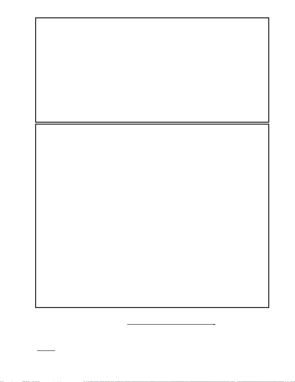
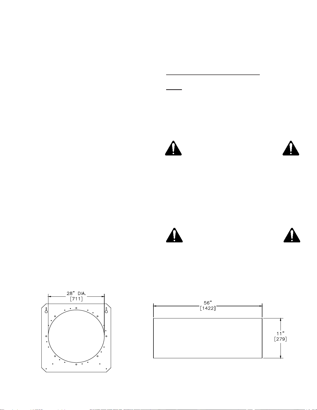
AREA= 56 X 11 = 616 SQ IN.
[3974 sq. cm.]
TRANSITION DISCHARGE OPENING
FAN DISCHARGE
AREA = 616 SQ. IN.
[3974 sq. cm.]
4. Fan and add-on heater mounting plane is
the same as your grain bin.*
*On MFS corrugated grain bins with a rolled in
base angle, the fan and heater mounting needs
to be 1½" lower.
Place the fan and heater on a mounting pad
or hang them off the side of the grain bin with
cables. Hanging installations can prevent the
costs and maintenance issues associated
with poured concrete pads. NECO premium
axial fans and axial heaters 24" and greater
are equipped with cable attachment brackets
(located at the handles). Use at a minimum a
3/16" galvanized steel (or stainless steel) wire
rope with appropriate ttings. Make certain the
units are secured to prevent any wind-induced
sideways motion. Centrifugal fans and heaters
can also be hung by cables, but due to their
weight and size the installations usually require
angle brackets and heavier wire rope. Speak to
your dealer or local millwright before attempting
cable installations.
It's very important that the unit is securely
mounted. If you choose a poured concrete slab
to mount your fan and heater on, it is recom-
mended that the slab be approximately 6 inches
thick [152] and 12" [305] wider on each side of
the fan/heater.
TIP: In order to reduce the chances of frost
heave, the pad can be poured on top of several
metal or concrete pilings which extend lower
than average frost depth.
5. Make sure the bin transition discharge is of
an equal area to your fan outlet. (See Figure 3.)
1. Using the appropriate caulk (caulking rated
at 200°F) caulk the Fan/Heater anges. Con-
nect the fan to the heater using nuts, bolts etc.
Hand tighten these fasteners only.
Note: use the appropriate adapter plates to
connect Fans/Heaters and transitions. Do not
weld onto transitions! Welding will cause
distortions which could lead to vibrations
during operation.
2. Place fan and heater on mounting pad.
Make sure the units sit level.
Any bending of the units will twist
the housing and cause future
problems.
Note: Frost heave can cause Fan/Transition
distortion and even vibration.
3. Wrench tighten the fan mounting bolts/nuts,
followed by wrench tightening of the heater
mounting nuts/bolts.
Make sure heater/fan mountings
are secure. A loose fan mounting
will cause the fan to vibrate. Vi-
bration can cause excessive wear
on the fan motor bearings.
4. Wrench tighten all ange fasteners.

10
GROUNDING
Connect your fan/heater to a ground rod
that's no more than 8' [2.4 m] away. Connect
the ground rod to the fan control panel with a
minimum 6 AWG solid bare copper wire that's
copper-clad and measures 5/8”diameter x 8 ft.
long. Install the rod two feet from the fan/heater
and/or bin foundation, and in accordance with
local requirements. The ground rod-to-fan con-
nection provides additional safety in the event
of a short or lightning strike. It also provides the
necessary grounding for operation and long life
of control circuits in the fan and heater.
Contact an electrical parts supplier to purchase
ground rods and wires. ENCO recommends the
rod not be driven in to dry ground. Follow the
steps below to ensure proper rod installation.
1. Dig a ditch and ll it with 1-2 gallons [3.8-7.6
Liters] of water.
3. Push a rod through the water and into the
ground.
4. Jab the rod up & down allowing the water to
work its way down the hole thus promoting
a conductive bond with the surrounding soil.
Drive the rod completely down.
5. Connect one end of the ground wire to the
rod with an appropriate ground clamp.
6. Connect the other end to a ground lug con-
nector inside the fan control box. Ground
wires should have no splices or breaks.
Don't use insulated wire for grounding.
NECO recommends that previously installed
units be checked for proper grounding.
Figure 4.
Vapor Valve Liquid Valve
Tee
Tank
Oil and Contaminants
Liquid
To Vaporizer
FUEL SUPPLY
Gas suppliers will provide a tank, rst stage
regulator, and the connection to the dryer. He
should test the connections for leaks. Storage
tanks must be located at least 25 feet from all
structures, depending on local codes. Check
with your gas supplier for code specications.
Route the supply line in so line breakage from
moving machinery is least likely. Line sizing
charts have been included in this manual to
assist in selecting the proper size pipe for the
supply line. See charts on the next page.
Propane
The inside of the supply tank must be free of
all contaminants. Raise one end of the liquid
propane supply tank as shown in Figure 4.
DO NOT USE supply tanks for propane if
they've previously been used for anhydrous
ammonia. Anhydrous ammonia residue will
rapidly corrode the brass components. Fuel
contaminants can also cause sooting and lead
to ignition problems.
NOTE: WARRANTY IS VOID IF FUEL
SUPPLY CONTAINS ANYHYDROUS
AMMONIA OR OTHER CONTAMINENTS.

11
PROPANE VAPORIZATION RATE - 1,000 [3785 Liters] GALLON TANK
Table 3 shows line lengths for systems running
on liquid propane between the liquid propane
tank and heater allowing pressure drop of 1 PSI
[6.9 kPa].
LINE SIZING CHART FOR LIQUID
PROPANE FUEL
Table 1. Propane Vaporization Rate (Approximations)
The supply tank should have a 1,000 gallon
[3785 Liter] capacity and be equipped with a
regulator capable of satisfying the BTU require-
ment of the heater at 35 PSI [241 kPa]. For
systems using liquid propane, the tank should
be equipped with a rst stage liquid regulator of
25 gallons [95 Liters] per hour at 50 to 60 PSI
[345-414 kPa] under ow. Consult your natural
gas representative for pressure available and
assistance with the installation.
The tank should be equipped with a vapor and
liquid tap. NECO recommends initial heater
start-up each day be done using the vapor tap.
The liquid tap should have a rapid ow shut-
off valve. If a line breaks the rapid ow shut-off
valve will stop the ow of propane. The rapid
ow valve should have a capacity of about 4
GPM [15 LPM]. To open this valve, open it part
way to allow the pressure to equalize between
the line and tank. Then fully open the excess
ow valve. Consult your propane supplier for
further information.
Table 1 shows the vaporization rate of a 1,000
gallon [3785 Liter] tank at various temperatures
when the tank is 25% full. If more heaters are
used simultaneously or if low ambient tem-
Table 2 shows line lengths for systems running
on gas vapor between the liquid propane tank
and the heater allowing pressure drop of 1 PSI
[6.9 kPa].
LINE SIZING CHART FOR
VAPOR PROPANE FUEL
IF OIL ENTERS THE HEATER
FUEL SYSTEM, THE WARRANTY
FOR FUEL TRAIN COMPONENTS
WILL BE VOID.
peratures are encountered, then a larger tank
should be installed or additional tanks added
in parallel. The vaporization rate of propane is
constantly changing due to variables of temper-
ature and amount of liquid in the tank.
Cold reduces propane vapor pressure consider-
ably. When it's very cold a propane-fueled heat-
er may not get enough fuel to reach the desired
operating temperature. Increase vapor pressure
by warming the tank with an approved electric
warming blanket.
CAUTION: SECURELY BLOCK
TANK WHEELS WHEN HEATER
CONNECTS TO A PORTABLE
PROPANE TANK
Outside Temperature Vapor Pressure Volume Fluid Volume BTUs/Hour
(000s)
Celsius Fahrenheit PSI kPa Feet3/Hour Meter3/Hour Gallons/Hour Liters/Hour
38 100 190 1310.0 710 20.1 19.5 73.8 1,794
32.2 90 165 1137.6 655 18.5 18 68.1 1,656
26.7 80 140 965.3 600 17.0 16.5 62.5 1,518
21.1 70 130 896.3 545 15.4 15.5 58.7 1,380
15.6 60 102 703.3 490 13.9 13.5 51.1 1,240
10 50 86 529.9 455 12.9 12.5 47.3 1,150
4.4 40 72 496.4 382 10.8 10.5 39.7 965
-1.1 30 58 399.9 327 9.3 9 34.1 826
-6.7 20 47 324.1 273 7.7 7.5 28.4 690
-12.2 10 3 255.1 218 6.2 6 22.7 551
-17.8 0 28 193.1 164 4.6 4.5 17.0 413
-23.3 -10 20 137.9 109 3.1 3 11.4 276

12
LINE SIZING CHART FOR LP - GAS VAPOR
LINE SIZING CHART FOR LP - GAS LIQUID
Table 2. Line Sizing Chart for Vapor Propane Fuel.
Table 3. Line Sizing Chart for Liquid Propane Fuel.
LP Vapor
Flow Rate
Line Length - in feet [meters]
Copper Tubing Schedule 40 Pipe
BTU per hour
(1,000s)
Feet3[meter3]
per minute 3/8" 1/2" 5/8" 3/8" 1/2" 3/4" 1" 1-1/4" 1-1/2" 2"
100 40 [1.1] 192' [58.5]
150 60 [1.7] 89' [27.1]
200 80 [2.3] 53' [16.2] 286' [87.2]
300 120 [3.4] 26' [7.9] 136' [41.5] 255' [77.7]
400 160 [4.5] 15' [4.6] 80' [24.4] 270' [82.3] 147' [44.8]
500 200 [5.7] 9' [2.7] 55' [16.8] 180' [54.9] 98' [44.8] 300' [91.4]
1,000 400 [11.8] 16' [4.9] 53' [16.2] 29' [8.8] 81' [24.7] 330' [100.6]
1,500 600 [17.0] 26' [7.9] 14' [4.3] 42' 12.8] 160' [48.8]
2,000 800 [22.7] 15' [4.6] 9' [2.7] 26' [7.9] 97' [29.6] 305' [93.0]
2,500 1000 [28.3] 10' [3.0] 17' [5.2] 65' [19.8] 200' [61.0]
3,000 1200 [34.0] 12' [3.7] 47' [14.3] 150' [45.7] 336' [102.4]
4,000 1600 [45.3] 28' [8.5] 87' [26.5] 319' [97.2]
5,000 2000 [56.6] 18' [5.5] 64' [19.5] 213' [64.9] 449' [136.8]
6,000 2400 [68.0] 13' [4.0] 43' [13.1] 155' [47.2] 328' [99.9] 1054' [321.3]
7,000 2800 [79.3] 10' [3.0] 33' [13.1] 115' [35.0] 245' [74.7] 809' ]246.6]
8,000 3200 [90.6] 26' [7.9] 93' [28.3] 190' [57.9] 628' [191.4]
LP Vapor
Flow Rate
Line Length - in feet [meters]
Copper Tubing - Type K Schedule 80 Pipe
BTU per hour
(1,000s)
Gallons / Hour
[liters / Hour] 3/8" 1/2" 5/8" 1/4" 3/8" 1/2" 3/4" 1" 1-1/4" - - -
915 10 [37.9] 328' [99.9] 1316' [401.1] 729' [222.2]
1,830 20 [75.7] 82' [25.0] 329' [100.3] 1410' [430] 182' [55.5] 825' [251.5]
3,660 40 [151.4] 20' [6.1] 82' [25.0] 354' [107.9] 46' [14.0] 205' [62.5] 745' [227.1]
5,490 60 [227.1] 9' [2.7] 36' [10.9] 157' [47.9] 20' [6.1] 92' [28.0] 331' [100.9]
7,320 80 [302.8] 20' [6.1] 83' [25.3] 11' [3.4] 51' [15.5] 187' [57.0] 735' [224.0]
9,150 100 [378.5] 13' [4.0] 56' [17.1] 7' [2.1] 33' [10.1] 119' [36.3] 470' [143.3]
12,810 140 [529.9] 29' [8.8.] 15' [4.6] 61' [18.6] 240' [73.2] 813' [247.8]
16,470 180 [681.3] 17' [5.2] 37' [11.3] 145' [44.2] 491' [149.7]
18,300 200 [757] 14' [4.3] 30' [9.1] 118' [36.0] 399' [121.6]
25,620 280 [1060] 15' [4.6] 60' [18.3] 204' [62.2]
27,450 300 [1136] 13' [4.0] 52' [15.8] 177' [53.9] 785' [239.3]

13
Natural Gas
When using natural gas, your gas company
will install a regulator that should be capa-
ble of producing 5 to 15 PSI [34 to 103 kPa]
under ow. [NOTE: NECO does not supply
regulators.] The regulator should be located at
or near the dryer to reduce the size of the sup-
ply line. Consult your natural gas representative
for pressure available and assistance in the
installation
The supply tank should be 1,000 gallon [3785
Liter] capacity and equipped with a regulator
capable of satisfying the BTU requirement of
the dryer at 35 PSI [241 kPa]. For systems us-
ing liquid propane, the tank should be equipped
with a rst stage liquid regulator of 25 gallons
[95 Liters] per hour at 50 to 60 PSI [345-414
kPa] under ow. (Consult your natural gas
representative for pressure available and assis-
tance with the installation.)
The tank should be equipped with a vapor and
liquid tap. It is recommended that initial heater
start-up each day should be done using the
vapor tap. The liquid tap should have a rapid
ow shut-off valve. In the event of a line break,
the rapid ow shut-off valve wll stop the ow of
propane. The rapid ow valve should have a
capacity of approximatly 4 GPM [15 Liters per
minute]. To open this valve, open part way only,
allow the pressure to equalize between the line
and tank. After the pressure has equalized, the
excess ow valve should be turned to the full
open position. Consult with your propane sup-
plier for further information.
AVOID START-UP PROBLEMS BY DOING
THE FOLLOWING
1) NECO LP model heaters require propane
vapor for start-up.
2) The supply tank should be tted with both a
vapor & liquid tap. A short line should come
out of each tap and meet at a “T” which then
has a line going to the heater.
3) Before starting the heater, start the fan,
close the liquid tap, and open the vapor tap.
4) Start heater up and let it run for at least 5
minutes.
5) Slowly open the liquid tap while slowly clos-
ing the vapor tap. Proceed until the liquid tap
is completely open and the vapor tap is com-
pletely closed. Don't ood the heater. Adjust
the vaporizer until the output plumbing from
the vaporizer is warm to the touch.
6) If a vapor tap is unavailable, the unit can be
started (with more difculty) on the liquid tap.
7) Start fan. Very slowly crack open the liquid
tap allowing just enough propane to vapor-
ize naturally and build up a few pounds of
pressure. Start heater. This will be a bit of
trial and error due to ambient temperature
conditions. Be very careful to allow only a
small amount of liquid to vaporize. Do not
throw open the valve, since this will cause a
ooding effect in the fuel loop.
8) If the heater is ooded by liquid propane,
shut off the tank supply. Open access panel
to allow vapors to dissipate. The fuel loop
may have to be taken apart at the union to
allow the LP to evaporate. The heater will
not start when ooded by liquid propane! Be
extremely careful of vapors. Never smoke
or have any type of ignition source near-
by.
SPECIAL NOTE: A heater equipped with a
vaporizer coil must use liquid propane. Vapor
propane is only used for initial warm-up. Us-
ing vapor propane constantly will overheat the
vaporizer causing shut down.
USE EXTREME CARE WHEN
WARMING A TANK—
NEVER USE A FLAME
DIRECTLY ON THE TANK

14
COMPONENT IDENTIFICATION AND
FUNCTION
Fenwall ignition module (PN 081251)
The ignition module controls the sequence of
events leading to ignition. It also monitors the
ame during operation. After power is applied
to the burner via the toggle switch, the Fenwal
module purges for 15 seconds. Next, the igni-
tion module sends power to the vapor solenoid
(liquid solenoid on LP models) causing the
spark generator to spark for four seconds. If the
ame probe senses ame, the solenoid valve(s)
will remain open. If no ame is detected the
solenoid valve(s) will close and stop the ow of
gas. The burner will attempt to light three times
before locking out. If lockout occurs see the
troubleshooting section. To reset the ignition
module and restart the ignition sequence, turn
the toggle switch OFF and back ON.
Vapor solenoid valve - 3/4" (PN 040875)
On LP models (except Hi-Lo option models) this
valve controls gas ow between the regulator
and burner. It opens during the ignition.
On natural gas models this valve controls gas
ow between the customer supplied regulator
and burner. It opens during the ignition.
On Hi-Lo models (both LP and natural gas) this
valve is opened to provide additional fuel to the
burner when the burner control calls for addi-
tional heat (high re position).
Liquid solenoid - 3/8" (PN 040880)
All LP models have this valve which controls
the ow of liquid propane before it gets to the
vaporizer. It opens during ignition and remains
open during operation.
Pressure gage
(PN 040885) (PN 040160-Liquid lled)
All models with a range of 0 - 15 PSI [0-100
kPa] have a pressure gage.
Burner High Limit (PN F048410)
The burner high limit is wired in series with the
circuit. It serves as a safety interlock and shuts
down the burner if the burner housing gets too
hot. It's set to trip at 200° F [93°C].
Vapor High Limit (LP models only)
(PN 040673)
The vapor high limit is wired in series with the
circuit. It serves as a safety interlock and shuts
down the burner in case of high vapor tempera-
ture at the vaporizer coil. This high limit is set to
trip at 160° F [71°C].
Vaporizer Coil (LP models only) (PN 043176)
The vaporizer coil is a piece of rolled schedule
80 pipe that allows liquid propane to expand
into a vapor that will burn at the point of ignition.
Air Switch (if equipped, PN F148003)
The Air Switch can be used as a safety device
that proves if there’s airow from the fan.
Honeywell Spark Generator (PN 040365)
The Spark Generator is used to provide the ac-
tual ignition spark. It's controlled and powered
by the Fenwal board.
Modulating Valve (MV models only)
(¾" - PN 2403046) (1¼" - PN 040124)
A modulating valve is available as an option
on LP or natural gas heaters. It automatically
adjusts the gas ow to regulate the underbin
temperature, thereby maintaining a set temper-
ature. A exible tube going from the valve to the
underbin area is lled with a liquid that expands
or contracts with temperature, thus regulating
the amount of gas going to the burner. Ther-
mostats or humidistats are not required when
using a modulating valve heater. The two termi-
nals on the terminal strip in the heater control
box (normally used for the control device) must
be jumped for the heater to operate. Monitor
temperatures under the bin with a thermometer.
Ball Valve (HL models only) (PN 044228)
A ball valve used on the low re side of the fuel
loop establishes the low re burner setting.
Y-Strainer (LP models only)
(3/8" - PN 040747) (½" - PN 2406001)
The Y-strainer is installed at the inlet of the

15
SETTING THE DRYING
TEMPERATURE
Although it is conventional to think of tem-
perature as a gauge to determine the drying
process, drying is actually accomplished by
delivering BTUs to the crop being dried. BTUs
are delivered as a result of air ow (CFM)
combined with a heat source which in this case
is the gas burner. Plenum temperature indicates
how hot it is under the bin, but not the amount
of energy being delivered. Adequate air ow is
equally important in the drying process.
An ideal ratio of air-to-gas is required for proper
combustion. CFMs delivered by the fan de-
creas as static pressure under the drying oor
increases (due to a deeper bed depth, foreign
material in the grain, or nature of the crop).
When CFMs decrease there is less air to mix
with the gas. Consequently the amount of fuel
going to the burner should be decreased. An
excess fuel-to-gas ratio will cause the ame to
get long and yellow, resulting in inefcient burn.
A good ame should be short, bushy, and blue.
If drying is to be done at static pressures in
excess of 3.5" [89] of water column, NECO rec-
ommends a centrifugal fan and heater be used.
control loop to trap contaminants coming from
the supply tank or supply line. Remove the pipe
plug periodically and clean out the Y-strainer.
Ball Valve (LP models only)
A ball valve is installed between the Y-strainer
and liquid solenoid as a means of manually
shutting off the supply of fuel to the burner.
Relief Valve (LP models only) (PN F048424)
Relief valves are installed to prevent excessive
pressure build up at points where gas can be
trapped in the fuel line.
Push Button Start/Stop Switch (PN F048401)
Regulator (LP models only)
(PN BY REGO, PN F048404)
(BY CASH-ACME PN 081961)
Regulators are used to provide a constant ow
of gas at a constant pressure. They are used
to adjust the ow of gas to establish a desired
operating temperature. As the adjusting screw
is turned is turned in, pressure will increase as
will gas ow. When the 3/4" vapor solenoid is
opened the operating pressure will be indicated
by the pressure gauge.
Igniter (PN 040155)
The igniter provides spark to the air gas mixture
via the spark generator which is controlled by
the fenwal module. Spark is present only during
the 4-second trial for ignition. The igniter gap
should be 3/16" [4.8].
Flame Probe (PN 040201)
When the ame probe senses ame, a signal
is sent to the fenwal ignition module indicating
it's ok for the solenoid valves to remain open.
A small amount of electricity is present in the
ame and a ame probe acts as a conductor so
that when ame is present the electrical cir-
cuit is completed. A minimum of 1 microamp is
required at the fenwal board to maintain ame.
The actual current may be checked by connect-
ing a microammeter to the FC test pins.
Fuse
(3.0 amp fuse - PN F048415)
(1.0 amp fuse - PN 081215)
A 3.0 amp slow-blow fuse is mounted on the
front of the control housing to protect electrical
components of the heater. A 1.0 amp fast-acting
fuse is included in the wiring harness circuitry
to protect the ignition board. When replacing
fuses make sure the correct amp-rated fuse is
installed.
Toggle Switch
(Switch - PN 043957)
(Switch boot - PN 083549)
Mounted on the front of the control housing, this
switch is used to provide power to the burner
and begin the ignition sequence. It is also used
to reset the fenwal module should the burner
fail to light after three attempts.
Power ON Lamp (PN 081984)

16
INITIAL START-UP USING PROPANE
When propane is the fuel source, the tank
should be equipped with a vapor and a liquid
tap. The liquid tap should have a rapid ow
shut-off valve. In the event of a line break, the
rapid ow shut off valve will stop the ow of
propane. It is recommended that initial heater
start-up each day should be done using the
vapor tap. When the heater has run on vapor
for 5 - 10 min., the liquid tap should be opened
slowly to avoid tripping the rapid ow shut-off
valve. When opening this valve, give it a partial
turn to allow the pressure to equalize between
the heater and tank before fully opening the
valve. After opening the liquid valve, close the
vapor valve. Starting on vapor ensures the
vaporizer coils are warmed before introducing
liquid propane and ensures that only vaporized
propane reaches the burner orice.
HEATER OPERATIONS
FOR MODELS:
04HC24NGV 04HC28NGV
04HC24LPV 04HC28LPV
Prior to starting the heater, make sure all of the
start-up procedures have been followed, and
that temperature control devices have been
wired into the heater.
1. Adjust the plenum thermostat to the desired
temperature. The thermostat must be wired
into the circuit before the heater will operate.
2. Turn on electrical power to the drying unit.
3. See page 16 "To avoid start-up problems".
4. Push the fan start button.
5. Turn the burner switch to the "ON" position.
The fan will now run for approximately for 15
sec. (to purge the drying system) before an
ignition will be made by the heater.
6. The heater will attempt to ignite the burner
for 4 seconds.*
The regulator setting determines the amount of
heat generated by the burner. (NECO supplies
a regulator only with LP heaters; the customer
or gas supplier provides a regulator for natu-
ral gas heaters). Temperature under the bin is
determined by the burner control whether it is a
thermostat, humidistat, or a modulating valve.
The burners can be operated without a burner
control mounted in the drying plenum but is
NOT recommended. Excessive temperatures
can arise under the drying oor leading to un-
even drying, scorched product or re. Addition-
ally, NECO highly recommends that a thermom-
eter be mounted near the burner control probe
under the bin as a safeguard that the burner
controls are operating at the desired setting.
When operating standard heaters which con-
trol the plenum temperature by cycling on and
off, try to set the temperature so that heater
does not continuously cycle. Attempt to adjust
the cycle time between 1½ to 3 minutes. Cycle
times will vary with each installation depending
on bin size, grain depth, fan size, crop, etc.
With the proper air to fuel ratio, a temperature
rise of approximately 100°F [38°C] can be ex-
pected. Heaters can be operated at a maximum
of 20 PSI [138 kPa], but typically operate be-
tween 5 and 15 PSI [34 and 103 kPa].
PRE-START CHECK
1. Be sure all electrical and fuel supplies are
turned off.
2. Check fan. Make sure fan is free of debris
and the fan blades turn freely. Fan guard
must be in place.
3. Check heater. Make sure heater is free of
debris and all covers are securely in place.
Heater must be electrically interlocked with
fan.
4. Check bin transition. Make sure transition is
free of debris and holes.
5. Make sure the thermostat and or other con-
trols are in place and in working order.
6. Occasionally a high limit switch will trip due
to vibration or during shipment. Push red
reset button if required.

17
HEATER OPERATIONS
FOR HI-LO MODELS:
04HL24NGV 04HL28NGV
04HL24LPV 04HL28LPV
Prior to starting the heater, make sure all of the
start-up procedures have been followed, and
that temperature control devices have been
wired into the heater.
NOTE: Hi-Lo Heaters are continuous-burn de-
vices. NECO highly recommends that you
install at least two or three thermometers
equally spaced along the circumference of
the grain bin plenum. Monitor the drying
heat to avoid excessive temperatues.
1. Adjust the plenum thermostat to the desired
temperature. The thermostat must be wired
into the circuit before the heater will operate.
2. Turn on electrical power to the drying unit.
3. See page 16 "To avoid start-up problems".
4. Push the fan start button.
5. Turn the burner switch to the "ON" position.
7. Once ignition has been obtained, allow the
burner to run for approximately 3 min. Adjust
the gas pressure so that the burner is on
75% of the time. Do not exceed 20 lbs. [138
kPa] of gas pressure.
8. Observe plenum temperature through a few
cycles to be sure the burner is operating
properly.
* If the burner fails to ignite after 4 seconds,
the unit will wait another 15 seconds before
trying a second attempt at ignition. If the
burner fails to ignite after three attempts,
you must reset the burner by ipping the
burner ignition switch off and then back
on. The heater will now make three more
attempts to ignite. If ignition fails after the
second series of attempts, see the trouble
shooting section in this manual.
6. After a 15 second purge cycle the heater will
ignite.*
7. Initially set the pressure regulator at a mid
range position of between 5 and 10 psi. [34
and 69 kPa] The higher the drying tempera-
ture and/ or the colder the ambient condi-
tions, the higher the pressure setting that
will be required.
8. After the burner has ignited, do the follow-
ing which will cause the burner to be on high
re.
A. Turn the cycling thermostat to its highest
setting.
B. Open the ball valve all the way. The ball
valve is opened fully when the handle is
parallel to the pipe train and is closed when
it is perpendicular to the pipe train.
9. Adjust the ball valve so that the burner is in
high ame approximately 50% of the time
and in low ame 50% of the time.
10. If the burner stays on high re continuously
or does not cycle to low ame frequently
enough then there is not enough gas avail-
able to satisfy the thermostat setting. To
correct this gradually increase the gas
pressure. If the burner stays on low ame
or does not cycle to high ame frequently
enough then the gas pressure is too high
and should be gradually reduced.
11. After adjustments are made to the regulator,
the ball valve may need to be repositioned
so that a frequency of 50% high to low re is
achieved.
* If the burner fails to light after four seconds,
the unit will wait another thirty seconds
before trying a second attempt at ignition.
If the burner fails to ignite after three at-
tempts, you must reset the burner by ipping
the burner ignition switch off and then back
on. The heater will now make three more
attempts to ignite. If ignition fails after the
second series of attempts, see the trouble
shooting section in this manual.

18
HEATER OPERATIONS FOR
MODULAR VALVE MODELS:
04MV24LPV 04MV28LPV
04MV28VPV 04MV24VPV
Prior to starting the heater, be sure to follow all
start-up procedures and to wire the temperature
control devices into the heater.
NOTE: Mod Valve Heaters are continuous-burn
devices. NECO highly recommends that you in-
stall at least two or three thermometers equally
spaced along the circumference of the grain bin
plenum. Monitor the drying heat to avoid exces-
sive temperatues.
1. Adjust the plenum thermostat to the desired
temperature. The thermostat must be wired
into the circuit before the heater will oper-
ate.
2. Turn the modulating valve to the minimum
setting.
3. Turn the electrical power to the heater ON.
4. See page 16 "To avoid start-up problems".
5. Push the fan start button.
6. Turn the burner switch to the ON position.
7. After a 15 second purge cycle the heater
will ignite.*
8. Once ignition has been obtained, allow the
burner to run for about thre (3) minutes. Set
the gas pressure (at the regulator) to 5 PSI
[34 kPa].
9. Adjust the modulating valve until bin tem-
perature stabilizes.
The Modulating Valve maintains a constant ple-
num temperatuer by allowing more gas to ow
to the burner if the plenum temperatue is lower
than desired or by restricting the gas ow if the
temperature is higher than desired.To set the
Modulating Valve, perform the following steps.
a. Determine the desired plenum temperature.
b. Using the vapor valve, set the operating
pressure at eight (8) psig for propane, or
three (3) psig for natural gas.
c. Adjust the valve's "T" handle until the bin
thermometer maintains the desired plenum
temperature. Turn the handle clockwise to
get a higher temperature or counterclock-
wise to get a lower temperature.
d. Set the regulator two (2) psig nighter than
the Modulating Valve operating condition
by turning the Modulating Valve handle two
revolutions, adjusting the regulator to the
desired pressuer, and then resetting the
Modulating Valve to the desired plenum
temperature.
10. A plenum thermometer is required to deter-
mine the temperature under the bin.
11. If the plenum does not come up to temper-
ature, gradually increase the gas pressure
at the regulator.
* If the burner fails to ignite after 4 seconds, the
unit will wait another 15 seconds before trying
a second attempt at ignition. If the burner fails
to ignite after three attempts, you must reset
the burner by ipping the burner ignition switch
off and then back on. The heater will now make
three more attempts to ignite. If ignition fails
after the second series of attempts, see the
trouble shooting section in this manual.
Coil adjustments may be needed for all models
using liquid propane vaporizers (LPV).

19
RECOMMENDED DRYING TEMPERATURES
RECOMMENDED DRYING TEMPERATURES OF NON-SEED CROPS (Note A)
CROP
IN-BIN
CONTINUOUS
STIR
DRYING
IN-BIN
BATCH
Corn 160° F [71° C] 140° F [60° C] 120° F [49° C]
Grain Sorghum 160° F [71° C] 140° F [60° C] 120° F [49° C]
Wheat 140° F [60° C] 120° F [49° C] 110° F [43° C]
Rice 105° F [40° C] 100° F [38° C] 90° F [32° C]
Oats 140° F [60° C] 120° F [49° C] 110° F [43° C]
Sunowers 110° F [43° C] 110° F [43° C] 100° F [38° C]
Soybeans 120° F [49° C] 120° F [49° C] 110° F [43° C]
Pinto Beans 100° F [38° C] 100° F [38° C] 100° F [38° C]
Table 4. Drying Temperature Recommendations
Temperature recommendations are based on commercial non-seed crops.
Determine the following:
•the type of crop you'll be drying,
•the target drying temperature
•the type of drying system to be used
Then refer to the table below for recommended
maximum plenum temperatures.
As long as moisture is evaporating from the
grain, the kernals remain relatively cool; but as
the kernals become dry they warm to the drying
temperature. Therefore, higher temperatures
increase not only the drying rate but also the
likelihood of damage to the grain. For optimal
results, you must monitor the temperatures
in the dryer at all times.
The drying front moves upward from the base
of the bin. Therefore, signicant overdrying
can occur at the base of the bin in the area
where the grain isn't being stirred.
Do not automatically set the plenum tempera-
ture to the maximum recommended tempera-
ture. Grain quality is enhanced when drying is
accomplished at lower temperatures.
Reduce the drying temperature as grain
reaches the target moisture content. Doing
so will prevent cracked grain and reduce re
hazard.
Be very careful when drying sunowers as they
highly ammable—especially the chaff. Do not
exceed temperature recommendatiions. Do not
let the area around the dryer become cluttered
with sunower residue or chaff.

20
WIRING DIAGRAMS
For wiring diagrams,
see the inside of the
control box's access panel.
This manual suits for next models
3
Table of contents
Other AGI Heater manuals
Popular Heater manuals by other brands

Rowi
Rowi HGK 1500/2/1 Basic operating instructions

Ducasa
Ducasa M-28 SPLIT user manual

Dimplex
Dimplex DHCB20 instruction manual

Helo
Helo Helo-WT Laava Instructions for installation and use

Dyna-Glo
Dyna-Glo WORKHORSE FA43 Series User's manual and operating instructions

Stelpro
Stelpro SCRSP Series Installer's guide