Operator Instructions
Operator Instructions 9
3 Operator Instructions
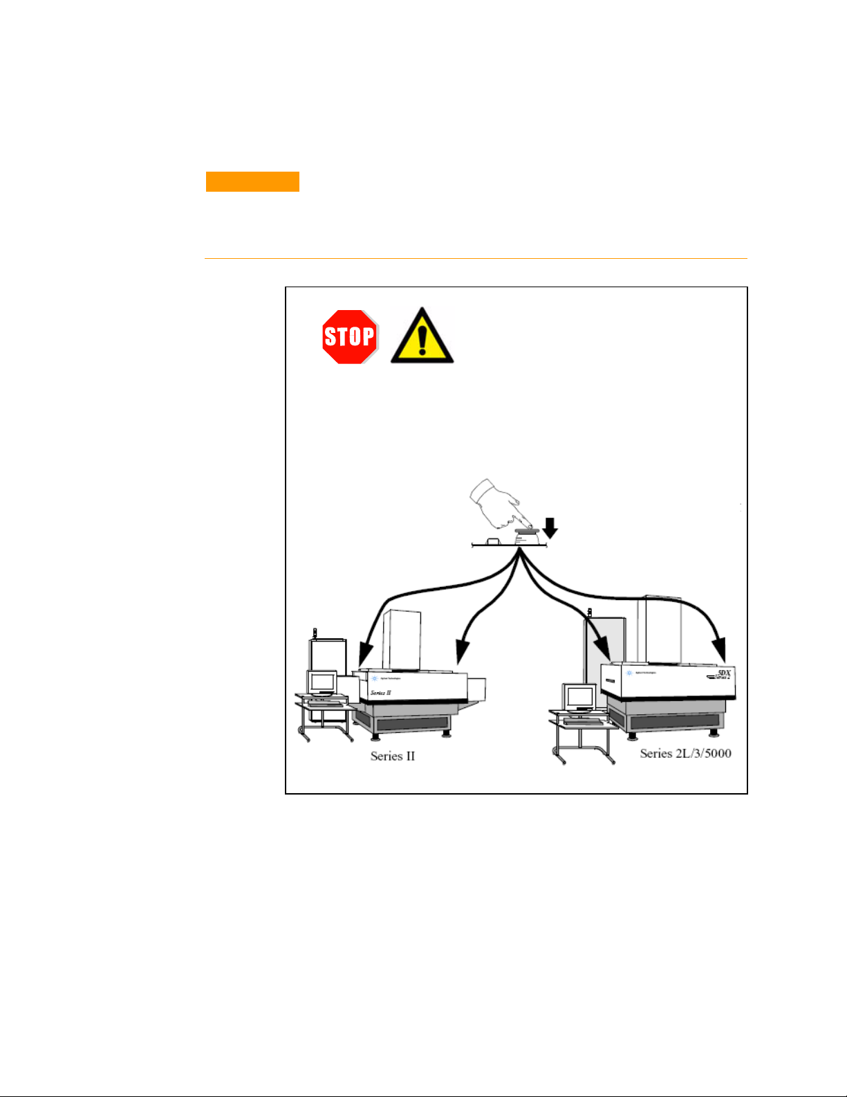
Startup the System
The Medalist 5DX is operated through the use of a user interface
running on the system controller. Before starting the system
software, verify that the X-ray has been enabled.
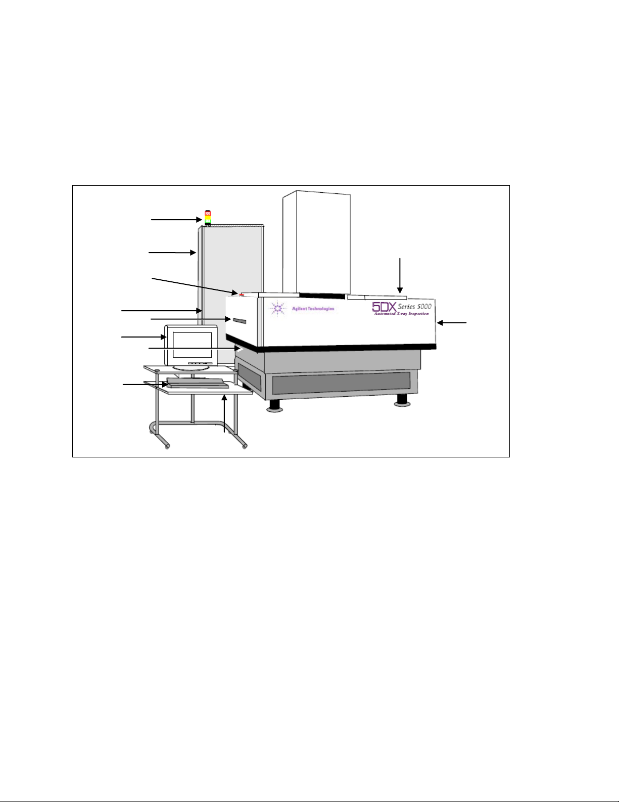
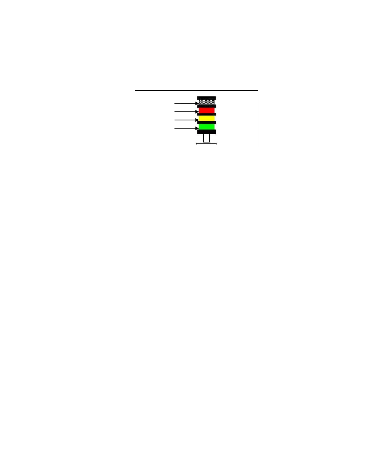
Verify the Safety Interlocks are Closed
On the operator control panel (see Figure 3) verify that the Safety
Interlocks green LED is lit. If it is not, call a service technician to
resolve the problem.
Verify the X-Ray Has Been Enabled
On the operator control panel (see Figure 3) verify that the X-ray
Control key is in the enabled position (1) and press the X-ray Control
enable button (1). Verify that the X-rays red LED is lit.
Log on to Microsoft Windows XP
Log on to Microsoft Windows using the Windows user name and
password provided by your administrator. When you log on, the
Medalist 5DX software starts automatically.
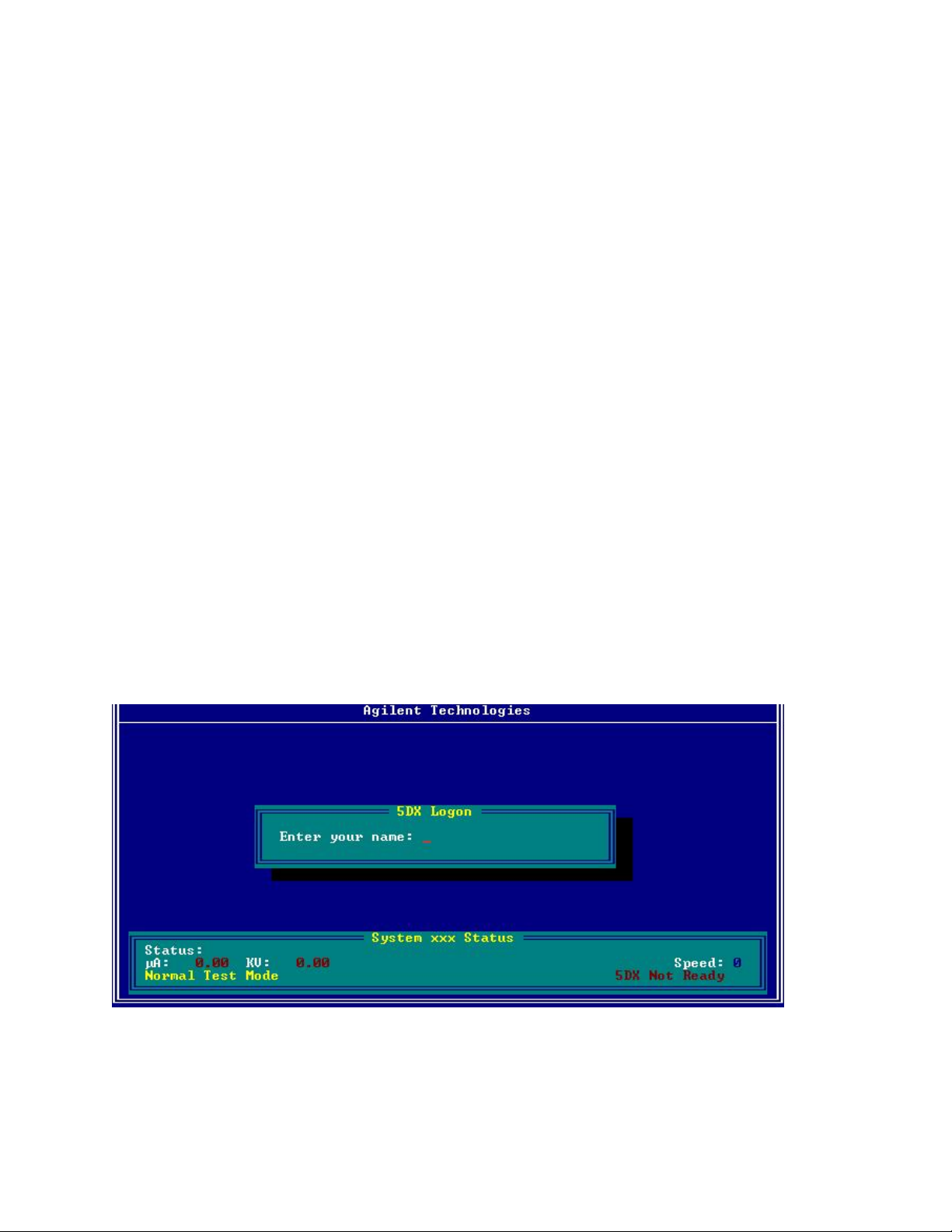
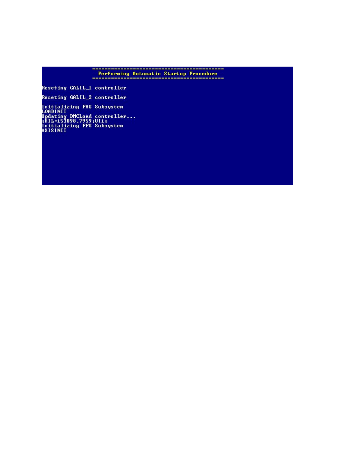
Log on to the Medalist 5DX User Interface
Log on to the Medalist 5DX user interface using the user name
provided by your administrator. Press the ‘Enter’ key to Login.
Figure 4 Login