Diagnostix™ Adstation™ d vic s.
Warning: Do not us batt ri s, l ctrical cords oth r than thos includ d with this
product or r plac m nt parts suppli d by th manufactur r.
Warning: This product may contain a ch mical known to th stat of California to
caus canc r, birth d f cts, or oth r r productiv harm.
Caution: Th standard mat rial us d is lat x-fr .
Attention: Som wall syst ms may includ up to 3 additional xt nsion modul s.
Tak car that th conn cting cabl do s not g t caught b hind th xt nsion
modul . Push th conn cting cabl into th groov provid d on th r v rs sid of
th xt nsion modul .
4. ATTACHMENT
a.) Wall Mounting
If mounting to th wall, us nclos d mounting t mplat .
b.) Attaching the Wall Mounting Plates
If mounting to wall studs, us wood scr ws only. If mounting b tw n studs, us th
nclos d molli s.
Tak th wall mounting plat and hold it onto th wall so that th scr ws can b
push d through th hol s of th mounting plat into th molli s.
Scr w in th scr ws with a scr wdriv r, as far as th y will go.
If th optional wallboard is purchas d, th mounting plat s com pr -attach d.
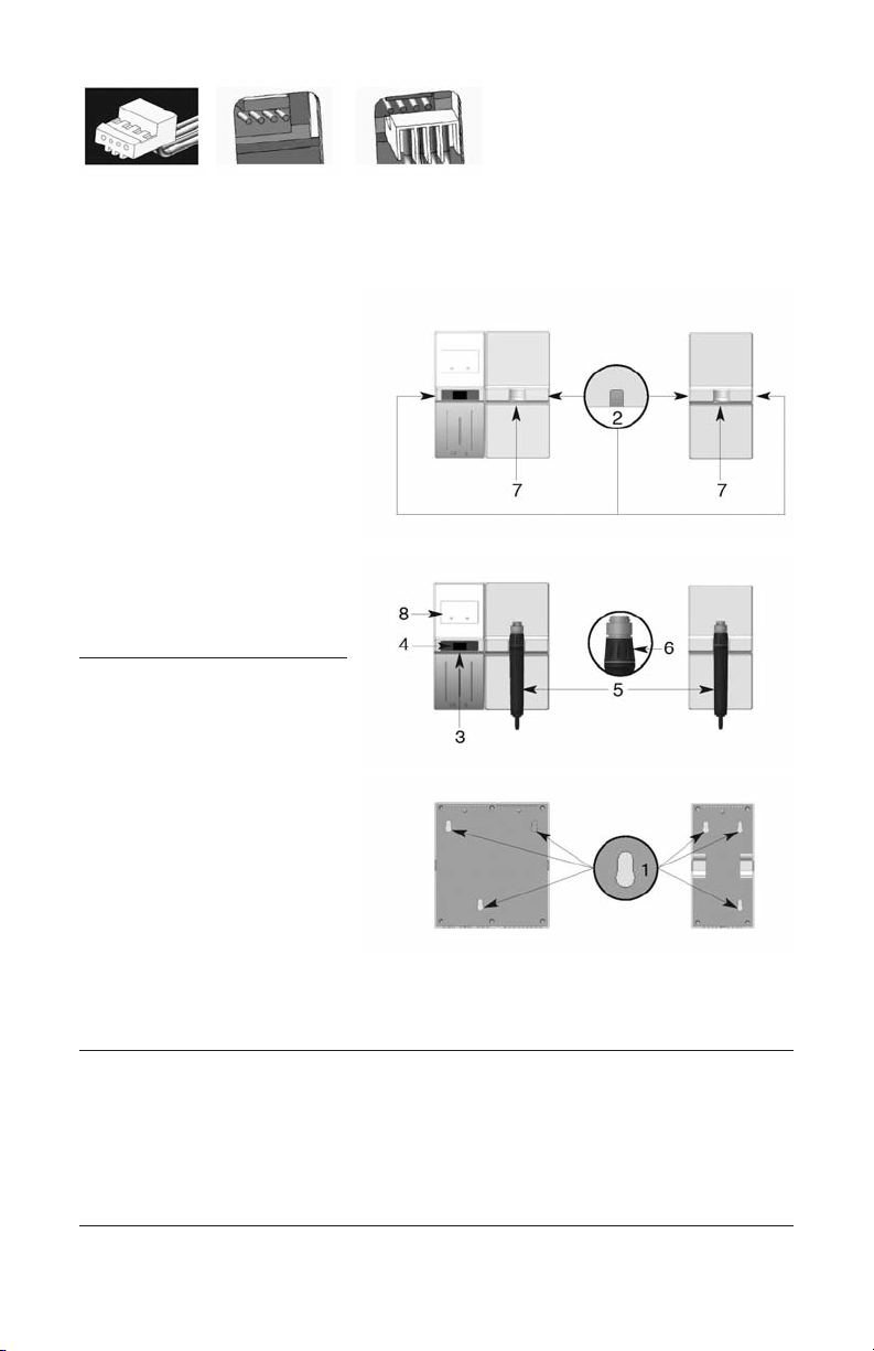
c.) Attachment of the ADC®Diagnostix™ Adstation™
Wh n all scr ws hav b n scr w d in tightly, tak th ADC®Diagnostix™
Adstation™ and guid th scr w h ads through th op nings (1). Th n pr ss th
ADC®Diagnostix™ Adstation™ downwards until it snaps into plac . (S illustration
on pag 7).
d.) Attachment of the Extension Module (If Included)
In ord r to add additional xt nsion modul s, th y must b l ctrically join d with
th transform r station b for mounting it on th wall.
Using th nclos d modul conn ction cabl , plug on sid of th conn ctor into th
sock t on th transform r modul locat d on th right sid transform r pan l.
Plug th opposit nd into th xt nsion modul contact, locat d on th l ft sid
pan l.
CAUTION: Mak sur wh n plugging th conn cting cabl , that th 4 contacts of
th sock t strip ar postivily conn ct d to th 4 contacts of th pin strip.