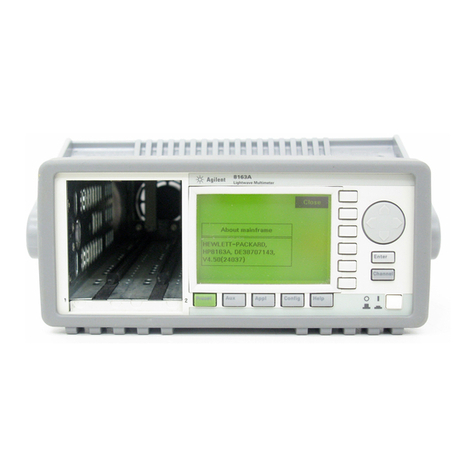
Agilent Technologies E5071C Installation and operating manual
Other Agilent Technologies Multimeter manuals
Agilent Technologies
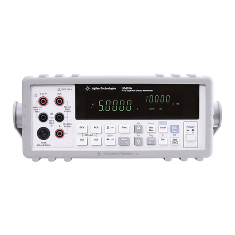
Agilent Technologies U3401A User manual
Agilent Technologies
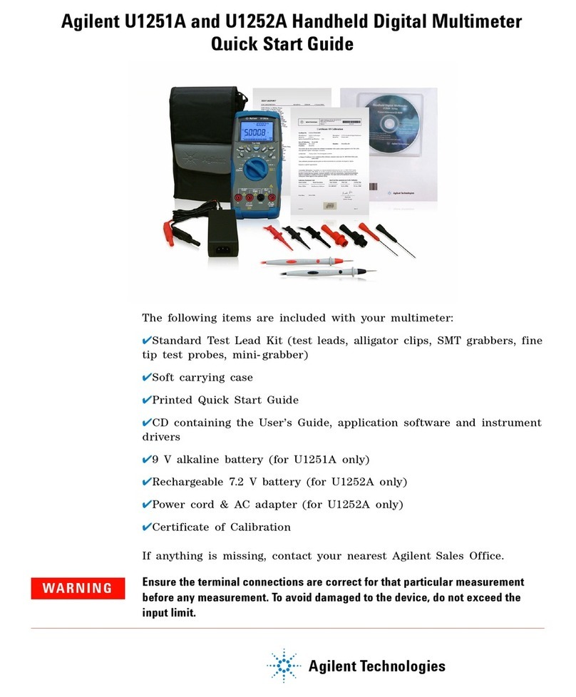
Agilent Technologies U1251A User manual
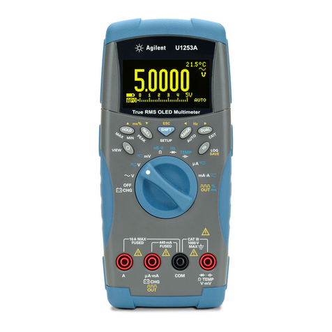
Agilent Technologies
Agilent Technologies U1253A Manual
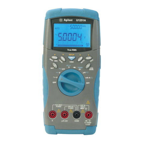
Agilent Technologies
Agilent Technologies U1251A User manual

Agilent Technologies
Agilent Technologies U2741A User manual
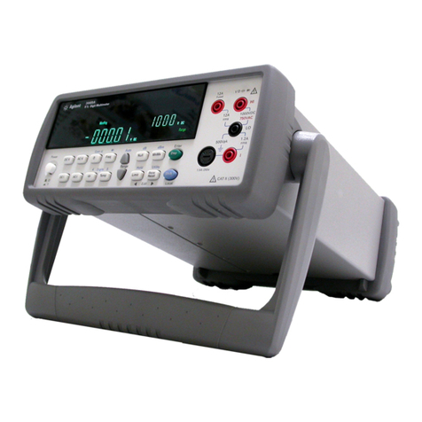
Agilent Technologies
Agilent Technologies 34405A Manual
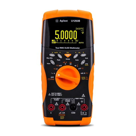
Agilent Technologies
Agilent Technologies U1253B User manual
Agilent Technologies
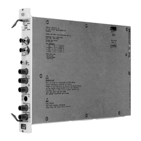
Agilent Technologies Agilent E1412A User manual
Agilent Technologies
Agilent Technologies U3402A User manual
Agilent Technologies
Agilent Technologies Agile or Elusive Signals Using Manual
Agilent Technologies
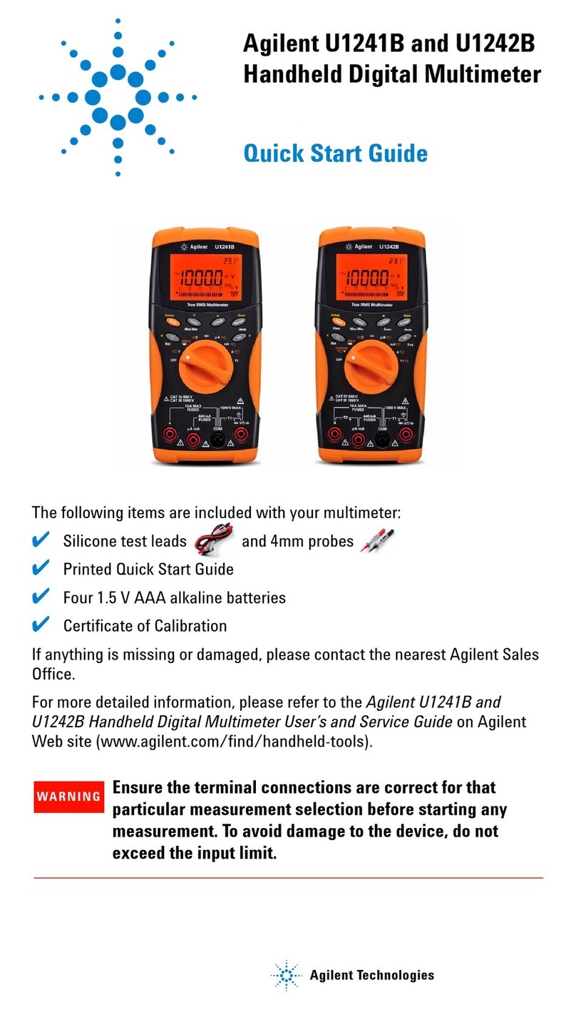
Agilent Technologies U1241B User manual

Agilent Technologies
Agilent Technologies U1253B Manual
Agilent Technologies
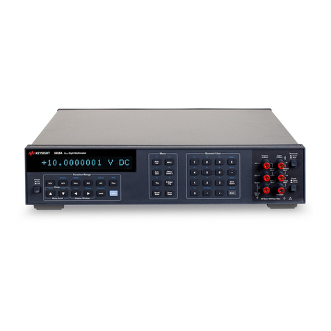
Agilent Technologies 3458A User manual
Agilent Technologies
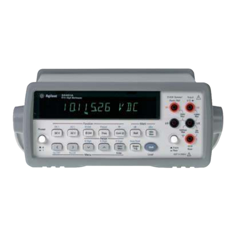
Agilent Technologies 34401A User manual

Agilent Technologies
Agilent Technologies U1273A User manual
Agilent Technologies
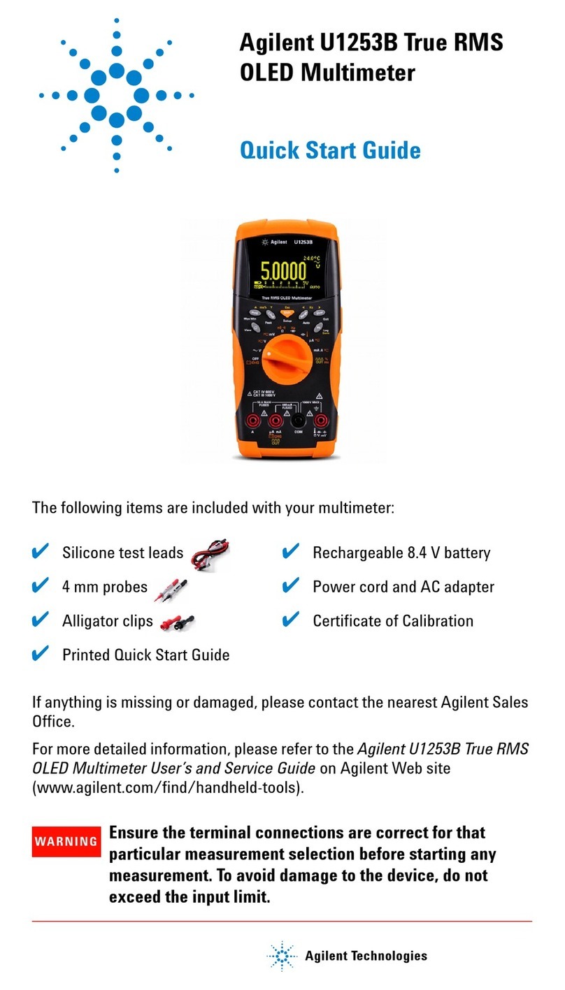
Agilent Technologies U1253B User manual
Agilent Technologies
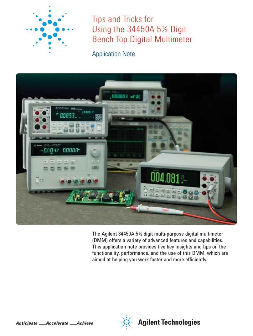
Agilent Technologies 34450A Installation and operating instructions
Agilent Technologies
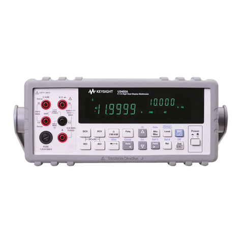
Agilent Technologies U3402A Manual
Agilent Technologies
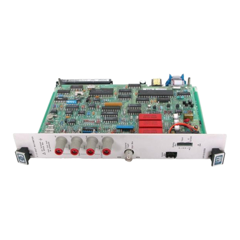
Agilent Technologies E1326B User manual
Agilent Technologies
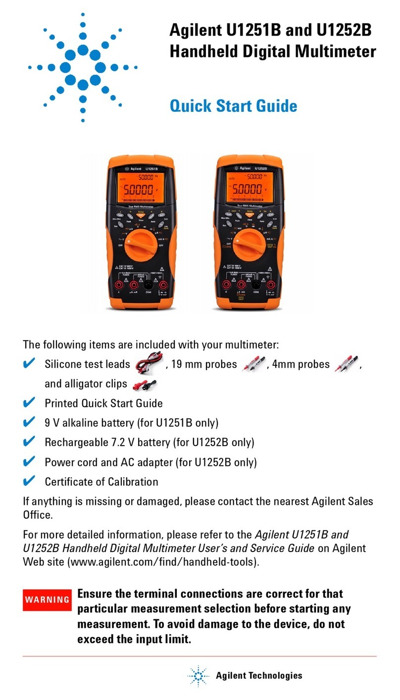
Agilent Technologies U1251B User manual
Popular Multimeter manuals by other brands

PeakTech
PeakTech 4000 Procedure of calibration

YOKOGAWA
YOKOGAWA 90050B user manual

Gossen MetraWatt
Gossen MetraWatt METRALINE DMM16 operating instructions

Fluke
Fluke 8846A Programmer's manual

Tempo Communications
Tempo Communications MM200 instruction manual

Elenco Electronics
Elenco Electronics CM-1555 operating instructions

