1 Introduction
The AWR300 is a high quality, ruggedized portable RFID reader for tags complying with the
ISO11784 / 11785 standard. It can read transponders with FDX-B and HDX technology. In
addition to the reading functions, the device can store up to 1.000.000 records in several groups
in the large internal memory. Each record also contains a timestamp plus a Visual ID and an Alert,
if available. The data are transmitted via the several available interfaces directly after reading like
USB, RS232, Bluetooth and Wi-Fi (optional).
The AWR300 also supports the Task-Mode and the DataBaseFunction (DBF) if the appropriate
definitions or data have been uploaded. This is usually done by 3rd-party Management Software.
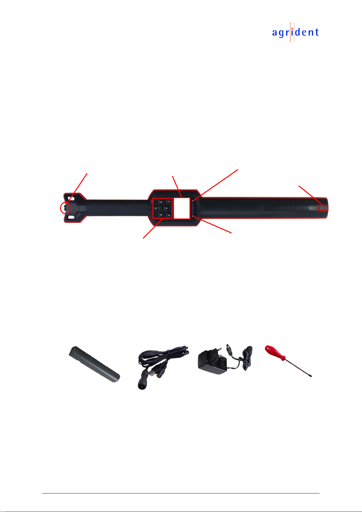
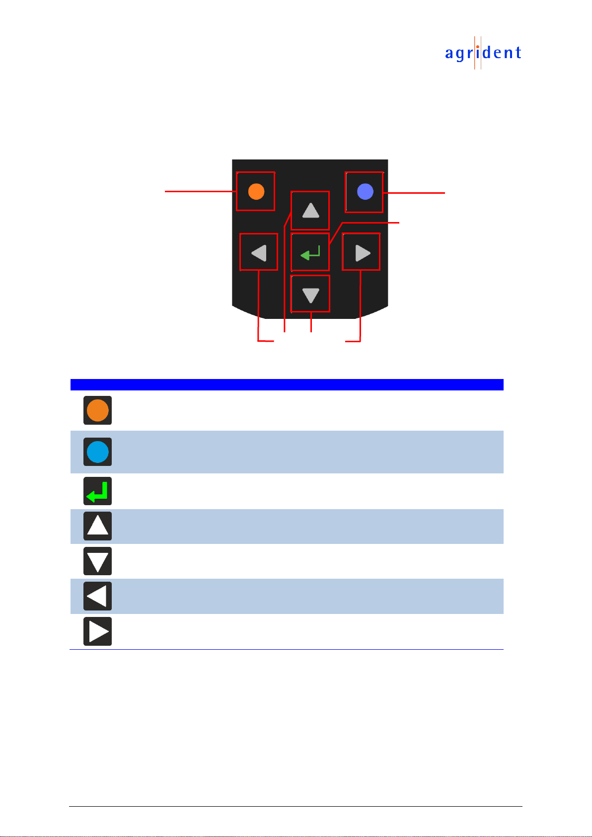
The reader has a large color display which can show many information at one glance. Together
with the seven keys it allows the easy and convenient navigation through menus and data. In
addition, the device has status LEDs above the display for charging and interface information and
multicolor LEDs at the tip which indicate the current reading state. The integrated speaker
provides acoustical feedback to the user and the vibrating handle is very useful in noisy
environments.
2 Before you start
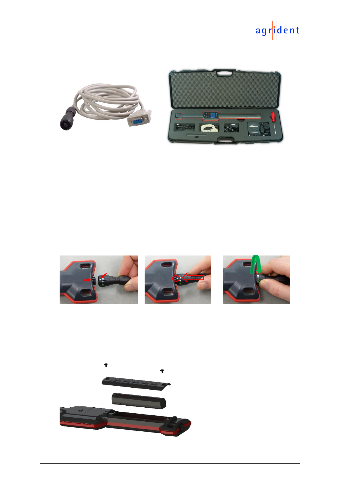
The internal high-capacity lithium-ion battery should be fully charged before the first use. The
battery can be charged by using the provided Y-Cable and power adapter. Please connect the Y-
Cable to the bayonet connector at the bottom of the reader and the power supply to the circular
connector of the Y-Cable.
The internal fast charging takes 3.5 hours maximum in case the battery was empty
completely. Please note that the battery will only be charged within a temperature
range of 0°C to 45°C (+32 to 113°F).