AgTerra SprayLogger E3 Datasheet

Installation &
Quick Start Guide
for
SprayLogger E3
Last Update: February 16, 2018

1
Disclaimer
The use of GPS devices, tablets and smartphones with MapItFast and associated AgTerra products
The internal GPS in your device can be used independently from online services to
automatically set location information in the app, which is recorded as latitude and
longitude.
GPS accuracy may be influenced by topology, environment and equipment.
Furthermore, the accuracy of the maps used in MapItFast (and its associated
products: Strider, SprayLogger and TrackItFast) are not guaranteed. Please use care
when using MapItFast.
MapItFast requires online data transfers for some features, such as accessing online
maps and sharing exported files. Accessing these features over data network services
may incur costs from your provider. If you use the app and data services on your
tablet, you are responsible for any fees that your service provider charges. Your
service provider is not the provider of MapItFast.
AgTerra Technologies makes no representations, expressed or implied, as to data
accuracy, completeness, validity or suitability. The end user assumes the entire risk as
to the quality of the data. AgTerra shall not be liable regardless of the cause or
duration, for any errors, inaccuracies, omissions, or other defects in, or untimeliness
or unauthenticity of data; or for any delay or interruption in the transmission of data
to the user; or for any losses, injuries or damages arising from its display or use.

2
Installation Components .............................. 3
E3 Package
Flow Sensors Installation.............................. 4
Plumbing
Wiring
Switches Installation..................................... 7
Unit Setup .................................................... 8
Connect to Device ........................................ 8
Pair with Bluetooth
MapItFast App.............................................. 8
Download lists
Connect unit
Update flow meter(s)
Start Spray Job ............................................. 11
Enter job information
Verify data recording
TABLE OF CONTENTS

3
Before installation, verify that all of the SprayLogger components have been included in
your shipment.
E3 Package
A. E3 SprayLogger Unit
B. VMZ Flow Sensor (one for each enabled flow port)
C. GPS Antenna
D. Power Cable
E. Switch Port Cable (one for each enabled switch port)
F. Flow Sensor Cable (Yellow 6-C)
Installation Components
The following items are generally included in a shipment,
however some components
may look different than those pictured and/or additional items may be included.
Refer to your packing slip for a detailed list of all items included in your shipment.
NOTE . . .

4
The VMZ induQ® flow sensor uses magnetic induction and works without any moving
parts. Because this type of flow sensor relies on electrical conductivity for operation,
it is important to install the meter in a manner that avoids electrical interference, air
bubbles in the flow stream (or running dry), and contamination from particles
settling out.
PLEASE READ THE OPERATING MANUAL INCLUDED WITH YOUR SENSOR.
This quick start guide only provides an overview.
To avoid false readings and contamination, mount the flow sensor in the lowest
possible position relative to the tank in a vertical position (flow going UP ↑).
If this is not possible, install in such a way that back washes or bubbles are
minimized. (See diagram).
BEST
RISK OF
CONTAMINATION
RISK OF
CONTAMINATION
RISK OF
RUNNING DRY
RISK OF BUBBLES,
RUNNING DRY
Flow Sensor Installation
Plumbing
–
VMZ Flow Sensor

5
WIRING
SprayLogger
E3B Unit
Pump
Tank
SprayLogger E3B
INSTALLATION DIAGRAM
Particulate
Filter
Bypass
Boom/
Section
GPS
6-C Cable for Flow
Sensor * (6-pin)
* Ports A, B & C for flow sensors. Ports 1-15
for switches (i.e., sections/booms).
PLUMBING
3-C Cable for
Switch * (3-pin)
Brown (not used)
(-) Black
(ground)
(+) Blue
(power)
Power
Flow
Sensor
Check valve is not required when SprayLogger
is used in combination with a switch. Check
valves help prevent false readings from air
bubbles or inadvertent fluid movement.
Check Valve (optional)
Install the backflow preventer/check valve before or after the flow meter. This
will help prevent false flow readings from bubbles and/or backwash.

6
An inlet section is not absolutely necessary, but to reach the highest accuracy use
straight inlet and outlet sections according to the Internal Diameter (ID). The inlet
section should be at least 10 x ID; the outlet section 5 x ID.
The inlet and outlet sections and the gaskets must have the same or a slightly
larger inside diameter than the measuring tube in order to achieve the specified
accuracy.
The sensor must be fully pressurized for operation.
The external GPS antenna must be installed for operation. Keep the cable away
from electrical fields to avoid interference*.
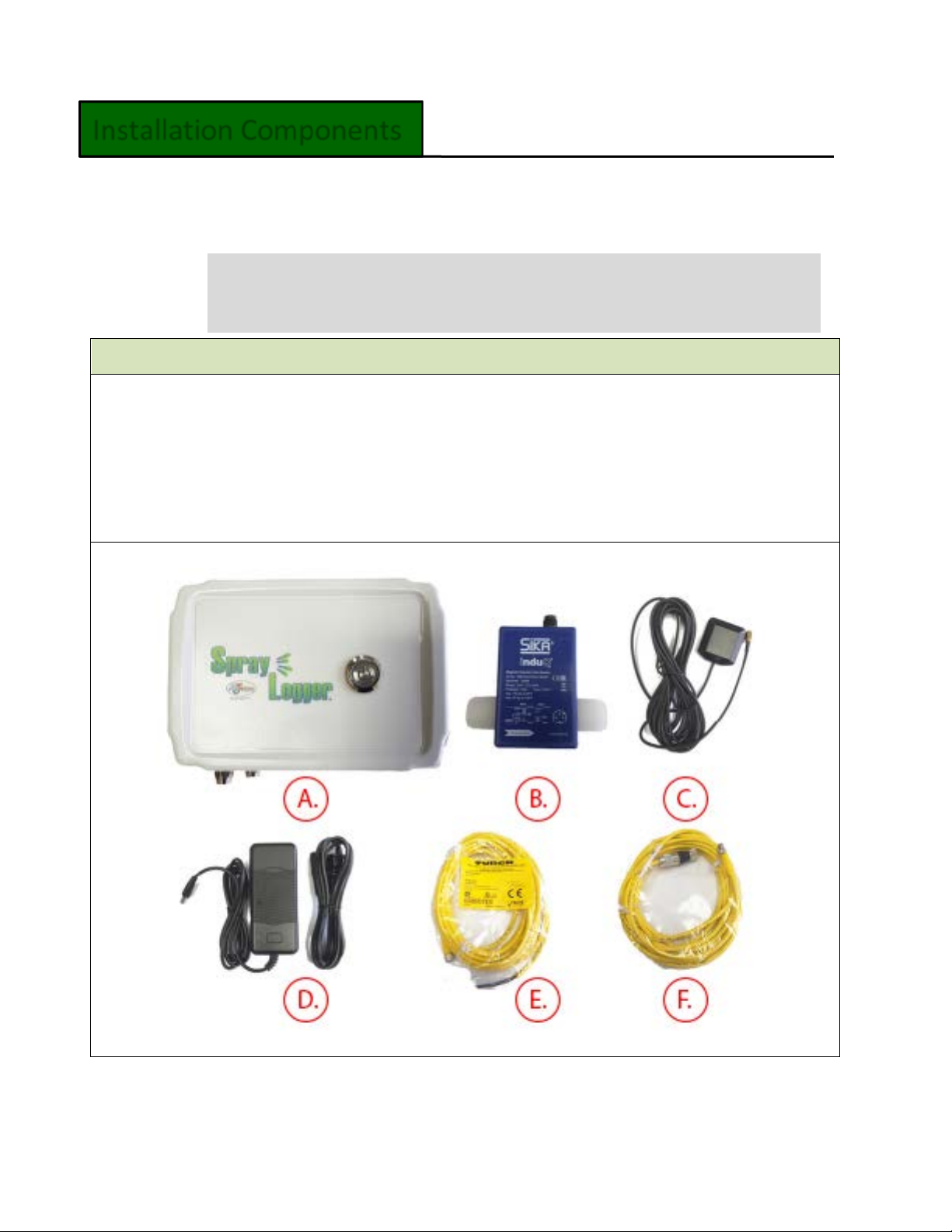
Once your sensor is installed, determine where your SprayLogger box will be
installed. Keep the following considerations in mind:
oVMZ sensors are sensitive to interference from nearby electrical fields. It is
imperative that the GPS antenna cable and flow sensor cables and
equipment wiring are installed away each other and from other electrical
wires and engine components on the vehicle; otherwise false readings will
result*.
oIf two VMZs are installed next to each other, make sure they are at least 2
inches apart. Otherwise, they may interfere with each other.
oYour SprayLogger is water resistant, but not water proof. It is best to place
the SprayLogger box in a dry location. While regular spray operations and
occasional rain showers are not harmful, submersion or heavy rain are.
oMake sure the external GPS antenna is attached to the SprayLogger box.
The antenna should be positioned at the center width of the vehicle with a
clear, open view of the sky.
Wiring
–
SprayLogger E3 to VMZ Flow Sensor
*To further reduce noise from electrical interferences, split ferrite cores can
easily be clipped on the flow sensor cable, power cable going into the
SprayLogger unit, and or other adjacent power lines.

7
oIf the SprayLogger unit is kept in a vehicle or container, check to verify that
the Bluetooth range is sufficient to stay connected to your device, and that
the GPS coordinates are accurate.
Connect your flow sensor to your SprayLogger E3 box using the 6-pin yellow
cable. The female end (green) connects to the flow sensor; the 6-pin male end
connects to a flow port on the SprayLogger. The cables may be clipped for
optimum length. If your cabling is too short, longer cables are available from
AgTerra.
1) If your SprayLogger E3 includes optional switch channels, use the 3-C yellow
cable(s) included in your shipment.
See the wiring diagram on the next page for additional information.
Switches Installation
Note, the cables for the flow sensors and switches look alike, as do their
ports on the SprayLogger box. Unless you have a custom configuration, flow
ports are labeled A, B and C on the box and the switch ports are labeled 1 –
15. Flow sensor cables (6-pin) will fit flow sensor ports, and only switch port
cables (3-pin) will fit switch ports. Contact AgTerra if you need additional
cables or extensions.

8

9
1) Plug SprayLogger E3 unit into the power supply. Please note that your power
supply may need to be powered with a vehicle power inverter (not included).
2) At least one flow sensor is required for SprayLogger. This sensor is always
connected to Port A on the box.
3) Use the power button to turn on the box (button will show blue light).
a. Important! Make sure that the blue LED light on your box blinks every
few seconds once you start a spray job in the MapItFast app. The
blinking light indicates that your box has a GPS signal. If the light does
not begin blinking within two minutes of powering on the box, try
rebooting the SprayLogger unit by powering it off and back on again.
You will first need to ‘pair’ your device with your SprayLogger.
1) Find Bluetooth settings on your mobile device.
2) Available devices will display in menu (may need to ‘Scan’ for
available devices). Be sure your unit is turned on.
3) When unit is located, your device will ask to confirm pairing of
SprayLogger box.
Connect to Device
Unit Setup

10
Once the unit is paired via Bluetooth, open the MapItFast app.
In the app:
1) Make sure SprayLogger menus are visible in lower and right-hand
sections of the screen.
a) If the menu is not visible, go to:
MapItFast Settings → SprayLogger → Show SprayLogger UI
b) Both SprayLogger windows can be expanded using arrow buttons
on bottom and side of MapItFast screen.
c) Tap on the settings button on the lower SprayLogger menu to
get the latest lists from the server. You must be connected to the
internet for this step.
MapItFast App

11
d) Select “Get SprayLogger Lists From Server.”
Note – this will upload lists (i.e. applicators, spray rigs, targets, tank mixes,
boom settings, etc.) that your administrator created in advance for your
company through the SprayLogger website at spraylogger.agterra.com. It
may take 2-3 attempts to get all your lists the first time. Repeat this step any
time the lists are updated by your administrator.
2) From the list of SprayLogger units, tap the unit you
would like to connect to.
Then tap the Connect button.
The button will change from “Connect” to “Disconnect”. You are now
connected to your SprayLogger unit via Bluetooth.
Note – if you temporarily lose or have intermittent connection with
the box, the menu may blink or turn yellow. If you completely lose
connection, it will turn red. Check to see that your device is not too
far away from the SprayLogger box, the units are not too shielded,
and the box is fully powered. Bluetooth has limitations!

12
3) Once connected to the SprayLogger unit, you will need to update the flow
meter settings. To do this, tap the settings button again.
4) Select Totals/Reprogramming in the menu.
5) In the next window, select Reprogram Unit from Cloud.
6) Your SprayLogger unit is now ready to start recording a spray job.

13
1) To begin a spray job, select the Start Job button.
2) Answer a few questions about the spray
job.
a. Required fields –Job Name (choose
from list or type new), Customer
(choose from list or type new), and
Spray Rig.
b. Optional fields - Tank Mix,
Applicators, Comments and
Application # are optional.
Note – While Tank Mix and
Applicators fields are not required for
starting a job in MapItFast, these data are necessary for
complete and accurate reporting.
Note - If names are not displayed, refer to item 1)c. in the
MapItFast app section.
3) You have now connected your SprayLogger unit and started a job. Observe the
pulse readings to confirm that the flow sensor detects flow when you spray.
Note - It is normal to see occasional random pulses even
when you are not actively spraying. These pulses,
however, should NOT be sufficient enough to record a
volume of spray. If they do, check for proper installation
– you may need a backflow preventer - and review
troubleshooting guides regarding electromagnetic
‘noise’ and how to minimize it.
All flow readings are automatically recorded on your device and will be
synchronized to your online SprayLogger account when an Internet connection
is established with your device.
Start Spray Job

14
4) If you have additional flow sensor or switch ports enabled on your E3, they will
appear on the Spray side menu highlighted in green:
Note – Tanks, switches, and their names must be set up in your online
account by your administrator before they become available on your device.
5) You may minimize the job details screen by tapping the menu arrows
. When the menu is minimized, it will display the total gallons
sprayed for your job, your vehicle speed, acres/miles (or hectares/kilometers)
sprayed and weather (temp, wind speed, humidity, wind direction).
Note- If you have an Internet connection, weather readings will be obtained
from the nearest weather station each hour. If the weather in your working
area differs or you do not have an Internet connection, you may tap
anywhere in the weather section and manually enter weather information.

15
For additional assistance, please refer to the online help guide after logging into
your account at https://spraylogger.agterra.com or contact your local dealer or
AgTerra office.
Thank you for using our products! We would love to hear from you. Contact us at
Table of contents
Popular Farm Equipment manuals by other brands

AGCO
AGCO Gleaner 3200 Series Workshop service manual

Headsight
Headsight Truesight Remote Quick reference guide

Alice's Garden
Alice's Garden CHABO CKC912BN manual

Checchi & Magli
Checchi & Magli WOLF PRO Use and maintenance manual

OREC
OREC RABBIT RM60W instruction manual

Titan Implement
Titan Implement 9300BU Series Operation and parts manual