Agu K-3 User manual

1
Owner Instructions
Italiano 2
English 8
Français 14
Deutsch 20
Español 26
Portuguese 32
38
44

2
1) VISIERA
Sede innesto superiore
Fermo visiera 1
Fermo visiera 2
Denti base movimento
Cursore fermo visiera
1.1) Meccanismo Visiera
Innesto superiore
Innesto inferiore 1
Denti visiera
Innesto inferiore 2
1.2) Rimozione/Installazione Visiera
La visiera è in policarbonato antigraffio ed è dotata di innesti che si inseriscono nelle
sedi della base movimento. I denti della visiera interagiscono con i denti della base
movimento per consentire la stabilità in apertura della visiera nelle diverse posizioni.
Vi consigliamo di eseguire le operazioni che seguono appoggiando il casco
su una superficie piatta.
Per rimuovere la visiera, ruotarla verso
l’alto fino alla totale apertura (1).
Partendo da uno dei due lati del casco,
tirare verso il basso il cursore del fermo
visiera (2) ed estrarre gli innesti di
aggancio della visiera. Ripetere
l’operazione anche dall’altro lato e
rimuovere la visiera.
Per installare la visiera, partendo da un
lato del casco, con la visiera
completamente sollevata, inserire
l’innesto superiore della visiera nella sua
sede della base movimento (3).
Successivamente, inserire gli innesti
inferiori 1 e 2 della visiera nei rispettivi
fermi visiera (eventualmente aiutandosi
tirando verso il basso il cursore) (4).
Ripetere l’operazione anche dall’altro
lato. Abbassare la visiera e verificarne il
buon funzionamento.
NB Nel caso in cui la visiera non
aderisca perfettamente al profilo del
bordo del casco, potrebbe essere
necessaria una regolazione o
sostituzione della base meccanismo
visiera. In questo caso rivolgersi ad
un punto di assistenza AGV.
THIS HELMET’S SHELL IS MADE OF THERMOPLASTIC
THIS HELMET’S LINER IS MADE OF POLYSTIRENE (EPS)
Italiano
1 2
3 4

3
2) SISTEMA DI VENTILAZIONE
Prese aria frontali
Presa aria muso
Canalizzazioni nel polistirolo
Presa aria top
Estrattori d’aria laterali
2.1) Apertura/chiusura prese aria superiori
Per aprire/chiudere le prese d’aria superiori, agire sul cursore fino a quando non si
sente lo scatto che indica il blocco del cursore in posizione.
2.2) Apertura/chiusura presa aria mentoniera
Per aprire/chiudere la presa aria mentoniera, abbassare/sollevare il meccanismo
della presa aria.
Meccanismo
Cursore
2.3) Rimozione/Installazione Paranaso
Il paranaso può essere rimosso estraendolo con delicatezza dalla sua sede. Per
rimontarlo, inserire le bandelle in plastica nelle apposite sedi e verificare che sia ben
fisso.
Chiuso
Aperto
Aperto
Chiuso

4
3) INTERNI
Cuffia
Guanciale destro
Guanciale sinistro
Paranuca
Protezioni anti-vento sotto gola
3.1) Rimozione/Installazione
guanciali
Per rimuovere i guanciali, impugnarli
nella parte anteriore vicino alla
mentoniera del casco e tirarli nella
direzione della freccia (1). Sfilare i
guanciali facendo passare il cinturino di
chiusura attraverso il foro ed estrarli (2).
Per rimuovere il rivestimento in tessuto,
procedere prima dalla parte posteriore
(3) e poi rimuovere l’anello di fissaggio
del passante sottogola ruotandolo (4).
1 2
3 4
La cuffia, i guanciali destro e sinistro e la protezione anti-vento sono estraibili e lavabili. Per rimuovere e installare gli interni, fare
riferimento alle istruzioni e figure che seguono. Per lavare gli interni, fare riferimento al libretto “Safety Warning”.

5
3.2) Rimozione/Installazione
Cuffia
Per rimuovere la cuffia, sganciare i 2
bottoni automatici posti nella zona
anteriore (1) ed i 2 nella zona posteriore
del casco (2) e sfilarla dal casco.
NB Estrarre la cuffia solo DOPO avere
sganciato tutti i bottoni automatici di
fissaggio per evitare di danneggiare i
bottoni stessi e di scucire le parti in
tessuto.
Per rimontare la cuffia, inserirla all’interno
del casco e fissarla agganciando i 2
bottoni posteriori (3) ed i 2 bottoni
anteriori (4)
1 2
3 4
1 2
3 4
3.3) Installazione/rimozione
protezione anti-vento sotto
gola
Per installare la protezione in tessuto,
inserire la bandella di plastica nello
spazio apposito sulla mentoniera. (1)
Per rimuovere la protezione, sfilarla
tirando nel senso della freccia. (2)
1 2
Per rimontare i guanciali, dopo aver
inserito l’anello rettangolare di fissaggio
(1) rivestire il guanciale con la copertura
in tessuto (2), accertandosi di accoppiare
correttamente guanciale e rispettiva
copertura. Infilare i guanciali nel casco
introducendo il cinturino nell’apposito
foro di passaggio (3). Inserire il guanciale
prima nella parte posteriore e poi in
quella anteriore (4). Verificare che i
guanciali siano perfettamente assicurati
al casco.

6
4) SISTEMA DI RITENZIONE
Ci sono tre tipi di sistemi di ritenzione:
- DD
- Fibbia a sgancio rapido
- Regolazione Micrometrica
Di seguito vengono riportate le indicazioni di utilizzo di tutte queste tipologie.
4.1) Sistema di ritenzione DD
Per allacciare il casco, passare il nastro
tra i due anelli (1), tirare la parte terminale
del nastro (2) fino a sentire il cinturino
premere contro la mascella ed
agganciare il bottone automatico anti-
sventolio (3), come indicato in figura.
Verificare che il casco rimanga ben saldo
in testa (vedere anche il paragrafo
“Scelta del casco appropriato” del libretto
“Safety Warning”).
Per slacciare il casco, sganciare il
bottone automatico tirando il terminale
del nastro ed allentare il nastro sfilandolo
dagli anelli, aiutandosi con la linguetta
rossa, come indicato in figura.

7
4.2) Sistema di ritenzione con
fibbia a sgancio rapido
Il sistema di ritenzione con fibbia a
sgancio rapido necessita di una
regolazione
al cinturino prima di essere allacciato.
Seguendo le indicazioni della figura che
segue, regolare la lunghezza del
cinturino aumentando o riducendo la
porzione di nastro che passa attraverso
l’anello (1) fino ad ottenere una calzata
del casco adeguata quando il cinturino è
allacciato.
Per allacciare il casco, inserire la fibbia
nel meccanismo di ritenzione (2) fino a
sentire lo scatto della chiusura (3).
Verificare che il casco rimanga ben saldo
in testa (vedere anche il paragrafo
“Scelta del casco appropriato” del libretto
“Safety Warning”).
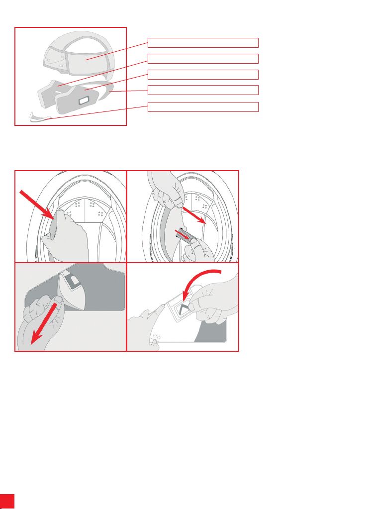
Per slacciare il casco, agire sul pulsante
rosso (1) per aprire il meccanismo di
ritenzione e poi sfilare la fibbia (2) come
indicato nella figura che segue.
4.3) Sistema di ritenzione con
regolazione micrometricaIl
sistema di ritenzione con regolazione
micrometrica necessita di una
regolazione al cinturino prima di essere
allacciato. Seguendo le indicazioni della
figura che segue, regolare la lunghezza
del cinturino aumentando o riducendo la
porzione di nastro che passa attraverso
l’anello metallico (1) fino ad ottenere una
calzata del casco adeguata quando il
cinturino è allacciato. Per allacciare il
casco, inserire la linguetta dentata nella
fibbia metallica (2) e spingerla a fondo
(3) fino a sentire il cinturino premere
contro la mascella. Il sistema con
regolazione micrometrica consente poi
un’ulteriore e più precisa “taratura” del
comfort e della vestibilità grazie alla
possibilità di usare il numero di scatti
della linguetta dentata che si preferisce
(e’ consigliabile comunque inserire la
linguetta nella fibbia il più a fondo
possibile).Verificare che il casco rimanga
ben saldo in testa (vedere anche il
paragrafo “Scelta del casco appropriato”
del libretto “Safety Warning”).
Per slacciare il casco, sollevare la levetta
rossa aiutandosi con la fettuccia di
tessuto (1) e poi sfilare la fibbia (2) come
indicato in figura.
N.B. PULSANTI/VELCRO POSTI SUL
SISTEMA DI RITENZIONE NON
HANNO FUNZIONE DI FISSAGGIO MA
SOLO DI ANTI-SVENTOLIO: NON
VANNO UTILIZZATI IN ALTERNATIVA
PER ALLACCIARE IL CINTURINO.

8
1) VISOR
Upper connection housing
Visor stop 1
Visor stop 2
Movement base teeth
Visor stop cursor
1.1) Visor Mechanism
Upper connection
Lower connection 1
Visor teeth
Lower connection 2
1.2) Visor Removal/Installation
The visor is made of non-scratch polycarbon and has connections that fit into the
housings on the movement base.The teeth of the visor interact with the teeth on the
movement base to offer stability while the visor is open in the various positions.
We recommend that you carry out the following operations while resting the
helmet on a flat surface.
To remove the visor, rotate it upwards
until it is completely open (1). Starting
from one of the two sides of the helmet,
pull the visor stop cursor down (2) and
extract the hook-up connections of the
visor. Repeat the operation on the other
side and remove the visor.
To install the visor, starting from one side
of the helmet, with the visor completely
raised, insert the upper connection of the
visor into its housing on the movement
base (3). Then insert lower connections
1 and 2 of the visor in the respective
visor stop devices (pulling the cursor
downwards if necessary) (4). Repeat the
operation on the other side. Lower the
visor and check that it works properly.
NB If the visor does not fit perfectly to
the profile of the edge of the helmet, it
might be necessary to adjust or
replace the visor mechanism base. In
this case, contact an AGV service
centre.
THIS HELMET’S SHELL IS MADE OF THERMOPLASTIC
THIS HELMET’S LINER IS MADE OF POLYSTIRENE (EPS)
English
1 2
3 4

9
2) VENTILATION SYSTEM
Front air inlets
Muzzle air inlet
Channels through polystyrene
Top air inlet
Side air extractors
2.1) Opening/closing upper air inlets
To open or close the upper air inlets, move the cursor until it clicks into position.
2.2) Opening/closing chin strap air inlets
To open or close the chin strap air inlets, raise or lower the air inlet mechanism.
Mechanism
Cursor
2.3) Nose guard Removal/Installation
The nose guard can be removed, gently extracting it from its housing.To refit it, insert
the plastic bands into their housings and check that it is secure.
Closed
Open
Open
Closed

10
3) INNERS
Cap
Right cheek pad
Left cheek pad
Neck guard
Throat wind shield
3.1) Cheek pad Removal/Installation
To remove the cheek pads, grip them at
the front near the helmet chin strap and
pull in the direction of the arrow (1).
Remove the cheek pads, passing the
closing strap through the holes and
extracting them (2).To remove the fabric
cover, proceed from the back (3) and
then remove the ring fastener of the
throat strap by twisting it (4).
1 2
3 4
The cap, right and left cheek pads and wind shield are removable and washable. To remove and install the inners, follow the
instructions and observe the figures below. To wash the inners, please see the “Safety Warning” booklet.

11
3.2) Cap Removal/Installation
To remove the cap, release the 2 press
studs at the front (1) and the 2 at the
back of the helmet (2) and slide them out
of the helmet.
NB Extract the cap only after releasing
all the press studs to avoid damaging
them and prevent damage to the
fabric parts.
To refit the cap, insert it inside the helmet
and clip the 2 press-studs at the back (3)
and the 2 at the front (4) into place.
1 2
3 4
1 2
3 4
3.3) Throat wind shield removal/
installation
To install the fabric shield, insert the
plastic band in the space in the chin
strap.
To remove the shield, slide it out, pulling
in the direction of the arrow.
1 2
To refit the cheek pads, after inserting
the rectangular ring fastening (1) cover
the cheek pad with its fabric cover (2)
ensuring that the cheek pad and its cover
are correctly coupled. Slide the cheek
pads into the helmet, slotting the strap
into the appropriate hole (3). Insert the
rear part of the cheek pad first followed
by the front part (4). Check that the
cheek pads are perfectly secured to the
helmet.

12
4) RETENTION SYSTEM
There are three types of retention system:
- DD
- Quick release buckle
- Micrometric adjustment buckle
The instructions for the use of all three types are given below.
4.1) DD retention system
To fasten the helmet, slot the tape
through the two rings (1), pull the end of
the tape (2) until the strap presses
against the jaw and click the anti-flapping
press-stud (3) into place as shown in the
figure. Check that the helmet fits snugly
(see the paragraph entitled “Choosing
the right helmet” in the “Safety Warning”
booklet).
To remove the helmet, release the press-
stud by pulling the end of the tape and
loosen the tape, pulling it through the
rings, using the red tab as shown in the
figure.

13
4.2) Quick release buckle retention
system
With the quick release buckle retention
system, the strap must be adjusted
before being fastened.
Following the indications of the figure
below, adjust the length of the strap,
lengthening or shortening the portion of
tape that passes through the metal ring
(1) until the helmet fits snugly when the
strap is fastened.
To fasten the helmet, slot the buckle into
the retention mechanism (2) until it clicks
closed (3).Check that the helmet fits
snugly (see the paragraph entitled
“Choosing the right helmet” in the “Safety
Warning” booklet).
To remove the helmet, use the red button
(1) to open the retention mechanism and
then open the buckle (2) as shown in the
figure below.
4.3) Micrometric adjustment buckle
retention
systemWith the micrometric adjustment
retention system, the strap must be
adjusted before being fastened.
Following the indications of the figure
below, adjust the length of the strap,
lengthening or shortening the portion of
tape that passes through the metal ring
(1) until the helmet fits snugly when the
strap is fastened.
To fasten the helmet, slot the serrated
tab into the metal buckle (2) and push it
as far as possible (3) until the strap
presses against the jaw.The micrometric
adjustment system enable further, more
precise “calibration” of comfort and fit
thanks to the possibility to use the
preferred number of positions on the
serrated tab (It is best to insert the tab as
far as possible into the buckle).
Check that the helmet fits snugly (see
the paragraph entitled “Choosing the
right helmet” in the “Safety Warning”
booklet).
To remove the helmet, lift the red lever
using the ribbon (1) and then open the
buckle (2) as shown in figure below.
N.B. BUTTONS/VELCRO POSITIONED
ON THE RETENTION SYSTEM ARE
NOT FASTENINGS BUT ARE ONLY TO
PREVENT FLAPPING: THEY MUST
NOT BE USED AS AN ALTERNATIVE
TO FASTENING THE STRAP.

14
1) ECRAN
Logement attache supérieure
Arrêt écran 1
Arrêt écran 2
Dents base mouvement
Glissière arrêt écran
1.1) Mécanisme écran
Attache supérieure
Attache inférieure 1
Dents écran
Attache inférieure 2
1.2) Démontage/Remontage écran
L’écran est en polycarbonate anti-éraflures et est muni d’attaches qui sont introduites
dans les logements de la base mouvement. Les dents de l’écran interagissent avec
les dents de la base mouvement pour permettre d’obtenir une stabilité dans
l’ouverture de l’écran, dans les différentes positions.
Nous vous conseillons d’exécuter les opérations qui suivent en posant le
casque sur une surface plate.
Pour démonter l’écran, le relever jusqu’à
son ouverture totale (1). En partant d’un
des deux côtés du casque, tirer vers le
bas le curseur de l’arrêt écran (2) et
extraire les attaches d’accrochage de
l’écran. Répéter l’opération également
de l’autre côté et enlever l’écran.
Pour monter l’écran, en partant d’un côté
du casque, avec l’écran complètement
relevé, introduire l’attache supérieure de
l’écran dans son logement de la base
mouvement (3). Successivement,
introduire les attaches inférieures 1 et 2
de l’écran dans les arrêts écran
respectivement (éventuellement
aiutandosi en tirant vers le bas le
curseur) (4). Répéter l’opération
également de l’autre côté. Abaisser
l’écran et en vérifier le fonctionnement
correct
NB Dans le cas où l’écran n’adhère
pas parfaitement au profil du bord du
casque, un réglage ou remplacement
de la base mécanisme écran pourrait
être nécessaire.Dans ce cas contacter
un point d’assistance AGV.
THIS HELMET’S SHELL IS MADE OF THERMOPLASTIC
THIS HELMET’S LINER IS MADE OF POLYSTIRENE (EPS)
Français
1 2
3 4

15
2) SYSTÈME DE VENTILATION
Prises d’air face
Prise d’air nez
Canalisations dans le polystyrène
Prise d’air top
Extracteurs d’air latéraux
2.1) Ouverture/fermeture aérateurs supérieurs
Pour ouvrir/fermer les aérateurs supérieurs, agir sur la glissière jusqu’à entendre un
déclic qui indique le bloc de la glissière en position.
2.2) Ouverture/fermeture aérateur mentonnière
Pour ouvrir/fermer l’aérateur de la mentonnière, abaisser/soulever le mécanisme de
l’aérateur
Mécanisme
2.3) Démontage/Montage Protège-nez
Le protège-nez peut être démonté en l’extrayant délicatement de son logement.Pour
le remonter, introduire les bandes en plastique dans les logements spécialement
prévus et vérifier qu’il soit bien fixé.
Ouvert
Fermé
Ouvert
Fermé
Curseur

16
3) PARTIES INTERNES
Coiffe
Coussin de joue droit
Coussin de joue gauche
Tour de cou
Protections anti-vent jugulaire
3.1) Démontage/Remontage des
coussins de joue
Pour enlever les coussins de joue, saisir
la partie avant à côté de la mentonnière
du casque et tirer dans la direction de la
flèche (1).Enlever les coussins de joue en
faisant passer la sangle de fermeture à
travers le trou et les enlever (2). Pour
enlever le revêtement en tissus, procéder
en premier par l’arrière (3) et puis enlever
l’anneau de fixation du passant de la
mentonnière en le faisant tourner (4).
1 2
3 4
La coiffes, les coussins de joue droite et gauche et la bavette anti-remous peuvent être démontés et lavés facilement. Pour démonter
et remonter la partie interne, lire les instructions et consulter les figures suivantes. Pour laver la partie interne, consulter la notice
“Safety Warning”.

17
3.2) Démontage/Remontage Coiffe
Pour enlever la coiffe, décrocher les 2
boutons-pressions placés dans la zone
avant (1) et les 2 dans la zone arrière du
casque (2) et le dégager du casque.
NB Extraire la coiffe uniquement
APRÈS avoir décroché tous les
boutons-pressions de fixation pour
éviter d’endommager les boutons et
de découdre les parties en tissus.
Pour remonter la coiffe, l’insérer à
l’intérieur du casque et le fixer en
accrochant les 2 boutons arrière (3) et
les 2 boutons avant (4)
1 2
3 4
1 2
3 4
3.3) Montage /démontage bavette
anti-remous jugulaire
Pour monter la bavette en tissus, insérer
sur la bande de plastique dans l’espace
prévu sur la mentonnière.
Pour démonter la protection, l’extraire en
tirant dans le sens de la flèche.
1 2
Pour remonter les coussins de joue,
après avoir introduit l’anneau
rectangulaire de fixation (1) revêtir les
coussins de joue avec la couverture en
tissus (2), en vérifiant de coupler
correctement coussin de joue et
couverture respective. Enfiler les
coussins de joue dans le casque en
introduisant le sangle dans le trou de
passage spécialement prévu (3).
Introduire les coussins de joue en
premier dans la partie arrière et puis
dans celle avant (4). Vérifier que les
coussins de joue sont parfaitement fixés
au casque.

18
4) SYSTEME D’ATTACHE
Il y a trois sortes de systèmes d’attache:
- 2D
-Boucle à retrait rapide
-Réglage Micrométrique
Ci-dessous, vous trouverez les indications pour les utiliser toutes.
4.1) Système d’attache 2D
Pour attacher le casque, passer la sangle
entre les deux anneaux (1), tirer le bout
de la sangle (2) jusqu’à ce que la
jugulaire appuie contre la mâchoire et
attacher le bouton automatique pour
l’empêcher de battre avec le vent (3),
comme indiqué sur la figure.
Vérifier que le casque reste bien en
place sur la tête (voir aussi le paragraphe
“Choix d’un casque approprie” du livret
“Safety Warning”).
Pour détacher le casque, décrocher le
bouton automatique en tirant sur le bout
de la jugulaire et agrandir la sangle en la
retirant des anneaux et en s’aidant de la
languette rouge, comme indiqué sur la
figure.

19
4.2) Système d’attache avec boucle
à retrait rapide
Le système d’attache avec boucle à
retrait rapide a besoin d’un réglage de la
jugulaire avant d’être attaché.
En suivant les indications de la figure
suivante, régler la longueur de la
jugulaire en augmentant ou en réduisant
la partie de sangle qui passe dans
l’anneau métallique (1) jusqu’à ce que
vous sentiez que le casque vous tient
bien la tête une fois la jugulaire
attachée.
Pour attacher le casque, insérer la
boucle du mécanisme d’attache (2)
jusqu’à ce que vous entendiez le déclic
de fermeture (3).
Vérifier que le casque reste bien en
place sur la tête (voir aussi le paragraphe
“Choix d’un casque approprie” du livret
“Safety Warning”).
Pour détacher le casque, utiliser le
bouton rouge (1) pour ouvrir le système
d’attache, puis retirer la boucle (2)
comme indiqué sur la figure suivante.
4.3) Système d’attache avec
réglage micrométrique
Le système d’attache avec réglage
micrométrique a besoin d’un réglage de
la jugulaire avant d’être attaché.
En suivant les indications de la figure
suivante, régler la longueur de la
jugulaire en augmentant ou en réduisant
la partie de sangle qui passe dans
l’anneau métallique (1) jusqu’à ce que
vous sentiez que le casque vous tient
bien la tête une fois la jugulaire attachée.
Pour attacher le casque, insérer la
languette crantée dans la boucle en
métal (2) et la pousser à fond (3) jusqu’à
ce que vous sentiez la jugulaire appuyer
contre la mâchoire. Le système avec
réglage micrométrique permet par la
suite un autre “réglage” plus précis du
confort et de l’aisance, grâce à la
possibilité d’utiliser le nombre préféré de
crans de la languette crantée (Nous vous
conseillons tout de même d’insérer la
languette la plus possible dans la
boucle).Vérifier que le casque reste bien
en place sur la tête (voir aussi le
paragraphe “Choix d’un casque
approprie” du livret “Safety Warning”)
Pour détacher le casque, soulever le
levier rouge en s’aidant du morceau de
tissu (1) puis décrocher la boucle (2),
comme indiqué sur la figure.
NB LES BOUTONS/VELCRO PLACES
SUR LE SYSTEME D’ATTACHE NE
SERVENT PAS A FIXER LA JUGULAIRE
MAIS SEULEMENT A L’EMPECHER DE
BATTRE AVEC LE VENT : ILS NE
DOIVENT PAS ETRE UTILISES COMME
SYSTEME D’ATTACHE POUR LA
JUGULAIRE.

20
1) VISIER
Oberer Eingriffsitz
Visierhalter 1
Visierhalter 2
Zähne für Grundbewegung
Schieber Visierblockierung
1.1) Visiermechanik
Obiger Eingriff
Unterer Eingriff 1
Visierzähne
Unterer Eingriff 2
1.2) Entfernung/Montage desVisiers
Das Visier ist aus kratzfestem Polycarbonat und ist mit Eingriffen ausgestattet, die sich
in die Sitze der Grundbewegung einhaken. Die Zähne des Visiers greifen in die Zähne
der Grundbewegung ein, um eine Stabilität bei der Visieröffnung in verschiedenen
Positionen zu gewährleisten.
Während diesem Vorgang empfehlen wir, den Helm auf eine flache Ebene zu
legen.
Um das Visier abzunehmen, muss es
vollständig geöffnet werden (1). An eine
der beiden Seiten des Helms den
Schieber der Visierblockierung nach
unten ziehen (2) und die
Verbindungseingriffe des Visiers
herausziehen. Diesen Vorgang auch auf
der anderen Helmseite wiederholen und
das Visier entfernen.
Für die Montage, bei vollständig
hochgehobenes Visier, an einer der
beiden Helmseiten den oberen Eingriff
des Visiers in den Sitz der
Grundbewegung einstecken (3). Danach
die unteren Eingriffe 1 und 2 des Visiers
indie entsprechendenVisierblockierungen
einrasten (eventuell kann man sich durch
Herunterziehen des Schiebers helfen)
(4). Den gleichen Vorgang auch auf der
anderen Seite wiederholen. Das Visier
herunterklappen und die gute Funktion
überprüfen.
NB Sollte das Visier nicht perfekt an
dem Profil des Helmrandes haften, ist
wahrscheinlich eine Regulierung oder
Auswechseln der Mechanismusbasis
des Visiers notwendig. In diesem Fall
wenden Sie sich an eine AGV-
Kundendienststelle.
THIS HELMET’S SHELL IS MADE OF THERMOPLASTIC
THIS HELMET’S LINER IS MADE OF POLYSTIRENE (EPS)
Deutsch
1 2
3 4
Table of contents
Languages:
Other Agu Motorcycle Accessories manuals
Popular Motorcycle Accessories manuals by other brands

R&G
R&G LP0197BK Fitting instructions

SW-Motech
SW-Motech FSC.11.619.10001/B Mounting instructions

SUOMY
SUOMY TIMELESS Instructions for user

hepco & becker
hepco & becker 5024570 00 01 manual

hepco & becker
hepco & becker 5016524 00 01 manual

hepco & becker
hepco & becker Sportrack 670701 00 01 quick start guide