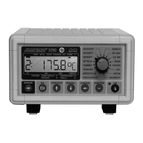
Ahlborn Almemo 8990-8 User manual

Operating Instructions
Data Logger
ALMEMO®8990-8
V1.3
03.02.2004

Operating Instructions
Data Logger
ALMEMO®8990-8
For reference with the ALMEMO®Manual
Table of Contents
Page
1 Introduction 2
1.1 Function Range 2
1.2 Operating Controls 6
2 Initial Operation 8
3 Power Supply 9
3.1 Mains Supply 9
3.2 Operation with Rechargeable Battery 9
3.3 External Power Supply 9
3.4 Battery Buffer 9
3.5 Switch On/Off, Reinitialisation 10
4 Connection of the Transducers 10
4.1 Transducers 10
4.2 Measuring Inputs and Additional Channels 11
5. Data Acquisition 12
5.1 Manual Measuring Point Scan 12
5.2 Cyclic Measuring Point Scan 12
5.3 Data Memory 13
5.4 Sleep Mode 14
5.5 Device Address and Networking 14
6 Troubleshooting 15
7 Electromagnetic Compatibility 16
Appendix
Technical Data
Product Overview
2 ALMEMO®8990-8
Table of Contents

1. INTRODUCTION
The new data logger ALMEMO®8990-8
Version 5
is an instrument from the
unique product range of measuring devices that are all equipped with the
ALMEMO®connector system, which has been patented by Ahlborn GmbH. The
intelligent ALMEMO®connector provides important advantages with regard to
the connection of sensors and peripherals as all parameters are stored in an
EEPROM within the connector. As a result, the programming that usually has
to be performed for the connection is not required.
All sensors and output modules can be connected to all ALMEMO®measuring
devices in the same way. The operation and programming is identical with all
units. Therefore, all of the ALMEMO®measuring system items listed below are
described, in detail, in a separate ALMEMO®manual that is supplied with every
device:
Detailed description of the ALMEMO®system (manual section 1)
Overview of the device functions and measuring ranges (manual section 2)
All sensors with basic principles, operation, technical data (man. section 3)
The options for connecting existing sensors (manual section 4)
All analogue and digital output modules (manual section 5.1)
The interface module RS232, fiber optics, Centronics (manual section 5.2)
The entire ALMEMO®networking system (manual section 5.3)
All functions and their control via the interface (manual section 6)
A complete interface command list with all print outputs (manual section 7)
These operating instructions, therefore, only cover features and controls that
are specific for a certain device. As a result, the sections dealing with the
system control via keyboard will only often provide a note referring to a more
detailed description within the manual (manual section x.x.x).
1.1 Function Range
The ALMEMO®8990-8 data logger has nine electrically isolated measuring
inputs with up to 36 measuring channels, a real time clock and a 512kB
memory for approximately 100,000 measured values. Two output sockets
allow for connecting any ALMEMO®output modules, for example, the analogue
output, digital interface, trigger input or alarm contacts. Several devices can be
networked by a simple connection between the devices. Three keys and the
serial interface are used for operating the instrument.
SENSOR PROGRAMMING
The measuring channels are automatically programmed by the ALMEMO®
connectors of the sensors. However, the user can easily complete or modify
the programming via interface without affecting the measuring process.
Functions
ALMEMO®8990-8 3

Measuring Ranges
There are corresponding measuring ranges for sensors with a non-linear
characteristic such as 10 thermocouple types, Ntc and Pt100 sensors, infrared
sensors, and flow sensors (rotating vanes, thermoanemometers, pitot tubes).
Humidity sensors are available with function channels that also calculate
humidity data such as dew point, mixture ratio, vapour pressure and enthalpy.
Even complex chemical sensors can be used. The acquisition of measured
data from other sensors is easily possible by using voltage, current and
resistance ranges with individual scaling in the connector. Existing sensors can
be used without problems. Only the corresponding ALMEMO®connector has to
be connected using its terminals. Furthermore, there are adapter connectors
with an own microcontroller for digital signals and for measuring frequencies
and pulses. This way, nearly all sensors can be connected to any ALMEMO®
measuring instrument and are interchangeable without requiring any settings.
Function Channels
Maximum, minimum, average values and differences of certain measuring
junctions can be programmed as function channels and can be processed and
printed like normal measuring junctions. Furthermore, function channels for
special measuring tasks are provided to determine temperature coefficient
Q/∆t and wet bulb globe temperatures.
Dimension
The 2 digit dimension can be altered for each measuring channel so that the
display and the printout will always indicate the correct dimension, for example
when a transmitter is connected. The conversion from °C to °F is automatically
performed according to the dimension.
Name of Measured Values
Sensors can be identified by a 10 digit alphanumeric designation. It is entered
via the interface and appears on the printout or display if the evaluation is done
via PC.
Correction of Measured Values
For correcting measured values a zero point and slope (gain) correction can be
applied to the measured value of each measuring channel. This also allows for
sensors to be interchanged that usually, at first, require an adjustment
(expansion, force, pH).
Scaling
The base value and the factor allow for a further scaling of the corrected
measured value of each measuring channel for zero point and slope (gain).
The decimal point position can be set by the exponent.
4 ALMEMO®8990-8
Functions

Limit Values and Alarm
Two limit values (1 max and 1 min) can be set for each measuring channel. An
alarm value printout can be performed if a limit value is exceeded and, by
means of relay output modules, alarm contacts are provided that can be
individually allocated to limit values. As a standard, the hysteresis is set to 10
digits, however, it can also be adjusted. Furthermore, limit value exceeding can
also be used to start or stop a measurement.
Sensor Locking
All sensor data stored in the EEPROM of the connector can be protected
against undesired access by means of a graded locking function.
MEASUREMENT
A total of up to 36 measuring channels are available for 9 transducers, i.e. it is
also possible to evaluate double sensors, individually scaled sensors, or
sensors with function channels. The selected measuring point can be scanned
with a conversion rate of 2.5 or 10 measurements/second. The measured
value is calculated and provided on the analogue output, if it is available.
Measured Value
A continuous presentation of measuring data from the selected measuring
point is provided and also includes automatic zero point correction and optional
correction of the measured value or new scaling. Sensor breakage recognition,
exception: current measurements.
Analogue Output and Scaling
By means of analogue start and analogue end the indicated measured value
can be scaled so that the resulting measuring range covers the full analogue
output range (2V, 10V or 20mA).
Measuring Functions
Special measuring functions are required for some sensors in order to achieve
an optimal acquisition of measuring data. A cold junction compensation is
performed at thermocouples. A temperature compensation is performed at
dynamic pressure and pH and conductivity probes and an atmospheric air
pressure compensation is performed at humidity sensors and O2sensors. With
infrared sensors the parameters zero point and slope correction are used for
background temperature and emissivity factor.
Maximum and Minimum Value
Each measurement involves an acquisition and storing of the maximum and
minimum value. These values can be displayed, printed or cleared.
Functions
ALMEMO8990-8 5

PROCESS FLOW PROGRAMMING
A cyclic measuring point scan with a time-based process flow control is
required to register the measuring data of all connected sensors. For this
purpose, the real time clock, the print cycle and the measuring cycle are
available and, if fast processing is required, the conversion rate is available.
The measurement can be started and stopped by using the keyboard, the
interface, an external trigger signal, the real time clock or an exceeding of limit
values.
Time and Date
The real time clock with date function or the pure measuring time are used for
an accurate recording of any measurement. Start and end time/date can be
programmed in order to start or stop a measurement.
Print Cycle
The print cycle is programmable between 1s and 59h/59min/59s and provides
a cyclic output of measured values to the interfaces or memories and also
provides a cyclic averaging.
Print Cycle Factor
If necessary, the print cycle factor allows for limiting the data output of
particular channels so that an excessive data flow can be limited, especially
during data storage.
Measuring Cycle
The measuring cycle, also programmable between 1s and 59h/59min/59s, is
for a cyclic scanning with a display of all measured values, limit value
monitoring including alarm message and output of alarm values, averaging
and, if necessary, a storage of measured values.
Average Value
The measured values resulting from scanning the measuring junctions can be
averaged as desired either over the total measuring time or over the print cycle
time. Function channels are provided for a cyclic output of average values.
Conversion Rate
With ALMEMO®
V5
devices, all measuring points can be continuously
scanned with the conversion rate (2.5 or 10 meas./s). It is possible to store all
measured values in the memory and/or to perform an output via the interface.
Data Memory
The measured values of any measuring point scans or just the alarm values
can be stored in a buffered RAM. The memory capacity is, as standard, 500kB,
which allows up to 100,000 measured values. The memory organisation can
be configured as linear or ring memory. The output can be optionally
performed via interface or the analogue output, if available. With digital outputs
it is possible to select a certain time interval, number or alarm value.
6 ALMEMO®8990-8
Functions

Numbering of Measurements
Single scans or entire series of measurements can be identified and selectively
read out from the memory.
Control Outputs
The interface allows to individually trigger up to four output relays and one
analogue output.
Keyboard Lock
The keyboard operation can be locked with a password.
Output
All data logs, measured values and programmed parameters can be provided
as output to any peripheral equipment via interface. Interface cables for
RS232, RS422, RS485 or Centronics interfaces are available. The output of
measuring data can be selected in list format, columns or spreadsheet format.
Files in spreadsheet format can be processed by each spreadsheet software.
The print header can be programmed specifically to the company or
application.
Networking
All ALMEMO®devices can be addressed and can be easily networked by a
simple connection with network cables or network junctions for longer
distances.
Software
The AMR-Control software, which allows for the entire programming of the
sensors, the configuration of the measuring instrument and the read-out of the
data memory is supplied with each ALMEMO®manual. The integrated terminal
also allows for online measurements. The WINDOWS®software packages,
Win-Control and DATA-Control, are available for data acquisition of networked
devices, graphical presentation and complex data processing. The software
LogCel is provided for an online import of data into MS-Excel®.
OPTION Rechargeable Battery
The data logger becomes completely self-sufficient with the option
'rechargeable battery'. Due to the power saving sleep mode, the measuring
instrument can, independent from mains supply, record measuring data for
weeks. Afterwards the rechargeable battery can be fully recharged within 2
hours by means of a power supply.
ALMEMO8990-8 7
Functions

1.2 Operating Controls
(1) ON/OFF SWITCH Instr. Lamp
not pressed OFF off
pressed with pow. supp.: ON on
Rechargeable
battery optional: with pow. supp.: ON on (batt. is recharging)
ON flashing (batt. is recharged)
without pow. supp.: ON off (battery operation active)
(2) CONNECTOR SOCKET
U-DC mains adapter ZA 5090-NA2 12V, 800mA
connector cable ZB 5090-EK 7-13V DC
connector cable ZB 3090-UK 10-30V DC
electr. isolated including DC/DC converter
(3) MEASURING INPUTS
0 to 8 for all sensors with an ALMEMO®connector
10 to 18 (38) add. channels for double sensors, funct. chann.
8 ALMEMO®8990-8
Operating Controls

(4) OUTPUTS
A1 V24 interface cable (ZA 1909-DK),
V24 fiber optic cable (ZA 1909-DKL)
RS 422 network branch box (ZA 5099-NVB)
RS 485 network branch box (ZA 5085-NV)
Centronics interface cable (ZA 1936-DK)
A1 or A2 analogue output with cable (ZA 1601-RK)
A2 networking with network cable (ZA1999-NK)
trigger input with cable (ZA 1000-EK/ET),
2 relay outputs with cable (ZA 1000-EGK/EAK)
(5) CODING SWITCH setting of the device address
module number 0 to 9, external access
2nd coding switch for decades
internal on the board
(6) FUNCTION KEYS
START start automatic measuring point scan
STOP and START start automatic meas. point scan in sleep mode
STOP stop automatic measuring point scan
OUTPUT memory output to interface
STOP and OUTPUT clear memory
(7) CONTROL LAMPS
CYCLE start automatic measuring point scan
ALARM exceeding of limit value or sensor breakage
MEMORY measuring point scan with storing
memory output to interface
Operating Controls
ALMEMO8990-8 9

2. INITIAL OPERATION
1. Connect transducers to the sockets 0 to 8 (3), see 4.
2. For power supply connect the mains adapter to socket U-DC (2), see 3.
3. For switching on press the ON/OFF push button (1), see 3.5.
4. Output of measuring data to printer or computer
Connect peripheral device via interface cable to socket A1, see man. 5.2.
Set 9600 bd, 8 data bits, 1 stop bit, no parity at peripheral device.
Enter time and date, as required, see manual 6.2.8.
Start manual measuring point scan by using the key START, see 5.1.
Program print cycle, output chann. and output format,
see man. 6.2.2/6.5.2/6.5.5.
Start automatic measuring point scan with the key START and stop it with
the key STOP, see 5.2.
5. Storing of measured values
Clear memory by using the keys STOP and OUTPUT, see 5.3.
Activate storing in measuring cycle, see manual 6.5.3.
Manual storing without cycle by using the key START, see 5.1.
Enter measuring cycle for cyclic storing, see manual 6.5.3.
Enter time and date of start and end of measurement, if required,
see man. 6.6.2.
Start automatic storing with the key START, see 5.2.
For long-term recording (cycle > 1min.), start automatic storing in sleep
mode by using the keys STOP and START, see 5.4.
Stop sleep mode by switching the instrument off and on.
Stop the automatic storing by using the key STOP, see 5.2.
Output of memory data to printer or computer
Connect peripheral device via interface cable to socket A1, see manual 5.2.
Set 9600 bd, 8 data bits, 1 stop bit, no parity at peripheral device.
Set output format list, column or spreadsheet (table), see man. 6.5.5.
Perform read-out of memory by using the key OUTPUT, see 5.3.
6. Monitoring of limit values
Enter limit values, see manual 6.3.9.
Program measuring cycle, see manual 6.5.3.
Connect alarm device with alarm module to socket A2, see man. 5.1.2/5.1.3.
Start automatic measuring point scan by using the key START and stop it by
using the key STOP, see 5.2.
10 ALMEMO®8990-8
Initial Operation
3. POWER SUPPLY
3.1 Mains Operation
The mains adapter ZB 5090-NA2 (12V DC, 800mA) is used for the power
supply to the instrument. It is connected to the socket U-DC (2) and is locked
by turning it to the right.
3.2 Operation with Rechargeable Battery (Option A)
With the option A, a NiCd rechargeable battery with 1.5 Ah will be installed,
which allows, at a current consumption of approximately 15mA, an
uninterrupted operating time of 100 hours at minimum. The operating time will
be shorter when sensors are connected that require additional current (e.g.
humidity sensors FH A646 2mA or rotating vanes approximately 3mA) or the
serial interface (4mA). However, the sleep mode is meant for a long term
operation of the data logger. It allows for a measurement of approximately
30000 measuring cycles. An exact determination of the voltage of the
rechargeable battery and an estimation of the remaining operating time is
available with the measuring channel ´Batt´.
The supplied mains adapter ZB 5090-NA2 allows to recharge a discharged
battery within 2 hours. During the recharge process the green lamp of the
on/off switch (1) is continuously illuminated. If the green lamp flashes, the
battery is completely recharged and the charge circuit is switched to trickle
charging. As a result, the power supply can, during buffer operation, remain
connected to the measuring instrument.
3.3 External Voltage Supply
It is also possible to connect another DC voltage 7...13V to the socket U-DC
(2). The cable ZB 5090-EK, fitted with 2 banana plugs, is available for the
connection. However, the electrically isolated supply cable ZA 3090-UK must
be used if an electrical isolation between power supply and transducers is
required or if a larger input voltage range 10...36V is required. It allows to
operate the measuring instrument with 12V or 24V mains supply.
3.4 Battery Buffer
For an uninterrupted power supply of the real time clock and the memory a
NiCd rechargeable battery (2.4V) for buffering is installed, which ensures that
time and date data and all stored values are maintained for several months if
the mains supply is not available or if the rechargeable battery is discharged.
However, to prevent the rechargeable battery from completely discharging and
to avoid the loss of data, the instrument be operated with mains supply for a
few hours should at least once per month.
Power Supply
ALMEMO8990-8 11

3.5 Switch On/Off, Reinitialisation
For switching on the instrument, the ON/OFF push button (1) must be
pressed. If the power supply unit is properly connected the green control lamp
in the push button will be illuminated.
The device can be switched off by operating the push button once again. The
control lamp will no longer be illuminated (not with option A, see 3.2). However,
the real time clock continues operating and, due to the buffering rechargeable
battery, all stored values remain available (see 3.5).
If the device shows an irregular behaviour due to interference influences (e.g.
electrostatic charging or discharged buffering battery) or if incorrect
programming must be avoided, the device can be completely reinitialised.
The reset can be achieved if the key STOP is pressed during switch-on. All
internal data such as max, min and average values, and the data memory will
be cleared. Furthermore, cycles, time, date and device address are set to zero
and the conversion rate and atmospheric pressure will be set to their default
setting. However, the device configuration and the sensor programming within
the ALMEMO®connectors will not be affected by the reset.
4. CONNECTION OF THE TRANSDUCERS
Any ALMEMO®sensors can be connected to the ALMEMO®input sockets 0 to
8 of the measuring instrument (3). For connecting existing sensors it is only
necessary to connect a corresponding ALMEMO®connector.
4.1 Transducers
A detailed description of the comprehensive ALMEMO®sensor range (see
manual section 3) and the connection of existing sensors (see manual section
4) to the ALMEMO®instruments are provided in the ALMEMO®manual. All
standard sensors with ALMEMO®connector usually have the measuring range
and dimension already programmed and can be immediately connected to any
input socket. A mechanical coding ensures that sensor and output modules
can only be connected to the correct sockets. Furthermore, each ALMEMO®
connector has two locking levers that snap in when the insertion into the socket
is established and that prevent a disconnection caused by pulling the cable.
Both levers must be pressed on the sides for disconnecting the connector.
The programming of the sensor connectors can, with ALMEMO8990-8
data loggers, only be modified by using the serial interface (see manual section
6). This can be carried out by using the PC and the configuration software
AMR-Control or any terminal application (e.g. Windows Terminal) and using
very easy commands. Due to the data storage within the connector, it is also
possible to perform the programming with hand-held instruments of the series
12 ALMEMO®8990-8
Connection of the Transducers

ALMEMO2290 via keyboard. The sensor connector must be connected to
the selected channel. When programming, it must be considered that
factory-programmed parameters are, by a locking mode, protected against
unintentional modification and that the locking level must first be reduced
before desired changes can be performed (see manual 6.3.12). The
connectors ZA 9000-FS are not locked and are, therefore, most suitable for
programming by the user.
4.2 Measuring Inputs and Additional Channels
The data logger ALMEMO®8990-8 has 9 input sockets that the measuring
channels 0 to 8 are initially allocated to. However, ALMEMO®sensors can, if
required, provide up to 4 channels so that 36 channels are available with 9
input sockets. The additional channels can be especially used with humidity
sensors with 4 measuring variables (temperature/humidity/dew point/mixture
ratio) or used for function channels. If required, the sensor can also be
programmed with several ranges or scalings or, depending on the pin
assignment, 2 or 3 sensors can be combined in one connector (e.g. TE/Ntc,
mV/V, mA/V etc.). The additional measuring channels of a connector are
increased in steps of 10 (e.g. the first sensor has the channels 00, 10, 20, 30,
the second sensor has the channels 01, 11, 21, 31 etc.).
The 9 analogue inputs are electrically isolated by using
photovoltaic relays and a potential difference of 50V DC / 60V
AC, at maximum, is permissible between them. However,
sensors combined within one connector and sensors with an
own power supply are electrically connected to each other and
must, therefore, be operated in isolation.The voltage applied to
the measuring inputs must not exceed ±5V (between B,C,D
and A or - respectively).
The cold junction compensation for thermocouple measurement is integrated
in socket 3 of the device.
00 01 0502 0603 0704 08
10 11 1512 1613 1714 18
20 21 2522 2623 2724 28
30 31 3532 3633 3734 38
chann. 1
chann. 2
chann. 3
chann. 4
01 5263748
A2 A1
Transducers
ALMEMO®8990-8 13

5. DATA ACQUISITION
The instrument ALMEMO®8990-8 provides the following options for the
acquisition of measuring data:
1. Continuous measurement of a selectable measuring point, see manual 6.4
Possibly, an output of measuring data to an analogue output, see man. 5.1.1
2. Single measuring point scan, see manual 6.5.1.1.
3. Cyclic measuring point scan, see manual 6.5.1.2.
4. Continuous measuring point scan, see manual 6.5.1.3.
Previous measuring data should be cleared before a measurement.
A total clearing of all measured values, i.e. the clearing of max, min and
average values of all channels, as well as the clearing of the memory is
performed by pressing the keys STOP and OUTPUT. For automatic clearing
during start, see manual 6.10.13.2.
The programming of the process control is performed via serial interface
and by using the configuration software AMR-Control or a terminal (PC) (see
manual section 6). If during programming a programming connector (ZA
8990-PS) is connected to the socket A2 all parameters will be transmitted to
the connector. If such a connector is also connected to socket A2 during
switch-on, the data will be reloaded and the instrument will be programmed
correspondingly. By using several connectors the configuration can be easily
changed. If a programming via interface is not required the connectors can be
ordered factory-programmed to customer specifications.
5.1 Single Measuring Point Scan
If no measuring point scan has been set, only the measured value of the
selected measuring point, beginning with measuring point 0, will be
continuously acquired with the selected conversion rate (see manual 6.5.4).
This is the best possible operating mode for a data logging with analogue
output.
Measuring point scans can be used to acquire, indicate and document data
from the selected measuring point and also from other measuring points. As
long as no print cycle and no measuring cycle are programmed (e.g. after a
reinitialisation, see 3.5) only single measuring point scans are triggered by
using the key START. The control lamp ´CYCLE´ is only illuminated during the
data query and will then turn off. If the time was cleared, it will be restarted, a
measuring point scan of all connected active sensors will be performed and the
measured values will, for one time, be provided as output to a connected
printer. If the memory is activated (see manual 6.5.3) the control lamp
´MEMORY´ will be on during the data query. With each press of the key the
measured values are equally processed with the corresponding measuring
time. If true time has to be indicated, it must first be set (see manual 6.2.8).
14 ALMEMO®8990-8
Data Acquisition

5.2 Cyclic Measuring Point Scan
A cyclic measuring point scan can be started by using the key START if a
measuring or print cycle has been programmed. The control lamp ´CYCLE´ will
be continuously on afterwards and the measured values will be provided as
output to a connected peripheral device. If the memory is active the measured
values will also be saved in cycles and, in addition, the control lamp
´MEMORY´ will be on.
The automatic measuring point scan can be stopped by operating the key
STOP. The control lamps ´CYCLE´ and ´MEMORY´ will turn off afterwards.
5.3 Data Memory
The setup of the data memory, the data acquisition and data output with the
data logger ALMEMO8990-8, are described in the manual section 6.9. The
easiest way is to program a measuring cycle including memory activation
and then start the cyclic measuring point scan by using the key START and
stop it by using the key STOP.
For an output of the data memory to the serial interface the peripheral
device must be connected (see manual 5.2), the output channel ´U´must be
set (manual 6.2.2) and an output format, ´List´, ´Column´ or ´Spreadsheet´
must be selected (manual 6.5.5, output logs, see manual 6.6.1).
For starting the memory output the key OUTPUT must be operated. During
the memory output the control lamp ´MEMORY´ is on. The contents of the
memory is provided with the selected output format, if necessary, several times
and also in different formats. The output can be interrupted at any time by
using the key STOP and afterwards can be continued by using the 3 keys
below:
OUTPUT manual outputs of single measuring point scans
START automatic output is resumed
STOP memory output is aborted
Clearing the Data Memory
While pressing and holding the key STOP operate the key OUTPUT.
Further functions of the data recording and output are also described, in detail,
in the ALMEMOmanual.
Starting and stopping the recording with respect to time, exceeding of limit
value or external triggering (see manual 6.6)
Selective data output with respect to time and date,
number of the measurement or alarm values only (see manual 6.9)
Continuous recording of one channel with 10 M/sec. (see manual 6.5.1.3)
Data Memory
ALMEMO8990-8 15

5.4 Sleep Mode
For long term monitoring with larger measuring cycles it is possible to operate
the instrument in sleep mode by using a rechargeable battery (option A) or an
external battery. Within this power saving mode the device will be switched off
after each measuring point scan and be automatically switched on for the next
scan after the cycle time has expired. This procedure allows, at a fully charged
battery to perform approx. 15,000 measuring point scans. At 5 minutes for one
cycle this results in a total measuring time of more than 50 days.
The following steps must be performed for an operation in sleep mode:
1. Enter a measuring or print cycle of a minimum of 2 minutes.
If both cycles are programmed the measuring cycle will be ignored.
2. For starting a measurement in sleep mode
the key START must be operated while holding the key STOP pressed.
The starting and stopping by the start and end time,
and also by the limit values, is generally not possible in sleep mode and
must, therefore, be switched off!
The instrument will be practically switched off after the first scan.
Within the set cycle the instrument will switch on, perform a measuring
point scan, the control lamps CYCLE and MEMORY will be illuminated for a
short time and the instrument will then switch off again.
3. Switch over to active operation: Switch the device off and on again.
4. Terminate the measurement by pressing the key STOP.
5.5 Device Address and Networking
As with all other ALMEMOinstruments, the data loggers ALMEMO8990-8
can also be networked. For communicating with networked devices it is
mandatory that each device has its own address as only one device is allowed
to respond to each command. Therefore, before any network operation it is
necessary that all connected devices are set to different device numbers. The
numbers 0 to 9 can be set using the coding switch (5) on the front panel. If
device addresses are required higher than 9, a second coding switch that is
mounted internally on the board can be used to set the decimal digit. For
setting the address it is necessary to loosen the 4 screws in the upper shell of
the housing and remove the shell.
Example:
Module Address 01
S2 S1
0
5
1
2
3
4
6
7
8
9
0
5
1
2
3
4
6
7
8
9
01
decimal digit
on board
inside the instr.
digits on
front panel
NUMBER
module address
16 ALMEMO®8990-8
Sleep Mode

6. TROUBLESHOOTING
The data logger ALMEMO®8990-8 can be configured and programmed in
many different ways. It allows for a connection of many different sensors,
additional measuring instruments, alarm signalisers and peripheral devices.
Therefore, it is possible that, under certain conditions, it does not perform as
the user would expect. In most cases this will not be related to a defective
device but to operating errors such as wrong settings or an inadmissible wiring.
The following tests should be performed to correct or to correctly identify the
error.
Error: Switch-on indicator is not illuminated or no LEDs are permanently on.
Remedy:Check power supply, recharge battery, switch off and on again,
reinitialise (see 3.5)
Error: False measured values.
Remedy:Thoroughly check the programming of the channel (AMR-Control),
query the entire programming by means of the command P15 (see
manual 6.2.3) and f1 P15 (see manual 6.10.1)
Error: Varying meas. values, cyclic measuring point scan blocked.
Remedy:Check cabling for inadmissible electrical connection,
disconnect all suspicious sensors,
hold hand-held sensors in air or connect dummies and check (short
circuit AB at thermocouples, 100Ωat Pt100 sensors), then reconnect
sensors successively and check. If an error occurs with one sensor,
check the wiring, isolate the sensor if necessary, prevent influences
from disturbances by shielding or twisting.
Error: Data transmission via interface does not function.
Remedy:Check interface module, connections and settings:
Are both devices set to the same baud rate and transmission mode
(see manual 6.10.12)?
Is the correct COM interface addressed at the computer?
Is the output channel set to "U" (see manual 6.2.2)?
Is the printer set to ONLINE mode?
Are the handshake lines DTR and DSR active?
A small interface tester with LEDs is very useful for checking the data flow
and the handshake lines (during standby mode the data lines TXD and RXD
are on a negative potential of approximately -9V and the diodes are
illuminated green. The handshake lines DSR, DTR, RTS and CTS have a
positive voltage of approximately +9V and the LEDs are illuminated red.
During the data transmission the data lines must flash red).
Troubleshooting
ALMEMO8990-8 17

Test the data transmission by using a terminal (AMR-Control,
WIN-Control, DATA-Control, WINDOWS Terminal):
Address the device with its device number Gxy (see manual 6.2.1),
internal coding switch must be considered for decimal address digits,
programming must be queried with command P15 (see man. 6.2.3),
sending line must be tested by single measuring point scan with s, if
at least one sensor is connected the LED ´CYCLE´ must be on,
receiving line must be tested by a memory output with key OUTPUT
Error: Data transmission within network does not function
Remedy:Check that all devices are set to different addresses,
address devices individually via terminal and command Gxy,
addressed device is OK when the feedback is at least y CR LF.
If data transmission is still not possible, disconnect networked
devices, check devices separately at data cable of the computer,
check the wiring regarding short circuit or twisting.
Are all network distributors supplied with power?
Network and check the devices successively again (see above).
If the device is, after the above inspections, still not performing as specified in
the operating instructions, it must be sent to the factory in Holzkirchen,
Germany, including a short report and possibly control printouts. The software
AMR-Control allows to print the monitor pages including the programming and
also to save the terminal operation and to print it out.
11. ELECTROMAGNETIC COMPATIBILITY
The data logger ALMEMO®8990-8 meets the electromagnetic compatibility
(EMC) safety requirements specified in the relevant CE directive issued by the
council for the alignment of legal regulations of the member states
(89/336/EWG).
The following standards have been applied for the evaluation of the product:
IEC 61326:1997+A1:1998+A2:2000
IEC 61000-6-1:1997 IEC 61000-6-3:1996
IEC 61000-4-2: 1995+A1:1998+A2:2000 8kV IEC 61000-4-4: 1995+A1:2000 2kV
IEC 61000-4-3: 1995+A1:1998+A2:2000 3V/m
The following notes must be observed when operating the instrument:
1. If the standard sensor cables (1.5m) are extended it must be considered that the
measuring lines are not guided together with power mains and that they are
appropriately shielded to protect against any coupling of disturbance signals.
2. If the instrument is operated within strong electromagnetic fields an additional
measuring error must be expected (<50µV at 3V/m and 1.5m thermocouple
transducers). After the irradiation the device operates again within the specified
technical data.
18 ALMEMO®8990-8
Electromagnetic Compatibility

Technical Data (see also Section 2.2 in Manual)
Measuring Inputs: 9 ALMEMO®sockets for ALMEMO®connector
Meas. channels: 9 primary chann. electr. isol., max. 27 addit. chann.
for double sensors and function channels
Sensor voltage supply: mains adapter: approx 12V, max. 100mA
rechargeable battery: 7...9V, max. 100mA
Outputs: 2 ALMEMO®sockets for all output modules
Equipment:
Keyboard: 3 keys
Memory: 500 kB (100000 meas.val.) buff. w. rechar. NiCd batt.
Time and date: real time clock buff. with rechargeable Lithium battery
Microprocessor: HD 6303 Y
Voltage Supply: 7 to 13V DC not electrically isolated
Mains adapter: ZB 5090-NA2 230VAC to 12VDC, 0.8A electr. isol.
Adapter cable electr. isol.: ZB 3090-UK 9...30V DC to 12V DC, 250mA
Option A: NiCd recharg. batt. 7.2V, 1.6Ah
Time for recharging: ca. 2h, quick and trickle charge
Current consumption without active mode: approx. 15mA
input and output modules: sleep mode: approx. 10µA
Housing: metal housing H63 x W144 x D219mm (3HU, 6DU)
Operating temperature: -10 ... +60 °C
Storage temperature: -30 ... +60 °C
Humidity of ambient air: 10 ... 90% rH non-condensing
Extent of the Delivery: Measuring Instrument ALMEMO®8990-8
Mains Adapter ZB 5090-NA2 12V/ 800mA
Operating Instructions ALMEMO®8990-8
ALMEMO®Manual incl. software AMR-Control
Product Overview Order No.
Data Logger ALMEMO®8990-8
9 inputs, 36 channels at maximum, 500 kB memory,
real time clock, 3 keys, RS232 interface that can be cascaded,
sleep mode, mains adapter 12V / 0.8A MA 8990-8
Option A Instr. incl. recharg. batt. 7.2V, 1.6Ah, quick charge within 2h OA 8990-A
ALMEMO®Programming Connector for process control configuration ZA 8990-PS
DC Adapter Cable 10 to 30V DC, 12V/250mA electr. isol. ZB 3090-UK
ALMEMO®Recording Cable -1.25 to 2.00 V, 0.1 mV/digit ZA 1601-RK
ALMEMO®Data Cable V24 Interface, electr. isolated ZA 1909-DK
ALMEMO®Data Cable Centronics Interface, electr. isolated ZA 1936-DK
ALMEMO®Network Cable Current Loop, electr. isolated ZA 1999-NK
ALMEMO®I/O Cable for Triggering and Limit Value Alarm ZA 1000-EGK
ALMEMO8990-8 19
Appendix

20 ALMEMO®8990-8
Appendix
Table of contents
Other Ahlborn Data Logger manuals

Ahlborn
Ahlborn ALMEMO 2890-9 User manual

Ahlborn
Ahlborn ALMEMO 500 User manual

Ahlborn
Ahlborn ALMEMO 500 User manual

Ahlborn
Ahlborn ALMEMO 2690-8A User manual

Ahlborn
Ahlborn ALMEMO 2590-9 V5 User manual

Ahlborn
Ahlborn ALMEMO 500 User manual

Ahlborn
Ahlborn ALMEMO 2690-8 User manual

Ahlborn
Ahlborn ALMEMO 2290-8 User manual

Ahlborn
Ahlborn ALMEMO 470 User manual

Ahlborn
Ahlborn ALMEMO 2690-8A User manual