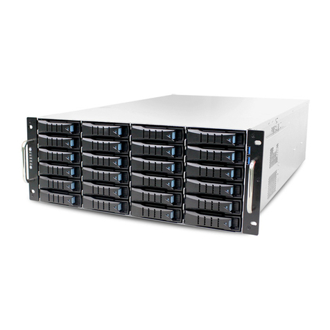
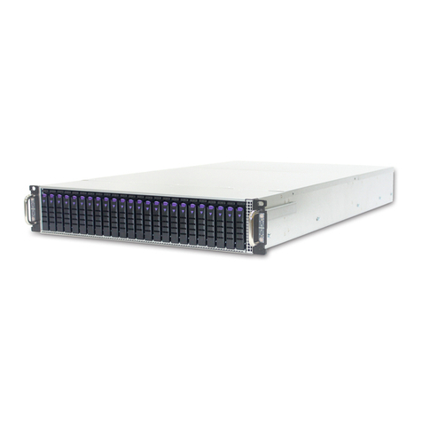
AIC SB402-CP2 User manual

SB402-CP2
Storage Server Barebone
User Manual
Document Number: MAN-00113-A
P/N: H884BC9002-00001-0

1
Contents
SAFETY INFORMATION ................................................................................. 4
ABOUT THIS USER MANUAL......................................................................... 5
CHAPTER 1. PRODUCT INTRODUCTION...................................................... 6
1.1 General Information............................................................................... 6
1.2 System Specifications ........................................................................... 7
1.3 Front View of SB402-CP2..................................................................... 9
1.4 Rear View of SB402-CP2...................................................................... 9
1.5 Top View of SB402-CP2 ..................................................................... 10
CHAPTER 2. HARDWARE SETUP................................................................ 11
2.1 Chassis Cover...................................................................................... 11
2.2 Central Processing Unit (CPU)........................................................... 11
2.2.1 Installing the CPU ................................................................. 12
2.2.2 Installing the CPU Heatsink................................................. 14
2.2.3 Diagram of the Correct Installation ..................................... 15
2.3 System Memory ................................................................................... 16
2.3.1 Supported Memory ............................................................... 16
2.3.2 Memory Population Rules.................................................... 17
2.3.3 Publishing System Memory ................................................. 19
2.4 Drive Bays............................................................................................. 20
2.4.1 Installing or Replacing 3.5” Hot-swap SAS/SATA HDD ... 20
2.5 System Fans......................................................................................... 21
2.5.1 Removing or Replacing the Upper Level System Fans.... 21
2.5.2 Removing or Replacing the Lower Level System Fans.... 21
2.6 Power Supply........................................................................................ 22
2.6.1 Removing or Replacing the Power Supply Module........... 22
CHAPTER 3. MOTHERBOARD SETTINGS .................................................. 23
3.1 Motherboard Layout............................................................................. 23
3.2 Motherboard block diagram................................................................ 24
3.3 Internal Connectors.............................................................................. 24

2
3.4 Intel® Server Board S2600CP Jumper Blocks................................. 26
3.5 Rear I/O Layout.................................................................................... 27
CHAPTER 4. INTEL® SERVER BOARD S2600CP PLATFORM
MANAGEMENT ............................................................................................. 28
4.1Server Management Function Architecture....................................... 28
4.1.1 Feature Support.................................................................... 28
4.1.2 Basic and Advanced Features............................................. 31
4.1.3 Integrated BMC Hardware: Emulex* Pilot III...................... 31
4.2 Server Management Functional Specifications................................ 34
4.2.1 BMC Internal Timestamp Clock........................................... 34
4.2.2 System Event Log (SEL)...................................................... 34
4.2.3 Field Replaceable Unit (FRU) Inventory Device................ 35
4.2.4 BMC Beep Codes ................................................................. 35
4.2.5 Diagnostic Interrupt (NMI) Button........................................ 36
4.2.6 BMC Watchdog..................................................................... 36
4.3 Sensor Monitoring................................................................................ 37
4.3.1 Overview................................................................................ 37
4.3.2 Core Sensors......................................................................... 37
4.3.3 BMC System Management Health Monitoring .................. 39
4.3.4 Processor Sensors................................................................ 39
4.3.5 Thermal and Acoustic Management................................... 39
4.3.6 Thermal Sensor Input to Fan Speed Control..................... 41
4.3.7 Power Supply Status\Health Sensors................................. 42
4.3.8 System Event Sensor........................................................... 44
4.4 Channel Management......................................................................... 44
4.4.1 Channel Management.......................................................... 45
4.4.2 User Model............................................................................. 45
4.4.3 LAN Interface......................................................................... 45
4.5 Advanced Management Feature Support......................................... 55
4.5.1 Enabling Advanced Management Features....................... 55

3
4.5.2 Keyboard, Video, Mouse (KVM) Redirection..................... 56
4.6 Intel® Intelligent Power Node Manager (NM)................................... 57
4.6.1 Hardware Requirements ...................................................... 58
4.6.2 Features................................................................................. 58
4.6.3 ME Firmware Update............................................................ 58
4.6.4 SmaRT/CLST........................................................................ 59
4.7 EU Lot 6 Mode...................................................................................... 59
4.7.1 Impact to System Features.................................................. 60
CHAPTER 5. TECHNICAL SUPPORT....................................................... 61
Copyright © 2013 AIC, Inc. All Rights Reserved.
This document contains proprietary information about AIC
products and is not to be disclosed or used except in
accordance with applicable agreements.

4
Safety Information
When installing, operating, or performing maintenance on this equipment, the following safety
precautions should always be followed to reduce the risk of fire, electric shock, and personal injuries.
Read and understand all instructions.
Observe warnings and instructions marked on the product.
For proper mounting instructions, please consult the User‟s Manual provided with this
product.
Do NOT place this product on an unstable cart, stand, table or uneven surface that might
cause the product to fall and sustain serious damage.
Only install the equipment identified in the User‟s Manual. Use of other equipment could
cause improper connection of circuitry and may result in fire or personal injury.
This product should only be operated with the type of power source indicated on the
marked label. If you are uncertain about which type of power supply is used in your area,
consult your dealer or local Power Company.
Disconnect the power supply module before removing power from the system.
Unplug this product from the wall outlet before cleaning. Use a damp cloth for cleaning.
Do not use liquid cleaners or aerosol cleaners.
Do not use this product near a water source, such as a faucet.
Never spill liquids of any kind on this product.
Never shove objects of any kind into this product‟s open slots, as they may touch
dangerous voltage points or short out parts and could result in fire or electric shock.
Do not block or cover slots and openings in this unit, as they were made for ventilation
and prevent this unit from overheating. Do not place this product in a built-in installation
unless proper ventilation is available.
Do not disassemble this product. This product should only be taken apart by trained
personnel. Opening or removing covers and circuit boards may expose you to electric
shock or other risks. Incorrect reassembly can also cause electric shock when the unit is
subsequently used.
Risk of explosion is possible if battery is replaced with an incompatible type. Dispose of
used batteries accordingly.
This product is equipped with a three-wire grounding type plug, a plug with a third
(grounding) pin. As a safety feature, this plug is intended to fit only into a grounding type
power outlet. If you are unable to insert the plug into the outlet, contact your electrician to
replace the outlet. Do not remove the grounding type plug or use a 3-Prong To 2-Prong
Adapter to circumvent the safety feature; doing so may result in electric shock and/or
damage to this product.

5
About This User Manual
This document provides a detailed description of the SB402-CP2 including:
General Features of the Product
Hardware Setup
Motherboard Settings
BIOS Configuration and Settings
BMC Configuration and Settings

6
Chapter 1. Product Introduction
1.1 General Information
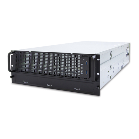
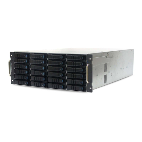
SB402-CP2, a 4U Storage Server Barebone, supports two Intel®Xeon®processors E5-2600/E5-2600
v2 series. SB402-CP2 has 36 x 3.5” in the front and 2 x 2.5” size HDD bays in the rear side as system
drive bays. It is a perfect building block for Storage Servers.
System Package Contents
Check your package for the following items:
Motherboard
Intel® Server Board S2600CP2
Components
1 x 1100W 1+1 Hot-swap Redundant Power Supply
36 x Hot-Swap 3.5” HDD Trays
2 x Internal 2.5” HDD Trays
3 x System Fans
Accessories
2 x Power Cords
2 x Internal SATA Cables
1 x 28” Rail (28” inner; 26” outer)
2 x Heatsinks

7
1.2 System Specifications
Dimensions (including chassis ears/protrusions)
W x D x H
mm : 483 X 679 X 173.5
inches : 19 X 26.7 X 7
Motherboard
Intel® Server Board S2600CP2
Processor
▪Dual LGA 2011 (Socket –R)
▪Supports two Intel® 2S Xeon® E5-2600/E5-2600 v2 Processors
▪Thermal Design Power up to 135-W
Chipset
Intel® C602 series chipset
System Memory
▪16 x memory slots (2 slots per channel)
▪Support for 800/1066/1333/1600 MHz/s Registered DDR3 Memory (RDIMM),
Unbuffered ECC DDR3 memory (UDIMM) and Load Reduced DDR3 memory
(LRDIMM)
▪Maximum memory size of 512 GB
Front Panel
Buttons
Power on/off and mute switch
Indicators
Power, 2 x LAN and HDD LEDs
Connectors
Type A USB 2.0 port
Drive Bays
▪Front: 24 x 3.5” hot-swap SATA/SAS HDD bays
▪Rear: 12 x 3.5” hot-swap drive bays
Expansion Slots
▪PCI slots
SATA/SAS Backplane
▪12 x 3.5” H-Tray SAS 6G B/P SGPIO single 28P-EXP on board
▪24 x 3.5” H-Tray SAS 6G B/P SGPIO single 28P-EXP on board
RAID Support
▪Intel® RSTe SW RAID 0/1/10/5
▪LSI® SW RAID 0/1/10
Video Support
Integrated Matrox G200 2D Graphics controller
LAN
2 x Gigabit network through Intel® I350 10/100/1000 Mb integrated MAC and PHY
controller
Internal I/O Connectors/ Headers
▪1 x 2x5 pin connector providing front panel support for 2 x USB ports
▪1 x internal Type-A USB 2.0 port
▪1 x internal USB port to support low profile eUSB SSD

8
▪1 x DH-10 serial Port B connector
▪1 x 1x7pin header for optional Intel® Local Control Panel support
Rear I/O
I/O
▪1 x DB-15 VGA output
▪1 x external DB9 serial port
▪2 x RJ-45 10/100/1000Mb ethernet ports
▪2 x USB 2.0 ports
Indicators
▪Diagnostics LED
▪ID LED
▪System Status LED
Power Supply
▪1100W AC 1+1 hot-swap redundant (Gold-Level) PSU
▪90-264 VAC, 47-63 Hz
System Cooling
Middle: 80x38 mm hot-swap fans
Server Management
▪Onboard Server Engines* LLC Pilot III* Controller
▪Support for Intel® Remote Management Module 4 solutions
▪Intel® Light-Guided Diagnostics on field replaceable units
▪Support for Intel® System Management Software
▪Support for Intel® Intelligent Power Node Manager (Need PMBus - compliant power
supply)
Operating Environment
▪Temperature: -10ºC ~ 60ºC (14ºF ~ 140ºF) for storage
0ºC ~ 35ºC (32ºF ~ 95ºF) for operating
▪Humidity: 5% ~ 95% non-condensing

9
1.3 Front View of SB402-CP2
LED
Icon
Color
System
Behavior
Controls
Icon
System Behavior
Power
LED
Green
Solid: System
On Off:
System Off
Power
ON/OFF
Push for Power
On or Off
LAN LED
Green
Light: Link
Blink: Activity
System
Reset
Push for System
Reset Non-
maskable
interrupt
HDD
LED
Green
Blink: Activity
USB 2.0
port
For USB device
connection
1.4 Rear View of SB402-CP2
LED
USB
PCIe SlotsI/O PortsPower Supply
3.5” HDD

10
1.5 Top View of SB402-CP2
3.5” HDD
PSU
3.5” HDD
easy swap
fans
Intel
S2600CP2 MB
Rear I/O

11
Chapter 2. Hardware Setup
This section illustrates the maintenance procedures for replacing a defective part once the SB402-
CP2 appliance is installed and operational.
2.1 Chassis Cover
2.1.1 Removing the Chassis Cover
1. Loosen screws on the rear side.
2. Slide the cover backwards to remove it from the chassis.
2.2 Central Processing Unit (CPU)
Caution: When unpacking a processor, hold the processor only by its edges to avoid
touching the contacts.
1
2

12
2.2.1 Installing the CPU
A. Open the Socket Lever
NOTE: Release the levers in the order as shown
1. Push down the lever handle on the OPEN 1st side and away from the socket
to release it.
2. Repeat the steps to release the lever on the other side.
B. Open the Load Plate
1. Press the locking lever slightly to raise the load plate. Open the load plate all
the way.

13
C. Install the Processor
Caution: The underside of the processor has components that may damage the socket
pins if installed improperly. Processor must align correctly with the socket opening
before installation. DO NOT DROP processor into the socket!
1. Take the processor out of the box and remove the protective shipping cover.
2. Orient the processor with the socket so that the processor cutouts match the
four orientation posts on the socket.
3. Note location of gold key at corner of processor.
Caution: When unpacking a processor, hold by the edges only to avoid touching the
gold contact.

14
2.2.2 Installing the CPU Heatsink
Caution: The heat sink has thermal interface material (TIM) on the underside of it.

Use caution so that you do not damage the thermal interface material. Use gloves to
avoid sharp edges.
1. Get heat sink from the shipping position.
2. Remove the protective film on the TIM if present.
3. Align heat sink fins to the front and back of the chassis for correct airflow. Airflow
goes from front-to-back of chassis.
The heat sink has four captive fasteners and should be tightened using the following
procedure:
4. Using a #2 screwdriver, finger-tighten each fastener diagonally as shown by the
numbers in the diagram below.
5. Securely re-tighten each fastener again in the same order as performed in Step
4.
Caution: Do not over-tighten fasteners.

15
2.2.3 Diagram of the Correct Installation
NOTE: The heat sink’s fans should be blowing toward the rear end of the chassis. If one of the fans is facing
the wrong direction, please remove the heat sink and reinstall it so that it is facing the correct direction.
AIRFLOW
AIRFLOW
FAN
FAN

16
2.3 System Memory
2.3.1 Supported Memory
UDIMM Support
Ranks Per
DIMM and
Data Width
Memory Capacity Per
DIMM
Speed (MT/s) and Voltage Validated by Slot per
Channel (SPC) and DIMM
Per Channel (DPC)
Intel® Server Board S2600CP (2 Slots per Channel)
1DPC
2DPC
1.35V
1.5V
1.35V
1.5V
SRx8 Non-
ECC
1GB
2GB
4GB
n/a
1066, 1333
n/a
1066, 1333
DRx8 Non-
ECC
2GB
4GB
8GB
n/a
1066, 1333
n/a
1066, 1333
SRx16 Non-
ECC
512MB
1GB
2GB
n/a
1066, 1333
n/a
1066, 1333
SRx8 ECC
1GB
2GB
4GB
1066,
1333
1066, 1333
1066
1066, 1333
DRx8 ECC
2GB
4GB
8GB
1066,
1333
1066, 1333
1066
1066, 1333
RDIMM Support
Ranks Per
DIMM and
Data Width
Memory Capacity Per
DIMM
Speed (MT/s) and Voltage Validated by Slot per
Channel (SPC) and DIMM
Per Channel (DPC)
Intel® Server Board S2600CP (2 Slots per
Channel)
1DPC
2DPC
1.35V
1.5V
1.35V
1.5V
SRx8
1GB
2GB
4GB
1066,
1333
1066, 1333,
1600
10,661,333
1066, 1333,
1600
DRx8
2GB
4GB
8GB
1066,
1333
1066, 1333,
1600
10,661,333
1066, 1333,
1600
SRx4
2GB
4GB
8GB
1066,
1333
1066, 1333,
1600
10,661,333
1066, 1333,
1600
DRx4
4GB
8GB
16GB
1066,
1333
1066, 1333,
1600
10,661,333
1066, 1333,
1600
QRx4
8GB
16GB
32GB
800
1066
800
800
QRx8
4GB
8GB
16GB
800
1066
800
800

17
LRDIMM Support
Ranks Per
DIMM and Data
Width
Memory Capacity
Per DIMM
Speed (MT/s) and Voltage Validated by Slot per
Channel (SPC) and DIMM
Per Channel (DPC)
Intel® Server Board S2600CP (2 Slots per Channel)
1DPC and 2DPC
1.35V
1.5V
QRx4
(DDP)
1GB
2GB
1066
1066, 1333
QRx8
(P)
2GB
4GB
1066
1066, 1333
2.3.2 Memory Population Rules
Each processor provides four banks of memory, with each bank capable of supporting up to 2
DIMMs.
DIMMs are organized into physical slots on DDR3 memory channels that belong to
processor sockets.
The memory channels from processor socket 1 are identified as Channel A, B, C and D.
The memory channels from processor socket 2 are identified as Channel E, F, G and H.
The silk screened DIMM slot identifiers on the board provide information about the
channel, and therefore the processor to which they belong. For example, DIMM_A1 is
the first slot on Channel A on processor 1, and DIMM_E1 is the first DIMM socket on
Channel E on processor 2.
The memory slots associated with a given processor are unavailable if the
corresponding processor socket is not populated.
A processor may be installed without populating the associated memory slots provided
that a second processor is installed with its associated memory. However, the memory is
shared by the processors in this case, and the platform suffers performance degradation
and latency due to the remote memory.
Processor sockets are self-contained and autonomous. However, all memory subsystem
supports (such as Memory RAS, Error Management) in the BIOS setup are applied
commonly across processor sockets.
On the Intel® Server Board S2600CP, a total of 16 DIMM slots are provided (2 CPUs –4
Channels/CPU, 2 DIMMs/Channel). The nomenclature for DIMM sockets is detailed in the
following table:
Processor Socket 1
Processor Socket 2
(0)
Channel A
(1)
Channel B
(2)
Channel C
(3)
Channel D
(0)
Channel E
(1)
Channel F
(2)
Channel G
(3)
Channel H
A1
A2
B1
B2
C1
C2
D1
D2
E1
E2
F1
F2
G1
G2
H1
H2

18
The following are common DIMM population requirements that generally apply to both Intel® Server
Board S2600CPs.
The “farthest fill first” rule must be followed when filling DIMM slots on any memory
channel.
A maximum of 8 ranks can be installed on any one channel (includes all ranks in each
DIMM on the channel).
Different DIMM types (UDIMM, RDIMM, and LRDIMM) must not be mixed within or
across processor sockets.
Mixing ECC with non-ECC DIMMs (UDIMMs) is not supported within or across processor
sockets.
Mixing Low Voltage (1.35V) DIMMs with Standard Voltage (1.5V) DIMMs is not supported
within or across processor sockets.
Mixing DIMMs of different frequencies and latencies is not supported within or across
processor sockets.
LRDIMM Rank Multiplication Mode and Direct Map Mode must not be mixed within or
across processor sockets.
Only ECC UDIMMs support Low Voltage 1.35V operation.
QR RDIMMs may only be installed in DIMM Slot 1 or 2 on a channel.

19
2 DPC QR Low Voltage RDIMMs are not supported.
In order to install 3 QR LRDIMMs on the same channel, they must be operated with Rank
Multiplication as RM = 2.
RAS Modes Lockstep, Rank Sparing, and Mirroring are mutually exclusive in this BIOS.
Only one operating mode may be selected at a time and will be applied to the entire
system.
If a RAS Mode has been configured and the memory population does not support it
during boot, the system will by default revert back to the Independent Channel Mode and
will also log and display errors.
Rank Sparing Mode is only possible when every single one of the channels populated
with memory either has at least 2 SR or DR DIMM installed or at least one QR DIMM
installed.
Lockstep or Mirroring Modes require that for any channel pair populated with memory, the
sizes of memory populations on both channels must be identical.
2.3.3 Publishing System Memory
The BIOS displays the “Total Memory” of the system during POST if Quiet Boot is disabled in the
BIOS setup. This is the total memory size discovered by the BIOS during POST and is the sum of
the individual sizes of installed DDR3 DIMMs in the system.
The BIOS displays the “Effective Memory” of the system in the BIOS setup. “Effective Memory”
refers to the total size of all DDR3 DIMMs that are both active (not disabled) and not used as
redundant units.
The BIOS displays the total memory of the system in the main page of the BIOS setup. This total is
the same as the “Total Memory” described by the first paragraph above.
If Quiet Boot is disabled, the BIOS displays the total system memory on the diagnostic screen at the
end of POST. This total is the same as the “Total Memory” described by the first paragraph above.
Table of contents
Other AIC Network Storage Server manuals