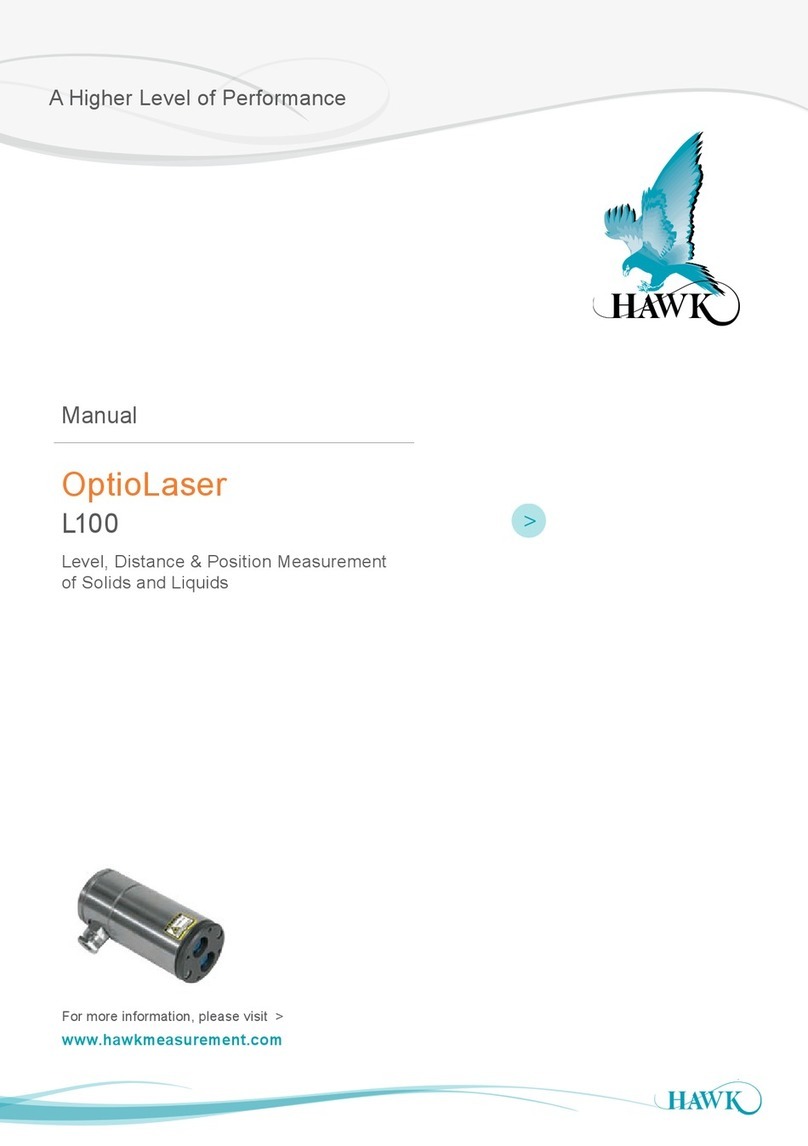
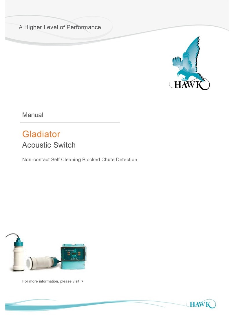
Hawk OptioLaser L200 User manual

Table of Contents
OptioLaser L200
2
Table Of Contents
Overview 3
Principle of Operation 3
Applications 3
Features 3
Quick Start Guide 4
Connections & Instructions for Safe Use
6
Connections & Instructions for Safe Use & Labels 7
Laser Radiation Information 7
Labels 7
Apendix A 8
Specifications 8
Apendix B 9
Dimension Drawings 9
Part Numbering 10
PROPRIETARY NOTICE
The information contained in this publication is derived in
part from proprietary and patent data. This information has
been prepared for the express purpose of assisting operating
and maintenance personnel in the efficient use of the
instrument described herein. Publication of this information
does not convey any rights to use or reproduce it, or to use
for any purpose other than in connection with the installation,
operation and maintenance of the equipment described
herein.
WARNING
This instrument contains electronic components that
are susceptible to damage by static electricity. Proper
handling procedures must be observed during the removal,
installation, or handling of internal circuit boards or devices:
Handling Procedure:
1. Power to unit must be removed prior to commencement
of any work.
2. Personnel must be grounded, via wrist strap or other safe,
suitable means, before any printed circuit board or other
internal devices are installed, removed or adjusted.
3. Printed circuit boards must be transported in a conductive
bag or other conductive container. Boards must not be
removed from protective container until the immediate time
of installation. Removed boards must be placed
immediately in a protective container for transport, storage,
or return to factory.
>
<

Overview
3
Principle of Operation
The OptioLaser L200 uses time-of-flight laser technology for continuous non-contact distance or level
measurement. Able to measure to any solid or liquid surface, at any angle, the L200 an ideal sensor for level,
positioning and detection applications.
• Non-contact measurement with laser technology
• Level, distance & position measurement of solids and
liquids
• 303 Stainless steel housing
• Measurement range up to 100 m (328’)
• Continuous measurement, 10 mm (0.39”) resolution
• NAMUR compliant 4 … 20 mA output
• 2 Normally open relay outputs
• Easy conguration via USB
• 220 / 110 V ac or 24 V dc power supply
• Visible aiming pointer
Features
OptioLaser L200
Applications
Level control Distance measurement Positioning Blockage detection
>
<

Quick Start Guide
4
OptioLaser L200
1. CAUTION - The OptioLaser L200 Sensor contains a laser. Do not look at the beam directly with
optical instruments.
2. Download the Laser Terminal Software from hawkmeasurement.com/downloads/
3. Open the Laser Terminal Package and follow the installation instructions.
Everything needed for communicating with the L200 will automatically be installed.
4. Plug a USB cable into the USB A connector in the terminal compartment of the L200 .
5. Plug the other end of the USB cable into a PC and the L200’s LED indicators will light up.
6. Open Terminal software on the PC, a connection with the L200 will automatically be established using
baud rate of 115200,8,n,1.
7. Click the “Connect” icon to open a communications port and the distance measured in meters, the milliamp
output and the signal strength as a percentag will begin to scroll in the Terminal window.
8. If an automatic connection is not created, click the “Laser” icon and select the appropriate USB port and
115200 baud rate.
9. To access the configuration settings menu of the L200, press the <CORRESPONDING> key on the
keyboard:
Menu Selection Default Description
<A>
4 … 20 mA
settings
<B> 4 mA 25.00 m Enter the distance corresponding to the 4 mA output value.
<C> 20 mA 0.60 m
Enter the distance corresponding to the 20 mA output value.
<D> Fail safe
current
> 21.0
mA
Enter the failsafe condition of the 4...20 mA range for alarm
indications.
<E> Test 21.50 mA Output test of the 4 ... 20 mA.
<F>
Relay
settings
<G> Relay A switch
point 1
1.00 m First distance at which Relay A activates.
<H> Relay A switch
point 2
2.00 m Second distance at which Relay A activates.
<I> Relay A mode near =>
closed far
=> open
Select polarity of the relay
<J> Relay B switch
point 1
1.00 m First distance at which Relay B activates.
<K> Relay B switch
point 2
2.00 m Second distance at which Relay B activates.
<L> Relay B mode near =>
closed far
=> open
Select polarity of the relay
<M> Relay test A:closed
B:closed
Tests relay functionality.
>
<

Quick Start Guide
5
OptioLaser L200
Menu Selection Default Description
<N>
System
settings
<O> Measuring
units
meters Enter the required measuring units, either meters or feet.
<P> Zero distance
offset
0.00 m
Enter the distance corresponding to the zero datum trim.
<Q> Lost signal
timeout
4.0 sec Enter the lost signal hold time delay in seconds.
<R> Smoothing
filter
ON Turns the smoothing filter OFF (raw) or ON (filtered).
<S> Filling rate
filter
OFF Turns the filling rate filter OFF (fast filling) or ON (slow
filing).
<U> Moving
obstacle filter
ON Turns the moving obstacle filter OFF (raw) or ON (reject
obstacles).
<V> Obstacle filter
size
16 results If the “Moving obstacle filter” is ON, this buffer allows for
selection of the number of results used to reject obstacles.
<W> Visible aimer OFF Turns the visible aiming laser OFF or ON.
10. Press the appropriate keyboard key to select a menu item, e.g. type <A> for “a: Hide 4-20 mA settings” to
show or hide the 4-20 mA settings menu.
11. To restart measurements, press the <SPACE> keyboard key.
12. To save a copy of the current screen data, click the “Save” icon.
13. If you wish to start recording data, click the “Log” icon.
14. To clear the screen of measurement data, click the “Clear” icon.
15. Once you have configured the L200 , click the “Disconnect” icon and disconnect the USB cable from the
unit.
16. Connect the 220 / 100 V ac or 24 V power supply, the 4 … 20 mA output, and the relays, as necessary for
your application.
>
<

6
Connections & Instructions for Safe Use
OptioLaser L200
Figure 1 :: Connection diagram
The L200 is a laser rangefinder that emits ionizing laser radiation from its measuring laser. The level of the
laser emission from the measuring laser is Class 1M which indicates that the laser beam is safe to look at with
the unaided eye but must not be viewed using binoculars or other optical devices at a distance of less than 15
meters. Notwithstanding the safety rating, avoid looking into the beam and switch the unit off when working in
the area.
CAUTION -- The use of optical instruments with this product will increase eye hazard.
The L200 also contains an aiming laser that emits visible laser radiation when switched ON. The level of the
laser emission from the aiming laser is Class 2 which indicates that the laser beam must not be stared at with
the unaided eye.
CAUTION — DO NOT STARE INTO THE BEAM
The L200 should not be disassembled or modified in any way. The laser eye safety rating depends on the
mechanical integrity of the optics and electronics so if these are damaged do not continue using the L200.
There are no user serviceable parts and maintenance or repair must only be carried out by the manufacturer
or a qualified service agent. No regular maintenance is required for the L200 but if the lenses start to collect
dust then they may be wiped with suitable lens cleaning materials. Make sure that the L200 is switched OFF
before looking into the lenses.
The L200 should be mounted using the four holes provided in the circuit board. Do not hold or clamp the lens
tubes as this may cause damage and adversely affect the laser safety rating.
Figure 1 :: Connection diagram
>
<

7
Connections & Instructions for Safe Use & Labels
OptioLaser L200
Labels
Power Supply: 220/110VAC or 24VDC
(12-28VDC)
Max Current: 100 mA
Output: 4-20 mA, 2 x Relays (N/O)
Programming: USB
Laser Safety: Class 1M & Class 2 (aim)
Enclosure Rating: IP66
Temperature: -20 to 60°C (-40 to 140ºF)
AU: +61 (0)3 9873 4750
US: +1(888) 429-5538
hawkmeasurement.com
OptioLaser L200 Laser Transmitter
Company identification label
Figure 2 :: Labelling on the OptioLaser L200
Specification Measuring laser’s
value / AEL
Aiming laser’s
value / AEL
Notes
Laser wavelength 905 nm, pulsed 670 nm, CW
Pulse width < 20 ns
Pulse frequency < 36 kHz
Peak power < 10 W 0.0008 W 50 millimeter aperture at 2 meters
Average power < 0.6 mW 7 millimeter aperture
Average energy per
pulse
< 300 nj
NOHD 15 m Distance beyond which binoculars with may
be used safely
Laser Radiation Information
>
<

8
Specications
Apendix A
OptioLaser L200
Performance data
Sensing range 0.3 ... 100 m (0.98’ ... 328’)
Resolution 10 mm (0.39”)
Accuracy <0.1% of full range at 20°C
Update rate 5 readings per second
Technical data
Power supply 220 / 100 V ac or 24 V dc nominal (12 ... 28 V dc)
Current consumption 100 mA nominal
Output
Analog 4 ... 20 mA NAMUR compliant self-powered & non-isolated. 2 x Relays (N/O),
60 V dc at 3.5 A.
Communication USB at 115200 baud 8-N-1
Mechanical data
Diameter L200 : 88.9 mm (3.5”) L200/DT: 140 mm (5.51”)
Length L200 : 180 mm (7.09”) L200/DT: 110 mm (4.33”)
Weight L200 : 2.7 kg (5.59 lb) L200/DT: 0.7 kg (1.54 lb)
Connection Flange accessory (L200 /DT) with 4 Ø 8.5 mm holes on 120 PCD
Housing material 303 Stainless steel Powder coated stainless steel
Optical data
Laser power Measuring laser: 15 W (peak) Visible aiming laser: < 5 mW red
Optical aperture 75 mm (2.95”)
Beam divergence < 1° to half power points
Lens material Impact resistant acrylic
Laser safety
classification
Measuring laser: Class 1M
CAUTION: Do not view laser directly with
optical instruments.
Visible aiming laser: Class 2
CAUTION: Do not stare into the
beam.
Environmental data
Operating temperature -20°C ... +60°C
Pressure Atmospheric
Enclosure rating IP66
>
<

9
Dimension Drawings
Apendix B
OptioLaser L200
unit in milimeter (inch)
L200
L200/DT
88.9 (3.5)
180 (7.09)
M20 Cable
gland
110 (4.33)
140 (5.51)
Ø8.5
4 Holes on 120 PCD
140 (5.51)
3 Equi-spaced
holes tapped M5
on 74 PCD for front
face mounting
Laser optics
Receiver
optics
Aiming pointer
64.09 (2.52)
37
(1.46)
120 (4.72)
USB
connector
Neutral
+24 V dc
Common
Live
4...20 mA
Earth
Relay 1
Relay 2
COM
+ 24 V
Load
Load
Load
220 / 110 V ac power supply
Figure 3 :: Dimension drawings of the L200
>
<

Part Numbering
Hawk Measurement Systems
(Head Oce)
15 - 17 Maurice Court
Nunawading VIC 3131, AUSTRALIA
Phone: +61 3 9873 4750
Fax: +61 3 9873 4538
Hawk Measurement USA
5010 Gateway Drive, Medina, OH 44256, USA
Phone: +1 888 HAWKLEVEL (1-888-429-5538)
Phone: +1 978 304 3000 / +1 877-356-5463
Fax: +1 978 304 1462 / +1 330-331-7172
For more information and global representatives: www.hawkmeasurement.com
DOC-OL-L200-MAN v.1.03 0321
OptioLaser L200
OptioLaser L200 Laser Transmitter for Level
Model
L10 0 OptioLaser Laser Level Transmitter (up to 164ft)
L200 OptioLaser Laser Level Transmitter (up to 328ft)
Dust Tube + USB Programming Cable (Required for every OptioLaser L100/L200)
DT Dust Tube, Stainless Steel
Accessories - Handheld Programmer (Optional)
HP Handheld Programmer
XX Not Required
Accessories - Swivel Bracket (Optional)
SB Swivel Bracket
XX Not Required
L200 DT HP SB
Model
LXDT Dust Tube for L100/L200 OptioLaser Laser Level Transmitter
LXHP Handheld Programmer for L100/L200 OptioLaser Level Transmitter
LXSB Swivel Bracket for L100/L200 OptioLaser Laser Level Transmiteer
OptioLaser L100/L200 Laser Transmitter Spare Parts
<
This manual suits for next models
1
Table of contents
Other Hawk Measuring Instrument manuals

Hawk
Hawk Gladiator User manual

Hawk
Hawk MiniWave Ultrasonic Level Series User manual

Hawk
Hawk RF5600 User manual

Hawk
Hawk Centurion CGR Series User manual

Hawk
Hawk OptioLaser L100 User manual

Hawk
Hawk Sultan Flow Series User manual

Hawk
Hawk Acoustic Wave Series User manual

Hawk
Hawk Senator S24S User manual