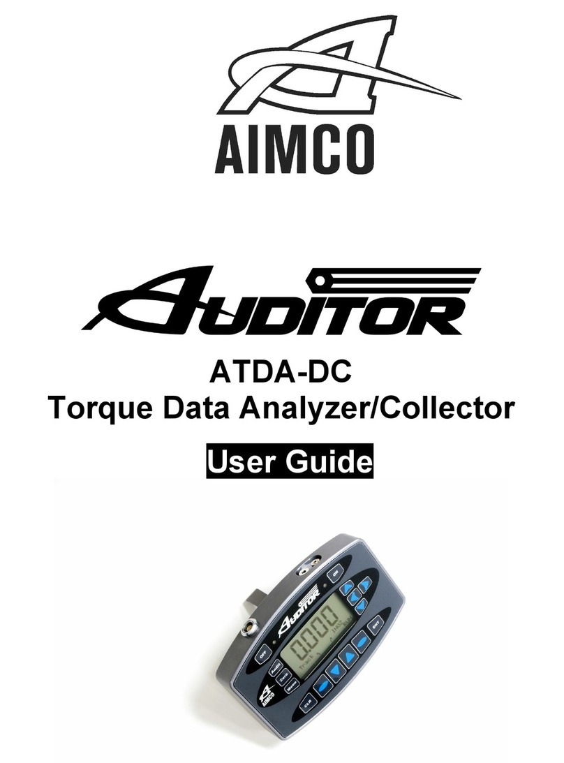
Aimco AUDITOR ATDA-8000 Series User manual

™
ATDA-8000 Series
Torque Data Analyzers
User Guide

2
CONTENTS
Unit Specifications................................................................................................... 2
Safety Requirements................................................................................................ 3
Screen and Button Diagrams
Main Screen..................................................................................................... 4
Settings Screen ................................................................................................ 5
Report Screen/ Results Screen........................................................................... 6
Basic Functions
Description of Settings Screen Functions ........................................................ 7-8
Operating Instructions
Basic Navigation............................................................................................... 9
Transducers
Transducers and Torque Measurement Cable.............................................. 11-12
Rundown Kits ................................................................................................. 12
Software
Auditor™ Tool Manager ............................................................................. 13-14
Auditor™ Data Manager ................................................................................. 15
Unit Specifications
Dimensions Width: 7”, Height: 5”, Depth: 1”
Weight 1 Lb
Power Requirements
Main Power 100-240VAC, 50-60hz from supplied charger
Operating Temperature Range 0oto 50oC
Data Communication Serial

3
SAFETY REQUIREMENTS
READ AND SAVE THESE INSTRUCTIONS
WARNING!
•Ensure that owner/operator has read
all Safety Requirements and User
Manuals prior to operating.
•To avoid electric shock, which may
result in personal injury and/or death,
electrical supply must be meet the
electrical requirements.
•Do not operate power tools in
explosive atmospheres, such as the
presence of flammable liquids, gases
or dust.
•To avoid electric shock, which may
result in personal injury and/or death,
electrical connections must be
properly grounded.
•To avoid electric shock, which may
result in personal injury and/or death,
electrical wiring between the device,
electrical supply and any peripheral
equipment must be routed in a secure
manner.
•Switch device to the “OFF” position
and disconnect from any power
supply prior to servicing. Lock Out/Tag
Out procedures should be followed.
•To avoid electric shock, which may
result in personal injury and/or death,
cords should be kept from heat, sharp
edges, or any other potentially
hazardous conditions.
•When operating a power tool
outdoors, use an extension cord
suitable for outdoor use.
•Keep out of reach of children.
DANGER!
•Contact with water, solvents, or other
liquid substances may result in
personal injury and/or death.
•Do not operate equipment under the
influence of drugs, alcohol or
circumstances in which you are not
fully alert.
•Use safety equipment. Always wear
eye protection.
•Ensure the switch is in the off-position
before plugging in.
•Remove any adjusting key or wrench
before turning the power tool on.
•Do not wear loose clothing or jewelry.
Keep hair, clothing and gloves away
from moving parts.
POWER TOOL USE AND CARE
•Do not force the power tool. Use the
correct power tool for your
application.
•Do not use the power tool if the power
switch does not turn it on and off.

4
SCREEN AND BUTTON DIAGRAM
Figure 1: Main Screen
1. Power Button
2. Data Display/Touch Screen
3 Mode / Units / Zero / Clear / Enter Buttons
4. Auto or Manual Buttons
5. Settings Button
6. Clear Test Run Button
7. Battery Indicator
8. Preset Tool Dropdown
Main Screen illustrates Target, Sample Reading, Mode, Engineering Unit, Full Scale
value of Transducer(s), Sample Auto Clear setting, Peak Blanking setting, Test Results
Auto Clear setting, Low Limit setting, Sign lock setting, High Limit setting, Frequency
Response setting, Number of Samples Captured and Battery Indicator
3
6
4
5
2
1
7
8

5
Figure 2: Settings Screen
1. Sample Auto Clear Setting 7. Mode Setting
2. Results Auto Clear Setting 8. Sign Lock
3. Samples Per Set 9. Frequency Setting
4. Threshold Setting 10. Peak Blank % Setting
5. 6 Sigma % Adjustment 11. Display Dimming Timer
6. Engineering Units Setting 12. Turn Off / Done / Restart Buttons
2
3
1
7
4
8
9
6
11
5
12
10

6
Figure 3: Results Screen
Results Screen illustrates Target Torque Value, Test PASS/FAIL, High/Low/Average,
Standard Deviation and Six Sigma percentage, Recorded samples and indicates Pass/Fail

7
BASIC FUNCTIONS
The ATDA-8000 has three screens: Main Screen, Results Screen, and Settings Screen.
Prior to using the instrument you should enter the SETTINGS SCREEN and program the
operation of the instrument.
Settings Screen/Menu
The following are your screen selection choices in the SETTINGS SCREEN:
Sample Auto Clear
Timer to either auto clear samples or auto
save samples. If left Off, the user will be
required to manually clear the readings
by pressing the Enter button on the Main
screen.
Results Auto Clear
Timer to either auto clear complete
sample set or auto save complete sample
set. If left Off, the user will be required to
manually clear the readings by pressing
the Clear Test Run button at the bottom
of the display in the Main screen.
Samples per set
Sets number of samples to be taken per
audit. Choose how many torque samples
per test by pressing the + or –buttons.
You may choose a maximum of 18.
Target
Sets Target/Nominal torque setting. After
entering the values press Save to store
them.
Low/High Limit
Sets limits either in percentage of target
or in specific numeric limits. Limits can
be enabled or left off. If they are OFF, turn
them on by pressing the OFF box and the
box will change to %. By pressing the
space to the left of the % symbol, the
number pad will pop up allowing user to

8
enter the +/- % that the tool will be tested
by. Press Save after entering values.
Units
Various engineering units, cycle from
INOZ, INLB, FTLB, Nm, CNm, gfcm, Kgfcm
and kgfm. The check box ensures that as
engineering units are changed, the Target
and Limits are also updated.
Mode Setting
By selecting the proper Operating Mode
the user can properly take torque
readings from a variety of manual and
powered tools.
•Peak
This mode will provide a display of
the maximum torque value achieved
by the tool during operation. This
mode is used for all continuous drive
tools and click-type torque wrenches.
•1st Peak
This mode will detect and display the
“first peak” achieved by click wrench-
es and cam-over screwdrivers.
•Pulse
This mode will display the maxi-
mum torque value achieved by
discontinuous drive tools such as
pulse tools and impacting tools.
•Track
This mode will display torque in
real-time as it is applied to the
connected transducer. Track mode
is used primarily for calibration of
the unit or identifying the condition
of the transducer. In Track Mode
with no torque on the transducer,
the display should show zero.
Sign Lock
Setting allows the user to select the
rotation direction in which a torque will be
captured. With Sign Lock ON, the initial
direction is set as the default direction; a
negative torque value indicates a reading
taken in the counter-clockwise direction
and a positive reading indicates a reading
taken in the clockwise direction. Any
readings taken in the non-selected
direction will be measured, but not
captured / displayed as a peak value.
With Sign Lock turned OFF, peak values in
both the clockwise and counter-clockwise
directions will be captured and displayed.
Since most torque rundowns are
conducted and readings are taken in the
clockwise direction, the user may find it
beneficial to turn this feature ON.
Frequency
Sets Frequency filter setting the analyzer
uses in monitoring the transducer signal.
For testing Continuous drive power tools,
500hz is recommended. For testing
Discontinuous drive tools 1000Hz is
recommended. Consult the specific tool
manufacturer for any other tool types.
Peak Blank
Determines the minimum threshold at
which a torque peak is captured. It is
entered as a percentage of the full scale
value of the transducer which is
connected to the ATDA-8000 and can be
displayed in values from 2 – 50% of
transducer full scale.
Dimming
Sets display timer
After choosing the settings of the unit select
the
Done
button and the unit will return to
the run mode with enabled settings. You
can also Restart or Turn Off the unit.

9
This unit is designed to operate semi
automatically. Once the settings are
complete, the user merely selects Done,
the system will cycle to the Main Screen
and the user can start taking readings.
The readings will clear (or be cleared by
the user) and be stored in a set. Once all
readings in the set are stored, the unit will
process the readings, providing the user
with High, Low, Average, Standard Devia-
tion and percentage of Six Sigma.
OPERATING INSTRUCTIONS
Using the Auditor™ Torque Data Analyzer (ATDA-8000)
1. Plug the 100 – 240 VAC Charger into DC Power Supply port.
2.
Plug the Charger into a 100 – 240 VAC power outlet using the appropriate plug end.
3. Prior to turning unit on, connect the transducer to an Auditor™ supplied cable
(
ICBL-8000DIG
) via any open USB port on the ATDA-8000.
4. To turn the ATDA 8000 on/off, press the “ON/OFF” button
(Figure 1).
5. The Charging Mode Indicator will illuminate as you are charging and show status.
6.
The ATDA must be used with the power supply / charger and transducer
connected. Due to the power demands of the transducers and peripherals the
system should always be used with AC power supply connected.
Basic Navigation and Use of the Keypad
The functions of the Auditor™ ATDA 8000 can be accessed by using the button
associated with the text on the display screen.
Main Screen/Menu

10
In the MAIN SCREEN you have four choices: Auto, Manual, Settings, and Clear Test Run.
By selecting Manual the system will be put into a quick check mode and will not have
the ability to save readings to the results screen.
By selecting the Auto button, the saving samples and Autoclear functions will be
activated. After a test run is completed the test data can be cleared manually or by using
the Results Auto Clear timer to automatically clear results.
Each of the following buttons can be used to execute a command:
•Select Auto or Manual mode
•Auto Mode allows user to
oClear readings
oZero the display/transducer
oEnter readings into Samples Captured screen
•Manual Mode allows user to
oSelect torque mode
oSelect engineering units
oZero display/transducer
oClear readings
•Settings enters the settings screen/menu

11
TRANSDUCERS
The ATDA 8000 can be used with a variety of Auditor™external transducers supplied
by AIMCO. The line of Auditor™ “Intelligent” and industry-standard transducers is
manufactured with the proper connector-style for ease of use with the ATDA 8000. For
assistance with this please contact your AIMCO Distributor or authorized AIMCO Sales
Representative at 1-800-852-1368.
Connecting a Transducer
Align the connector right side up
and firmly press the connector into the port. Tighten
the retaining bars to prevent cable from disengaging from transducer or instrument.
Power Cable End Transducer Cable End
Setting up the Transducer
The Auditor Torque Data Analyzer will recognize the transducer and report the full-scale
in the display.
Most transducers can be made to allow the Auditor Torque Data Analyzer to self-
recognize the transducer simply when a connection is made. For assistance with this,
please contact your AIMCO Distributor or authorized AIMCO Sales Representative at
1-800-852-1368
for a transducer upgrade quotation.
Torque Measurement Cable
Cable #ICBL-8000DIG connects from the ATDA-8000
series analyzer to AISI / AISF Transducers.

12
Auditor™ Stationary Transducers
Max Torque
Weight
W X H X D
Square
Drive
Transducer
Nm
in-lb/ft-lb
kg
lb
mm
in
in
AISI-200025
2.8
25
1.13
2.5
79 x 95 x 83
3.13 x 3.75 x 3.25
1/4
AISI-200100
11.3
100
1.13
2.5
79 x 95 x 83
3.13 x 3.75 x 3.25
1/4
AISI-200500
56.5
500
1.13
2.5
79 x 95 x 83
3.13 x 3.75 x 3.25
3/8
AISF-200100
135.6
1,200/100
2.25
5
100 x 65
4 x 3
1/2
AISF-200250
339
3,000/250
2.25
5
100 x 65
4 x 3
1/2
AISF-201000
1350
12,000/1,000
2.8
6
100 x 65
4 x 3
1
Rundown Kits
Auditor Transducers require the use of rundown kits. Please see details related to ARDIA
and ARDFA rundown fixtures.
Recommended Torque Range
Square
Model*
Description
In-Lb
Nm
Drive (IN)
ARDIA-10(HD)(HDE)(HDS)
Rundown Fixture
1.0 - 10
.13 - 1.13
1/4
ARDIA-25(HD)(HDE)(HDS)
Rundown Fixture
2.5 - 25
.28 - 2.8
1/4
ARDIA-100(HD)(HDE)(HDS)
Rundown Fixture
10.0 -100
1.3 - 11.3
1/4
ARDIA-250(HD)(HDE)(HDS)
Rundown Fixture
25.0 - 250
2.8 - 28.25
3/8
ARDIA-500(HD)(HDE)(HDS)
Rundown Fixture
50.0 - 500
5.6 - 56.5
3/8
ARDFA-100(HD)(HDE)(HDS)
Rundown Fixture
10 - 100
13.6 - 136
1/2
ARDFA-150(HD)(HDE)(HDS)
Rundown Fixture
15 - 150
20.4 - 204
1/2
ARDFA-250(HD)(HDE)(HDS)
Rundown Fixture
25 - 250
34.0 - 340
1/2
ARDFA-600(HD)(HDE)(HDS)
Rundown Fixture
60 - 600
81.6 - 816
3/4
ARDFA-100(HD)(HDE)(HDS)
Rundown Fixture
10 - 100
13.6 - 136
1/2
* Add “HD” to part numbers for wear resistant models. Add “HDS” to part numbers for fully encapsulated
wear resistant models.
* Add “HDE” to part numbers for partial encapsulated wear resistant models.
HDS Series
HD Series
HDE Series

13
AUDITOR TOOL MANAGER / DATA MANAGER SOFTWARE
Auditor™ Tool Manager Software
Tool Manager Software is included with the purchase of ATDA 8000 Series torque testers
and is imbedded into the unit. Create a database of tools and store test results with this
easy-to-use software integrator to/from tester to PC.
Tool Set up is easy with touchscreen access to type Tool Name, Serial #, Asset #,
Capacity, Model and Manufacturer information. Type of Tool and Capacity
(Engineering Units) have selections from drop down boxes when triangle is
touched. Once details are entered, touch ‘Save Tool’ button to save data.

14
To create Test Points, touch the ‘Create’ button to display the Create Test Point
Screen:
Touch screen to enter Target, Low/High Limit either in percentage of target or in
specific numeric limits as well as air pressure.
There are a wide range of additional, very specialized functions that the ATDA-
8000 series systems can accommodate. Hydraulic tools, measurement of pressure
observed through a pressure transducer and more can be audited with these
products.
Specific needs and training for these higher level functions/capabilities require
specialized hardware. Please consult your authorized AIMCO Auditor™
representative to receive further details.

15
Auditor™ Data Manager Software
Auditor Data Manager Software is included with the purchase ATDA-8000 series torque
analyzers. This software is imbedded into the unit. The View Data tab allows you to
look at the collected data. This data can be exported to Excel as a .csv file and
displayed by Excel charts. When selecting a test run - the average, range, sigma, Cp,
and CpK values are listed.
To export data:
•Click Audit Manager to open.
•Connect USB data stick to any open USB slot on the ATDA-8000 series analyzer.
•Look to bottom right corner of the ATDA-8000 screen. USB symbol should show to
the left of the battery condition symbol indicating the USB stick has successfully
mounted to the device.
•Select desired data to be exported by either
oSelecting specific audit
oSelecting date range
oSelecting all data
•Press Export Selected Data.
•Dialog box will display indicating successful transfer of data to the connected USB
stick
•USB stick may now be removed and taken to a PC for download and archiving.

16
AIMCO CORPORATE HEADQUARTERS AIMCO CORPORATION DE MEXICO SA DE CV
10000 SE Pine Street Ave. Cristobal Colon 14529
Portland, Oregon 97216 Chihuahua, Chihuahua. 31125
Phone: (503) 254–6600 Mexico
Toll Free: 1-800-852-1368 Phone: (01-614) 380-1010
LIT-MAN873 Rev.07/2020
Printed in USA ©2020 AIMCO
Table of contents
Other Aimco Measuring Instrument manuals