aion Obsidian User manual

OBSIDIAN METAL DRIVE 1
PROJECT NAME
OBSIDIAN
BASED ON
EFFECT TYPE
PROJECT SUMMARY
DOCUMENT VERSION
BOSS®MZ-2 Metalizer
The analog section of an obscure all-in-one digital metal pedal, featuring a JFET circuit very similar to
the BD-2 Blues Driver and OD-2 Overdrive.
Overdrive / distortion 1.0.0 (2023-09-08)
BUILD DIFFICULTY
Intermediate
Actual size is 2.3” x 2.42” (main board) and 1.78” x 0.86” (bypass board).

OBSIDIAN METAL DRIVE 2
TABLE OF CONTENTS
1Project Overview 8Drill Template
2Introduction & Usage 9Enclosure Layout
3-5 Parts List 10 Wiring Diagram
6Build Notes 11 Licensing
7Schematic 11 Document Revisions
INTRODUCTION
The Obsidian Metal Drive is based on the analog section of the BOSS®MZ-2 Digital Metalizer, first
released in 1987. Not to be confused with the Metal Zone (MT-2), the MZ-2 was an attempt at an all-
in-one metal pedal that includes onboard chorus and delay to replicate popular tones of the 1980s.
However, inside this digital pedal is an all-JFET analog drive circuit that bears a strong resemblance to
the BD-2 Blues Driver.
To play historian for a moment: the very first appearance of this JFET topology was in the OD-2
Overdrive, released in 1985, and the MZ-2 is only the second time it was utilized (at least tied with the
DS-2 Turbo Distortion, which also appeared in 1987). The BD-2 didn’t arrive until 1995, which means
the MZ-2 predated it by a full eight years.
Be aware that the analog circuit on its own is not very metal, especially compared to other BOSS circuits
such as the MT-2 or HM-2. The maximum gain is not terribly saturated and the tone control is just a
passive hi-cut with no ability to shape the midrange. It seems they were relying mostly on the digital
effects to sell the concept. But if you remove the pretense of metal, it’s a killer drive circuit on its own
and more than worth your time if you like the BD-2, OD-2 or OD-3.
We did make one circuit change in extracting the analog circuit from the MZ-2. The original unit uses an
op-amp at the output to mix together the analog and digital signals, which also acts as a buffer. Since the
rest of the analog circuit is all discrete, we opted to replace this op-amp stage with the transistor output
buffer from the BD-2 to keep the discrete topology intact. Having studied dozens of BOSS circuits, we’re
confident that this is how the engineers would have done it if there was no mixing requirement.
USAGE
The Obsidian has three knobs:
• Drive increases the gain of the second discrete op-amp stage, pushing it into clipping.
• Tone is a passive treble cut right before the output.
• Volume sets the overall output of the effect signal.

OBSIDIAN METAL DRIVE 3
PARTS LIST
This parts list is also available in a spreadsheet format which can be imported directly into Mouser for
easy parts ordering. Mouser doesn’t carry all the parts—notably potentiometers—so the second tab lists
all the non-Mouser parts as well as sources for each.
View parts list spreadsheet →
PART VALUE TYPE NOTES
R1 1M Metal film resistor, 1/4W
R2 4k7 Metal film resistor, 1/4W
R3 470k Metal film resistor, 1/4W
R4 2k2 Metal film resistor, 1/4W
R5 4k7 Metal film resistor, 1/4W
R6 4k7 Metal film resistor, 1/4W
R7 270k Metal film resistor, 1/4W
R8 2k2 Metal film resistor, 1/4W
R9 470k Metal film resistor, 1/4W
R10 33k Metal film resistor, 1/4W
R11 33k Metal film resistor, 1/4W
R12 4k7 Metal film resistor, 1/4W
R13 470k Metal film resistor, 1/4W
R14 4k7 Metal film resistor, 1/4W
R15 470k Metal film resistor, 1/4W
R16 4k7 Metal film resistor, 1/4W
R17 6k8 Metal film resistor, 1/4W
R18 2k2 Metal film resistor, 1/4W
R19 4k7 Metal film resistor, 1/4W
R20 10k Metal film resistor, 1/4W
R21 2k2 Metal film resistor, 1/4W
R22 47k Metal film resistor, 1/4W
R23 15k Metal film resistor, 1/4W
R24 470k Metal film resistor, 1/4W
R25 4k7 Metal film resistor, 1/4W
R26 100k Metal film resistor, 1/4W
R27 10k Metal film resistor, 1/4W
R28 2k2 Metal film resistor, 1/4W
R29 2k2 Metal film resistor, 1/4W
R30 4k7 Metal film resistor, 1/4W
R31 4k7 Metal film resistor, 1/4W
R32 4k7 Metal film resistor, 1/4W

OBSIDIAN METAL DRIVE 4
PARTS LIST, CONT.
PART VALUE TYPE NOTES
R33 4k7 Metal film resistor, 1/4W
R34 10k Metal film resistor, 1/4W
R35 1k Metal film resistor, 1/4W
R36 100k Metal film resistor, 1/4W
RPD 2M2 Metal film resistor, 1/4W
LEDR 10k Metal film resistor, 1/4W
C1 22n Film capacitor, 7.2 x 2.5mm
C2 3n9 Film capacitor, 7.2 x 2.5mm
C3 100n Film capacitor, 7.2 x 2.5mm
C4 100pF MLCC capacitor, NP0/C0G
C5 10n Film capacitor, 7.2 x 2.5mm
C6 22n Film capacitor, 7.2 x 2.5mm
C7 1n Film capacitor, 7.2 x 2.5mm
C8 18n Film capacitor, 7.2 x 2.5mm
C9 68n Film capacitor, 7.2 x 2.5mm
C10 4n7 Film capacitor, 7.2 x 2.5mm
C11 1uF Film capacitor, 7.2 x 3.5mm
C12 100pF MLCC capacitor, NP0/C0G
C13 10n Film capacitor, 7.2 x 2.5mm
C14 47n Film capacitor, 7.2 x 2.5mm
C15 10n Film capacitor, 7.2 x 2.5mm
C16 10n Film capacitor, 7.2 x 2.5mm
C17 1uF Film capacitor, 7.2 x 3.5mm
C18 1uF Film capacitor, 7.2 x 3.5mm
C19 47uF Electrolytic capacitor, 5mm Power supply filter capacitor.
C20 47uF Electrolytic capacitor, 5mm Power supply filter capacitor.
C21 47uF Electrolytic capacitor, 5mm Power supply filter capacitor.
C22 47uF Electrolytic capacitor, 5mm Power supply filter capacitor.
C23 47uF Electrolytic capacitor, 5mm Power supply filter capacitor.
C24 47uF Electrolytic capacitor, 5mm Power supply filter capacitor.
C25 100uF Electrolytic capacitor, 6.3mm Power supply filter capacitor.
C26 100n MLCC capacitor, X7R Power supply filter capacitor.
Z1 1N5232B Zener diode, 5.6V, DO-35
D1 1N5817 Schottky diode, DO-41
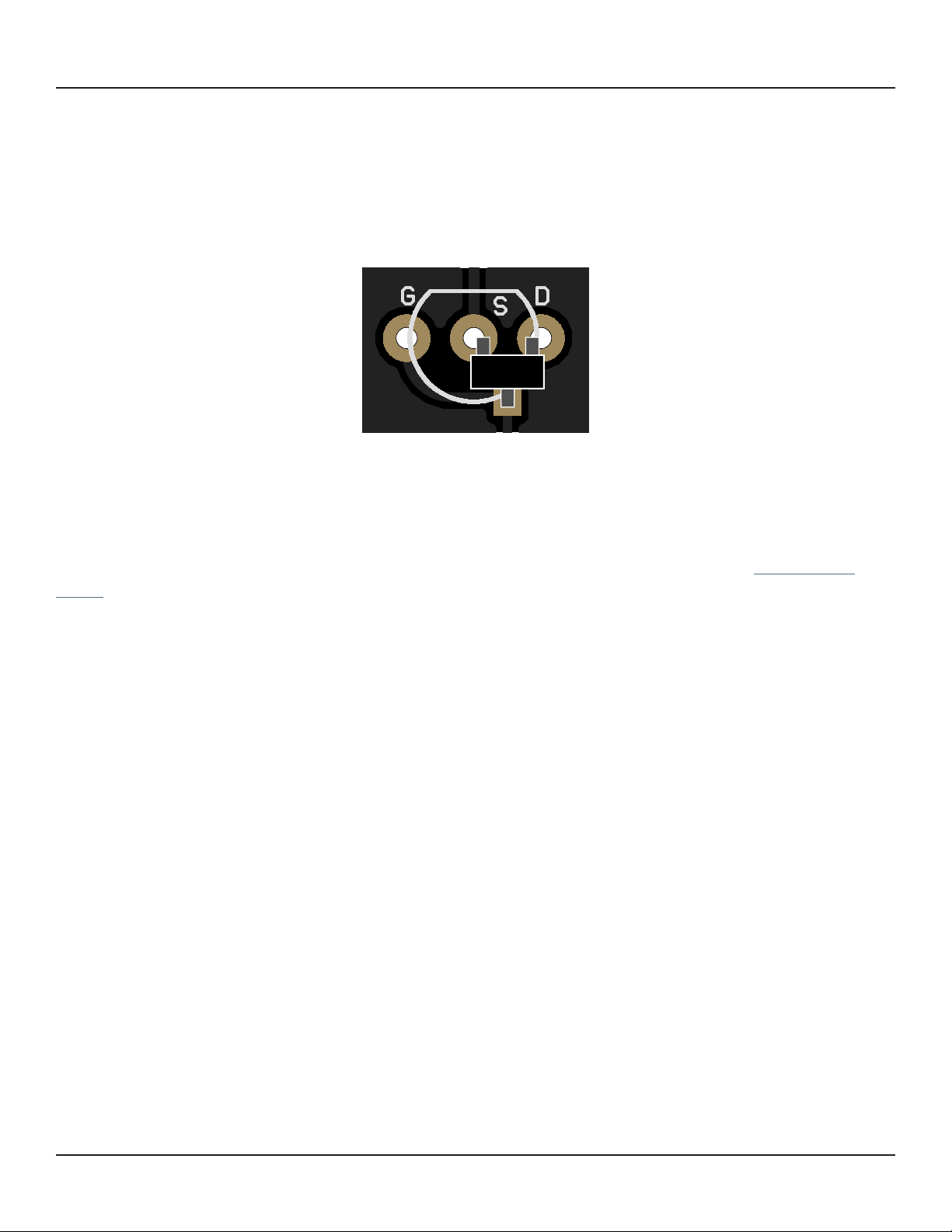
Q1 2SK209-GR JFET, N-channel, SOT-23 Original uses 2SK117-GR. 2SK209-GR is the SMD equivalent.
Q2 2SK209-GR JFET, N-channel, SOT-23 Original uses 2SK117-GR. 2SK209-GR is the SMD equivalent.
Q3 2SK209-GR JFET, N-channel, SOT-23 Original uses 2SK117-GR. 2SK209-GR is the SMD equivalent.

OBSIDIAN METAL DRIVE 5
PARTS LIST, CONT.
PART VALUE TYPE NOTES
Q4 2N3906 BJT transistor, PNP, TO-92 Substitute. Original uses 2SA970-GR.
Q5 2SK209-GR JFET, N-channel, SOT-23 Original uses 2SK117-GR. 2SK209-GR is the SMD equivalent.
Q6 2N5088 BJT transistor, NPN, TO-92 Substitute. Original uses 2SC2240-GR.
Q7 2SK209-GR JFET, N-channel, SOT-23 Original uses 2SK117-GR. 2SK209-GR is the SMD equivalent.
Q8 2SK209-GR JFET, N-channel, SOT-23 Original uses 2SK117-GR. 2SK209-GR is the SMD equivalent.
Q9 2N3906 BJT transistor, PNP, TO-92 Substitute. Original uses 2SA970-GR.
Q10 2N5088 BJT transistor, NPN, TO-92 Substitute. Original uses 2SC2240-GR.
Q11 2N5088 BJT transistor, NPN, TO-92
Q12 2N5088 BJT transistor, NPN, TO-92 Substitute. Original uses 2SC2458-GR.
Q13 2N5088 BJT transistor, NPN, TO-92 Substitute. Original uses 2SC2458-GR.
DRIVE 250kA 16mm right-angle PCB mount pot
TONE 10kB 16mm right-angle PCB mount pot
LEVEL 100kA 16mm right-angle PCB mount pot
LED 5mm LED, 5mm, red diffused
IN 1/4" mono 1/4" phone jack, closed frame Switchcraft 111X or equivalent.
OUT 1/4" mono 1/4" phone jack, closed frame Switchcraft 111X or equivalent.
DC 2.1mm DC jack, 2.1mm panel mount Mouser 163-4302-E or equivalent.
FSW 3PDT Stomp switch, 3PDT
ENC 125B Enclosure, die-cast aluminum Can also use a Hammond 1590N1.

OBSIDIAN METAL DRIVE 6
BUILD NOTES
Using SMD JFETs
The 2SK117-GR JFET is no longer available in through-hole format. This PCB uses a hybrid through-
hole/SMD outline for each JFET. An extra “G” (gate) pad is included to accommodate surface-mount
devices without the need for adapters.
SMD JFETs should be oriented as follows:
All surface-mount JFETs use the same pinout, so this configuration will fit any type that we’re aware of.
However, always check the datasheet if you’re uncertain—they’re difficult to desolder.
Using through-hole adapters
If you’re not confident in your ability to work with surface-mount parts, Aion FX offers 2SK209-GR
JFETs (the SMD version of 2SK117-GR and 2SK184-GR) that come pre-soldered to adapters for use
in through-hole designs. These are from the same manufacturer as the ones used in the original BOSS
pedals and will perform identically.

SCHEMATIC
OBSIDIAN METAL DRIVE 7
IN
+5V +2.5V+8.2V +4.1V+8.2V +5V
1N5817
100uF
100kA
250kA
10kB
+9V
100n
GND
22n
2SK117GR
VA
2k2
2N5088
47uF
GND
47uF
GND
VA
2k2
2N5088
47uF
GND
5.6V
GND
47uF
GND
1M
4k7
GND
3n9
VA
4k7
4k7
GND
47uF
VC VB VC
4k7
4k7
GND
47uF
VD
GND GND
470k
VC
VD
VC
2k2
4k7
GND
2SK117GR
2N3906
VC
4k7
100n
270k
100pF
GND
2k2
GND
2SK117GR
10n
4n7
470k
VB
33k 33k
22n
1n
GND
4k7
GND
18n
470k
VB
68n
4k7
470k
VB
2N5088
4k7
1uF
GND
6k8
VC
VC
4k7
GND
2SK117GR
2N3906
2k2
GND
VC
100pF
10k
47k
10n
15k
GND
47n
VD
2k2
470k
VB
2N5088
4k7
VA
GND
10n
10n
GND GND
1uF
100k
2N5088
10k
VB
VA
GND
1uF
VB
VA
VA
D1
C25
LEVEL
1
2
3
DRIVE
1
2
3
TONE
1
2
3
C26
C1
Q1
R28
Q12
C19
C20
R29
Q13
C21
Z1
C22
R1
R2
C2
R30
R31
C23
R32
R33
C24
R3
Q2
R4
R5
Q3
Q4
R6
C3
R7
C4
R8
Q5
C5
C10
R9
R10 R11
C6
C7
R12
C8
R13
C9 R14
R15
Q6
R16
C11 R17
Q7
R19
Q8
Q9
R21
C12
R20
R22
C13
R23
C14
R18
R24
Q10
R25
C15
C16
C17
R26
Q11
R27
C18
GND
GND
GND
10k
2M2
R34
RPD
100k
1k
OUT
R36
R35

OBSIDIAN METAL DRIVE 8
DRILL TEMPLATE
Cut out this drill template, fold the edges and tape it to the enclosure. Before drilling, it’s recommended
to first use a center punch for each of the holes to help guide the drill bit.
Ensure that this template is printed at 100% or “Actual Size”. You can double-check this by measuring
the scale on the printed page.
Top jack layout assumes the use of closed-frame jacks like the Switchcraft 111X. If you’d rather use
open-frame jacks, please refer to the Open-Frame Jack Drill Template for the top side.
LED hole drill size assumes the use of a 5mm LED bezel, available from several parts suppliers. Adjust
size accordingly if using something different, such as a 3mm bezel, a plastic bezel, or just a plain LED.
ø3/8” ø1/2”
0.385”
0.625” 0.625”
x: 0, y: -1.775
ø15/32”
x: -0.775, y: -1.775
ø5/16”
ø3/8”
125B
OUT
LEVEL DRIVE
TONE
FOOTSWITCHLED
DC IN
x: -0.65, y: +1.71 x: 0.65, y: +1.71
ø9/32” ø9/32”
x: 0, y: +0.66
ø9/32”
CENTER (0,0)
0 1 2
CM
0 1
INCH

OBSIDIAN METAL DRIVE 9
ENCLOSURE LAYOUT
Enclosure is shown without jacks. See next page for jack layout and wiring.
125B

OBSIDIAN METAL DRIVE 10
WIRING DIAGRAM
125B
IN +VGND NC NC OUT
PCB
IN
GND +V +V JACK GND JACK
OUTIN
GND GND PCB
OUT

OBSIDIAN METAL DRIVE 11
LICENSE & USAGE
No direct support is offered for these projects beyond the provided documentation. It’s assumed
that you have at least some experience building pedals before starting one of these. Replacements and
refunds cannotbe offered unless it can be shown that the circuit or documentation are in error.
All of these circuits have been tested in good faith in their base configurations. However, not all the
modifications or variations have necessarily been tested. These are offered only as suggestions based
on the experience and opinions of others.
Projects may be used for commercial endeavors in any quantity unless specifically noted. No
attribution is necessary, though a link back is always greatly appreciated. The only usage restrictions
are that (1) you cannot resell the PCB as part of a kit without prior arrangement, and (2) you cannot
“goop” the circuit, scratch off the screenprint, or otherwise obfuscate the circuit to disguise its source.
(In other words: you don’t have to go out of your way to advertise the fact that you use these PCBs, but
please don’t go out of your way to hide it. The guitar effects industry needs more transparency, not less!)
DOCUMENT REVISIONS
1.0.0 (2023-09-08)
Initial release.
Table of contents
Other aion Music Pedal manuals

aion
aion ANUBIS User manual

aion
aion Particle User manual

aion
aion CRESCENT AMP DISTORTION User manual

aion
aion TRITON MK. III User manual

aion
aion theseus User manual

aion
aion PHOBOS User manual

aion
aion FRACTAL PARAMETRIC OVERDRIVE User manual

aion
aion COMET User manual

aion
aion PROCYON User manual

aion
aion STRATUS User manual