FLARE FUZZ MACHINE 3
PARTS LIST
This parts list is also available in a spreadsheet format which can be imported directly into Mouser for
easy parts ordering. Mouser doesn’t carry all the parts (most notably potentiometers) so the second tab
lists all the non-Mouser parts as well as sources for each.
View parts list spreadsheet →
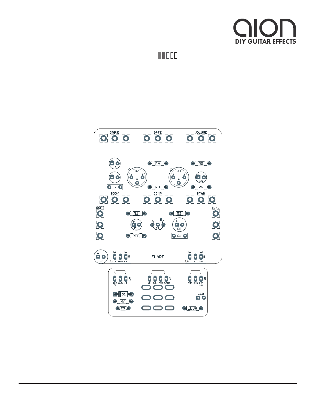
PART VALUE TYPE NOTES
R1 120k Metal film resistor, 1/4W
R2 10k Metal film resistor, 1/4W
R3 47k Metal film resistor, 1/4W
R4 470R Metal film resistor, 1/4W
R5 5k1 Metal film resistor, 1/4W
R6 220k Metal film resistor, 1/4W
R7 100R Metal film resistor, 1/4W Power supply filter resistor.
RPD 2M2 Metal film resistor, 1/4W Input pulldown resistor.
LEDR 4k7 Metal film resistor, 1/4W LED current-limiting resistor. Adjust value to change LED brightness.
C1 10uF Electrolytic capacitor, 5mm
C2 10n Film capacitor, 7.2 x 2.5mm
C3 10uF Electrolytic capacitor, 5mm
C4 10uF Electrolytic capacitor, 5mm
C5 10uF Electrolytic capacitor, 5mm
C6 18n Film capacitor, 7.2 x 2.5mm
C7 100uF Electrolytic capacitor, 6.3mm Power supply filter capacitor.
C8 100uF Electrolytic capacitor, 6.3mm Power supply filter capacitor.
C9 100n MLCC capacitor, X7R Power supply filter capacitor.
D1 1N5817 Schottky diode, DO-41
Q1 2N3904 BJT transistor, NPN, TO-92
Q2 Germanium Germanium transistor, PNP Recommended to buy a selected Fuzz Face set (Small Bear Electronics or
eBay). See build notes for more info.
Q3 Germanium Germanium transistor, PNP
DRIVE 10kB 16mm right-angle PCB mount pot
GATE 10kB 16mm right-angle PCB mount pot
VOL. 5kB 16mm right-angle PCB mount pot
BODY 100kB 16mm right-angle PCB mount pot
COMP 10kB 16mm right-angle PCB mount pot
STAB 10kB 16mm right-angle PCB mount pot
SOFT 100kB 16mm right-angle PCB mount pot
TONE 10kB 16mm right-angle PCB mount pot