Pg. 2
IS-IP4DVF Instr.
1015
Aiphone Corporation
www.aiphone.com
P: 800.692.0200
WIRING DIAGRAM:
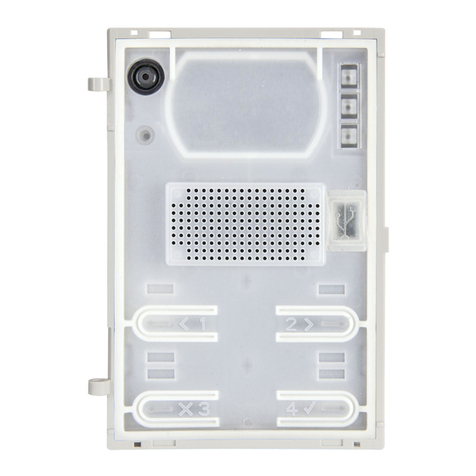
IS-IP4DVF
Back View
IS-IPMV
PROGRAMMING:
The IS-IP4DVF door station must be set as a host or client device like any other IS-IP door station or master
station. The unit must be registered to the IS-IP system before it can be programmed to call a master station
using the call buttons and RY-IP44 adaptor. Refer to Steps 5-7 in the IS Series IP Direct System Programming
Guide for information on setting client and host devices and registering IP stations.
SPECIFICATIONS:
Camera unit: CMOS camera
Scanning line: 525 lines
Min. illumination: 5 Lux at 1’6”
Terminations: RJ45 jack for audio/video
Screw terminals for door release and call buttons
Operating Temp: 14° ~ 140°F / -10° ~ 60°C
Wiring Distance: 328’ with CAT-5e/6 cable to switch
Dimensions: 12-3/8” H x 7” W
w/SBX-ISDVFP: 12-7/16” H x 7-1/16” W x 2-13/16” D (top), 1-13/16” D (bottom)
FCC WARNING:
This device complies with Part 15 of the FCC rules.
Operation is subject to the following two conditions:
(1) This device may not cause harmful interference.
(2) This device must accept any interference that may cause undesired operation.
• For proper regulatory compliance, the drain wire should be disconnected at the power
supply end of the cable.
• Changes or modications not expressly approved by the party responsible for
compliance could void the user’s authority to operate the equipment.
NO
COM
NC
To Strike
& Power
CAT-5e
CAT-5e
Note: Refer to the RY-IP44
Programming Manual for
information on programming
the adaptor.
IS-IPMV IS-IPMV
IS-IPMV
CAT-5e CAT-5e
CAT-5e
CAT-5e
I1
I2
G
G
I3
I4
RY-IP44
-
+
Power
~~~~~~
SA-1 SA-1 SA-1
SA-1 modules are included to protect the
RY-IP44 adaptor from surge. Locate the
SA-1 modules near the RY-IP44 adaptor
and connect the ground terminal on each
SA-1 to an earth ground.
