Aiphone RY-IP44 Owner's manual

RY-IP44
Programming Manual
For use with IX Series
This manual is for programming the RY-IP44 with the IX Series system only. Refer to the IX Series
Installation and Setting Manuals for complete installation/programming information.
For instructions featuring the RY-IP44 with the IS IP Series, visit www.aiphone.com/ISIP-RYIP44
For instructions featuring the RY-IP44 with the IPW-1A, visit www.aiphone.com/IPW1A-RYIP44
0319
Input/Output Network Adaptor
ATTENTION:
Note: IX Mobile should be included at the start of the creation of a new IX
Series system, rather than added after the system as been congured.
Refer to pages 9-11 of this manual for a walk-through of this process.

• RY-IP44
• 6 Screw Terminal Blocks
• MAC Address Label
Overview / Description
Package Contents
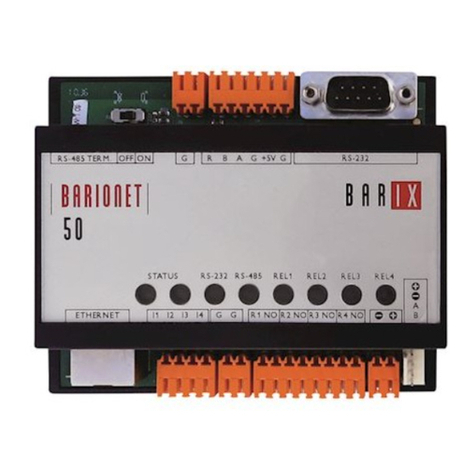
The RY-IP44 is a Barix “Barionet 50” with proprietary Aiphone rmware for use with IPW-1A, IS, or IX Series Stations.
The 4 individually programmable contact outputs can be used to trigger remote door release or external signaling,
triggering a contact closure while calling, communicating, or both calling and communicating.
The 4 individually programmable contact inputs can be used to trigger a call between two IX Series stations. For example,
use this function to trigger during an invalid card swipe, motion detector activation, or selective calling from multiple call
buttons.
The RY-IP44 is also used as the Mobile App Server for IX Mobile. An RY-IP44 is needed for every 8 instances of IX Mobile
and is used to alert the mobile device if it goes out of wireless network range.
When using the RY-IP44 only as a Mobile App Server for IX Mobile, begin on page 6 as SIF and CGI are not used in
this instance. Refer to pages 8-14 for steps on creating a system with IX Mobile and conguring IX Mobile.
Note that the RY-IP44 is not a PoE device, and requires a separate 9-30v DC power supply. It is recommended to use the
Aiphone PS-1208UL.
• General understanding of IX Series programming
• 9-30V DC power supply (sold separately)
• Unique IP address for each adaptor
Installation Requirements
Updating Firmware on RY-IP44
2 | RY-IP44 with IX Programming Manual
Ensure that the RY-IP44 has the current rmware loaded. The current version is 2.2 can be downloaded from the
Aiphone website (www.aiphone.com/home)
Using a web browser, access the RY-IP44 using its default IP address of 192.168.1.45. The landing page will be the
Device Status screen.
Click CONFIGURATION
Step 1
Click UPDATE
Step 2
Note the loaded Aiphone Firmware. If it is V2.2, it is up to
date. If not, click Please click here to continue.
Step 3
Click Choose File and
navigate to and select
the current rmware.
Step 4
Once selected, click
Upload.
Step 5
Afer the station has successfully loaded the new rmware,
click Update, then reboot the adaptor.
Step 6

Expand Function Settings and
select SIF from menu on left.
Step 1 Use the Number drop-down under Select
Station to Edit and choose the door station.
Click Select and ensure that the door station
is shown in upper left of the screen.
Step 2
Enabling CGI & SIF on IX Series 2 Stations
Select the Enable radio buttons
for CGI and SIF Functionality
Step 3
Under SIF Settings, enter a Program Type, the IP Address, and Destination Port
for the RY-IP44 relay. Use a separate line for each RY-IP44 being used.
Step 4
Program Type: Any binary number between 0100 and 1111
IPv4: IPv4 Address assigned to RY-IP44
Destination Port: Port number assigned to RY-IP44 (10000 is default)
SSL: Select if SSL will be Enabled or Disabled (Set to disable)
Connection: Select if connection is Socket or HTTP (Set to socket)
Choose the Transmission Trigger Events that this
station will need to send to the RY-IP44. The Begin
Outgoing Call, Begin Communication (Source),
End Communication, and Change contact events
are the most common and will cover most aspects of
RY-IP44 integration.
Step 5
Click Update to save changes.
Step 6
Repeat Steps 2-6 for each IX 2 station
interacting with the RY-IP44 relay.
3 | RY-IP44 with IX Programming Manual
The steps above are specific to IX Series 2 stations. IX Series 1 stations will be configured differently. Please follow the steps on
pages 4 and 5 for any IX Series 1 stations (IX-DA, IX-BA, IX-MV).
If the system does not contain any IX Series 1 stations, go to the bottom of page 5 to upload settings to stations.
IX Series stations use SIF events to interact with and trigger the contact outputs of the RY-IP44, and CGI is used when the
RY-IP44 interacts with a station using the contact inputs. Enabling both SIF and CGI for each station and then configuring their
settings are required. Once these parameters are set, the event triggers are configured. Each of these steps are shown below
using the IX Support Tool software.
Important:
The intercom system should be fully programmed and operational prior to programming for the RY-IP44 adaptor integration.
Open IX Support Tool and select a system program file by clicking File > Selecting Existing System.
Change IX Support Tool to .

Creating the SIF.ini File (For IX Series 1 Only)
Creating a simple line of code, in the form of a .ini file, is required to allow an IX Series 1 (IX-DA, IX-BA, IX-MV) device to
communicate to the RY-IP44. The example below is shown using a common text editor (i.e. Notepad), and saving it with an .ini
extension.
Program Type: A binary number between 0100 and 1111.
RY-IP44 IP Address:
IP address assigned to the RY-IP44 (Must be unique for each RY-IP44).
Destination Port:
Port number assigned on the RY-IP44. The default port is 10000. This can be
set in the range from 1 to 65535 (Must be unique for each RY-IP44).
SSL Y/N :
This device does not use SSL. Input 0 for no.
Example Text File: 0100,192.168.1.45,10000,0
Save the SIF le with a .ini extension (.ini must be typed manually) to a location on the PC being used for programming the IX
Series 1 stations. This le must be uploaded to each device associated with the RY-IP44 using the instructions that follow.
Program
Type
RY-IP44
IP Address
Destination
Port
SSL
Y/N
Important:
The intercom system should be fully programmed and operational prior to programming the RY-IP44 adaptor.
4 | RY-IP44 with IX Programming Manual
Expand Function Settings and
select SIF from menu on left.
Step 1
Use the Number drop-down under Select
Station to Edit and choose the door station.
Click Select and ensure that the door station
is shown in upper left of the screen.
Step 2
Open IX Support Tool and select a system program file by clicking File > Selecting Existing System.
Change IX Support Tool to .
Enabling CGI & SIF on IX Series 1 Stations

Upload Settings to Station
Click File, Upload
Settings to Station
Step 1
Check the box beside each station that was modied, then click
Settings under “Select le type to be uploaded”
Step 2
You will be asked if you want to
continue. Click OK.
Conrm Success/Failed in the Status
Column.
Step 3
5 | RY-IP44 with IX Programming Manual
Select the Enable radio buttons
for CGI and SIF Functionality
Step 3
Enabling CGI & SIF on IX Series 1 Stations (continued)
Click Browse and navigate to
where the SIF.ini le is saved
and select it. Click Upload to
send it to the station.
Step 4
Click Update to save changes.
Step 5
Repeat Steps 2-5 for each IX Series 1 station
interacting with the RY-IP44 relay.

Conguring the RY-IP44
Relay status and control.
Click on each LED to verify
relay function.
Digital input status
Conguration button
Using a web browser, access the RY-IP44 using its default IP address of 192.168.1.45. The landing page will be the
Device Status screen.
Click the CONFIGURATION button to open the Device Conguration screen. This is where a unique IP Address,
Netmask, and Gateway can be assigned to the adaptor.
The Aiphone system type that the adaptor is being integrated with will need to be selected. Click the AIPHONE tab. Use
the drop down by System Type to select IX.
System Type: Select IX
SIF Socket Local Port: If left at 0, the default
value of 10000 will be used. Ensure that the
port entered here is the same port used when
conguring the SIF settings on Page 3.
Username & Password: Enter system’s
username and password. If left blank, the default
value of “admin” is used.
IX Mobile App Server Port: Enter the App Server
port congured in IX Mobile. If left blank, the
default value of 5061 is used.
Enter IP Address that was entered in
the SIF Settings.
6 | RY-IP44 with IX Programming Manual
AIPHONE: Select the Aiphone system
type the relay is to be used with.

From the DEVICE CONFIGURATION screen, click APPLICATION SETUP.
APPLICATION SETUP button
Relay Action options:
• Door Release - Normally-Open
• Door Release - Normally-Closed
• Active while Calling from Source
• Active while Communicating
• Active during Calling and Communicating
When the relay action is set for one of the “Door Release” options, the relay on the RY-IP44 will trigger when the
associated station’s door release contact is triggered.
When the relay action is set for any of the “Active While” options, the relay will trigger when the associated station calls
or communicates at any priority level.
Relay will trigger when the associated station’s door release contact is triggered.
Relay will trigger when the associated station calls or communicates.
}
}
IX Series: Relay Output Programming
7 | RY-IP44 with IX Programming Manual
When the relay action is set for Door Release, the station number to be entered will always be that of the door station. The
door station is the device that will be sending the SIF command/event to the RY-IP44 adaptor that its relay status has changed.
• Enter the Station number of the station sending the SIF event to the RY-IP44 to be associated with this output.
• Select the relay condition from the Relay Action drop down menu.
• Click on Apply Settings, then click Reboot to restart the adaptor with the saved changes.
When the entered station is active, the associated relay will trigger based on the Relay Action settings.

IX Series: Input Programming
Note: The RY-IP44 inputs can have dierent calling rules than the default calling rule set for a station during the IX Series programming.
• Select the call-in priority level for each input using the Priority drop down menu.
• Enter the target IP address of the station to place the call.
• Click Apply Settings to save the changes. Do not reboot the adaptor at this time.
• Click APPLICATION SETUP to return to the Application Conguration Screen.
• Click on Destinations next to the input being congured. In the new window, enter the station number of the master
station(s) to be called when the input is triggered.
• When the target IP address is a door station, a maximum of 20 master stations can be entered.
• When the target IP address is a master station, a maximum of 20 master stations or 1 group can be entered. A group
can consist of up to 50 master stations and must be created using the IX Support Tool.
• Check the Enable box beside each station entered.
Click on Apply Settings, then click Reboot to restart the adaptor with the changes.
Station Placing Call
Conguring the IX Mobile Server
Set the RY-IP44 for use with the IX Series (refer to page 4).
Enter the Static IP address for each of the mobile devices in the IX Mobile Server Functionality table.
If DHCP is required, static reservations will be required for each mobile device.
Click on Apply Settings, then click Reboot to restart the adaptor with the changes.
Refer to pages 7-11 for steps on adding a mobile device to the IX system using the IX
Support Tool and for setting up the mobile device.
IX Mobile
IX Mobile is an app for iOS (v8.0 – v12.1) and Android (v4.1+) turning a mobile device into an IX Series sub master
station, allowing for 2-way audio communication, video, and door release. 4 programmable shortcut buttons can be
congured to initiate a call to specic stations, groups, or page.
The following steps assist in the conguration of an IX Series system with IX Mobile and the conguration of IX Mobile
on a mobile device.
Requirements: A system must contain at least one IX-MV or MV-7-* when using IX Mobile and one RY-IP44 for every 8
instances of IX Mobile. IX Mobile also requires a constant connection to the network the IX Series system is deployed
to, utilizing either a Wi-Fi connection or a VPN.
8 | RY-IP44 with IX Programming Manual

Creating a System Including a Mobile Device
Connect all IX Series stations and the programming PC to a PoE switch. Open IX Support Tool on the programming PC.
9 | RY-IP44 with IX Programming Manual
From the Menu bar, click File, then
Create New System.
Step 1
Enter a System Name and enter the
quantities of each type of station to be
programmed in the appropriate boxes.
(Note: every Mobile device will be considered
an IX-MV)
Click Next when done.
Step 2
The System Conguration page will
open and the Station Settings List
will be populated based on what was
entered in step 2.
Click on Station Details.
Step 3
The Station Details page will open.
On this page, a unique number and
name can be assigned to each station
in the system. The IP Address assigned
to each station can also be changed
from what Support Tool automatically
assigned.
When done making changes, click OK.
Step 4

10 | RY-IP44 with IX Programming Manual
Creating a System Including a Mobile Device (continued)
The stations can be associated to the settings automatically or manually. Automatic Association will pair like
type stations from the top Station Settings List to the Station List below.
This guide will show the Manual Association process.
Note: Mobile devices can not be associated during this process.
Select the setting le to be associated.
Step 5.1
Select the scanned station to be
associated to the setting le.
Step 5.2
Click Apply to associate the selected
station with the selected le.
Repeat process until all stations are
associated ensuring that the mobile
device is NOT selected from the upper
Station Settings List.
Step 5.3
Scroll Down Scroll Down
Conrm that each IX station has been
successfully associated in the Status
column.
Step 5.4
If all stations show Success, click
Next.
Step 5.5
Note: The IX Mobile station should never
appear in the Associated Stations List.
The process for loading the setting le
to the mobile device will be covered later
in this guide.
A warning will appear letting you know
that some stations have not been
associated. This is because Mobile
can not be associated this way. Click
OK to continue.
Step 5.6

11 | RY-IP44 with IX Programming Manual
Creating a System Including a Mobile Device (continued)
After each station has been associated with its individual station information, the setting le containing
the rest of the system’s information will need to be uploaded to each station. To upload the setting le, the
programming PC will need to be in the same subnet as the associated stations. The PC’s current IP address is
displayed in the bottom left-hand side of this window.
Note: If the setting le is not uploaded, most functions and features will be unavailable to the stations.
Choose All from the Select Station
by Type drop down, then click Select.
Step 6.1
Once station Status shows
Available (may take a few
minutes), click Start Upload.
Step 6.2
After successful upload,
click Next.
Step 6.3
The progress of each station will
be displayed in the Status column.
Unavailable stations may still be
rebooting from the association process.
If a station has rebooted and is still
unavailable, ensure the programming
PC is in the same subnet as the station.
Note:
The Export Settings window will open. Click on Export and choose
a destination on your PC to export the system settings to. Click OK to
export and save the settings.
Step 7.1
Click Finish.
Step 7.2
The Setting File must be exported in order to obtain the conguration le required to set up the IX Mobile devices.
Click File > IX Support Tool Export System Conguration then follow the steps above.
After clicking Next in Step 6.3, you will be prompted to export settings. The settings must be exported prior to
setting up the mobile devices with IX Mobile.

1
2
3
4
5
• Navigate to the location that you exported the system settings to. Open the le and click on the Setting folder.
Locate the conguration le with the same number that was assigned to the mobile station in IX Support Tool.
Copy the conguration le to a location on the programming PC that can easily be transferred to the mobile device.
• The folder containing the conguration le may be hidden. To show hidden folders, open Windows Explorer and
click 1
Organize (Windows 7), or File (Windows 10)
. Click 2
Folder and search options (Windows 7), or
Options (Windows 10)
. Select the 3
View
tab and select the radio button beside 4
Show hidden les, folders,
and drives,
then click 5
OK
.
The exported settings le will have a conguration le for each station in the system. The conguration le for the
mobile station will need to be uploaded to the mobile device using the steps on pages 11 and 12.
Conguration File
Windows 7 Windows 10
IX Mobile Station Details
Conguration File Example:
12 | RY-IP44 with IX Programming Manual
1
2
Note Station Information here to refer to later
Number
Name IP Address
...
...
...
...
...
...
...
...
It is recommended that the station number, station name, and IP address that was assigned to each instance
of IX Mobile in the Support Tool be written down for future reference when setting up the mobile devices.
Please use the table below to document this information.

Download IX Mobile from the App StoreSM
Connect to the WiFi network associated with the IX Series
system installation. Once connected, tap on the connected network.
Tap
Static and enter the IP Address that was assigned when
conguring the app with the IX Support Tool
.
Connect the mobile device to the PC that has iTunes installed.
Open iTunes and click File Sharing. Select IX Mobile. Click
Add File and navigate to where the conguration le is saved.
Select the le and click Open.
1
2
3
4
5
1
2
3
4
5
Launch the application on the mobile device.
Tap the Menu icon.
6 6
7
Tap
Setup
.
Enter the Admin ID and Password and tap
OK
.
Default ID: admin
Default Password: admin
7
8
8
A pop-up will appear stating “New conguration applied.”
9To unlock the app, call the mobile device from a master station
in the system.
App Store is a service mark of Apple Inc.
Tap Import from File.
Select the conguration le that was transferred to this device
in Step 3. Tap OK.
Tap
App Server
. Enter the IP Address and Port Number for
the App Server (RY-IP44). Refer to page 11 for information on
setting up the App Server.
Apple, the Apple logo, iPhone, iPad, iPod touch, and iTunes are trademarks of Apple Inc., registered in the U.S. and other countries. The App Store
is a service mark of Apple Inc.
App Installation and Setup for Apple
13 | RY-IP44 with IX Programming Manual
192.168.1.15
cong-102-20181114112622.txt

Download IX Mobile using Google PlayTM
Connect to the WiFi network associated with the IX Series
system installation. Once connected, tap and hold on the
connected network.
A pop-up will appear. Tap
Modify network cong
.
Check the box beside
Show advanced options
.
Under
IP settings
, select
Static
and enter the IP Address that
was assigned when conguring the app with the IX Support
Tool. Once entered, tap Save.
Connect the mobile device to the PC used for programming the
system. Using the PC, navigate to the mobile device and locate
the ixapp_settings folder. Paste/transfer the conguration le
saved from the IX Support Tool to this folder.
1
2
3
4
5
1
2
3
4
5
Launch the application on the mobile device.
Tap the Menu icon, then tap
Settings
.
66
7
Tap
Setup
.
Enter the Admin ID and Password and tap
OK
.
Default ID: admin
Default Password: admin
7
Tap
Import from File
.
Select the conguration le that was transferred to this device
in Step 5. Tap
OK
.
9 9
A pop-up will appear stating “Service started with a new cong.”
11 To unlock the app, call the mobile device from a master station
in the system.
10
10
Tap
App Server
. Enter the IP Address and Port Number for
the App Server (RY-IP44). Refer to page11 for information on
setting up the App Server.
88
Android, Google Play, and the Google Play logo are trademarks of Google Inc.
App Installation and Setup for Android
Note: On Android devices running version 7.0 or newer, battery optimization must
be disabled for the IX Mobile app to maintain network connection.
14 | RY-IP44 with IX Programming Manual
192.168.1.15
cong-102-20181114112622.txt

RY-IP44 Wiring
15 | RY-IP44 with IX Programming Manual
Aiphone Corporation
www.aiphone.com
800-692-0200
RY-IP44 Dimensions
4-1/8”
3-5/16”
Mounting:
The RY-IP44 adaptor mounts to an Aiphone
W-DIN11 mounting rail (sold separately).
Depth:
1-1/4”
Door release: External signaling:
Inputs:
Connect a normally open (N/O) contact across any
input and ground.
Power:
Use a 9-30V DC (300mA @ 12VDC) power supply to
power the RY-IP44 adaptor.
Use the Aiphone
PS-1208UL power supply (sold separately).
R1
NO
R3
NO
PT
Door
Strike Bell
= Power Transformer (use proper power for the strike, mag lock, or external signaling device being used).
PS-1208UL
PT
PT
R2
NO
R4
NO
R1
NO
R3
NO
R2
NO
R4
NO
+
-
+
-
I1
I2
G
G
I3
I4
Input 1
Input 2
Input 3
Input 4
Ground {
{
{
{
{
Relay 1
Relay 2
Relay 3
Relay 4
{
{
{
{
Relay 1
Relay 2
Relay 3
Relay 4
{
Power
Relay contact rating: 30V DC, 0.5A.
FCC WARNING:
This device complies with Part 15 of the FCC rules.
Operation is subject to the following two conditions:
(1) This device may not cause harmful interference.
(2) This device must accept any interference that may cause undesired operation.
• For proper regulatory compliance, the drain wire should be disconnected at the power supply end of the cable.
• Changes or modications not expressly approved by the party responsible for compliance could void the user’s
authority to operate the equipment.
0319
Other manuals for RY-IP44
3
Table of contents
Other Aiphone Receiver manuals

Aiphone
Aiphone DAK-2S User manual

Aiphone
Aiphone MYW-MD User manual

Aiphone
Aiphone TD-H Series User manual
Aiphone
Aiphone NB-U User manual
Aiphone
Aiphone RY-3DL User manual

Aiphone
Aiphone SKK-620C User manual

Aiphone
Aiphone IXW-MA User manual

Aiphone
Aiphone MC-A/A User manual

Aiphone
Aiphone MYW-BA User manual

Aiphone
Aiphone AXW-AVR User manual
Aiphone
Aiphone MYW-BA User manual
Aiphone
Aiphone MYW-BA User manual
Aiphone
Aiphone KCS-IFA User manual
Aiphone
Aiphone LEF Series User manual

Aiphone
Aiphone IS-IPRY Owner's manual

Aiphone
Aiphone KCW-D/B User manual

Aiphone
Aiphone MYW-BA-M User manual

Aiphone
Aiphone PS-12F User manual
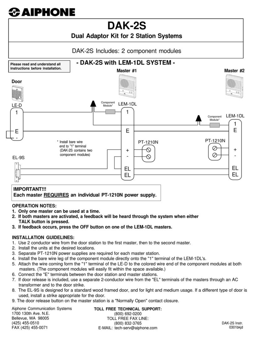
Aiphone
Aiphone MYW-BA User manual