MN-754
Air Lift PerformanceAir Lift Performance
•Using a butt connector attach the RED compressor wire to the PINK harness wire.
•Using a butt connector attach the BLACK compressor wire to the BLACK harness wire.
• Carefully apply heat (preferably with a heat gun) to seal these connections.
3. Battery / ignition connections (see g. 15)
• Identify the power, ground, + ignition leg of the harness.
• Ground: 10AWG black wire; Power: 10AWG red wire; Ignition: 18AWG pink wire.
•Route power and ground leg of the harness free from any heat source to the battery.
• Using a butt connector attach the red wire to a fuse holder.
•Attach an 3/8” eyelet to the other end of the fuse holder and attach to the positive
battery (+) terminal.
•Attach an 3/8” eyelet to the black wire and attach to the battery ground.
•Route the 18AWG pink wire to a key switched IGNITION source that remains on
during cranking. Examples include: ECU, fuel pump.
Do not select an accessory source. If the AutoPilot V2 display shuts off while starting the
vehicle, this is not a true ignition source.
• Using a butt connector attach the pink ignition wire to a fuse holder.
• Select ignition source and attach the fused ignition wire.
• Use fuse adaptors as necessary.
4. Display
• Route the display cable as desired to the preferred operating location.
•Attach the display cable to the main harness cable (small white 3 cavity connector).
5. Reconnect the battery.
INSTALL AIR LINES
Use a standard hose cutter (Air Lift part number 10530) or razorblade. Cut all hose ends
square and as smoothly as possible.
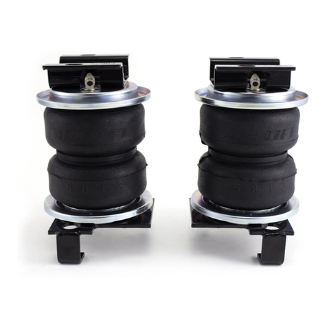
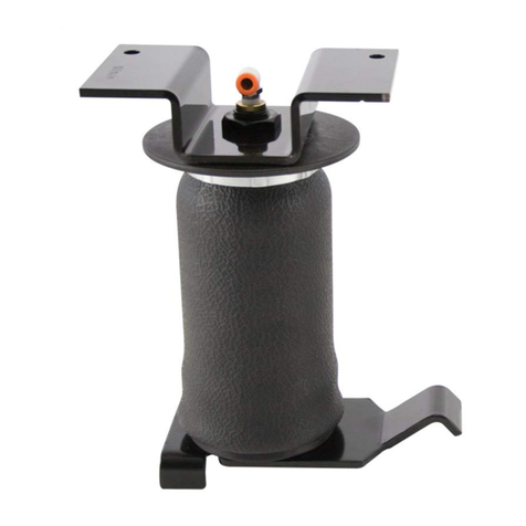
1. Route and attach the air lines to the air springs.
• Route air lines free from abrasive edges and heat sources.
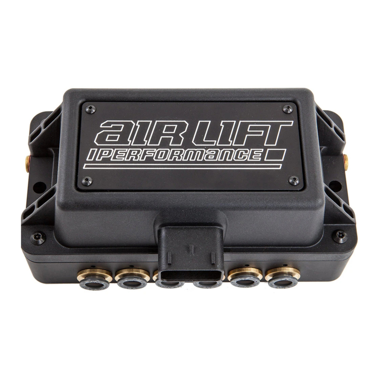
2. Attach manifold port FL to the front, drivers side left spring.
3. Attach manifold port FR to the front, passengers side right spring.
4. Attach manifold port RL to the rear, drivers side left spring.
5. Attach manifold port RR to the rear, passengers side right spring.
6. Attach manifold port T to the PTC tting previously installed on the lter.
7. Manifold port Eis the exhaust port.
• Port E can be left open, or routed to a preferred exhaust location.
Air lines should be pushed in rmly, with a slight back and forth rotational twist – check the
connection by pulling on each line to verify a robust connection.
Release the air line from the tting by releasing air, pushing on the line, depressing the ring
towards the tting, and then pulling the hose out of the tting.
NPT ASSEMBLY INSTRUCTIONS
1. Inspect the port and tting ensuring both are free of contaminants and excessive burrs
and nicks.
2. Apply a stripe of liquid pipe sealant around the male threads leaving the rst two threads
uncovered.
3. Screw nger tight into the port.
4. Wrench tighten the tting to the correct turns past nger tight position (see table 1
located on page 6).
NEVER BACK OFF AN INSTALLED PIPE FITTING TO ACHIEVE PROPER ALIGNMENT.
LOOSENING INSTALLED PIPE FITTINGS WILL CORRUPT THE SEAL AND CONTRIBUTE
TO LEAKAGE AND FAILURE.
NOTE
NOTE
NOTE
CAUTION


