3
Technical Support
1-800-248-0892
III. Installing the Assembly
1. Set the assembly on the leaf spring and insert two 1/2" carriage
bolts (L) through the bottom holes in the upper bracket and then
through the frame. Install a flat washer (M) and nylon lock nut
(N) to each bolt. Refer to Figure 1. Leave loose for
adjustment.
2. Insert two 3/8" frame bolts (I) through the top holes in the
upper bracket and frame. Secure using two flat washers (H)
and two nylon lock nuts (K) to the inside of the frame (Fig. 1).
3. Tighten all upper bracket mounting hardware at this time.
4. Insert four 3/8" bolts (J) and four flat washers (H) into the
holes on the lower bracket (Figure 1).
5. Slide two clamp bars (O) onto the bolts hanging from the lower
bracket and attach using four flat washers (H) and four nylon
lock nuts (N). Refer to Figure 1.
6. The lower bracket is slotted for in and out alignment of the air
spring. Align the air spring so that it is parallel and perpendicular
to the top and bottom. When aligned, tighten all mounting
hardware, including the lower air spring hardware to the specified
torque value found on page 5.
IV.Installing the Air Lines
1. Choose a convenient location for mounting the inflation valves
and drill a 5/16" hole to install the inflation valves. Popular
locations for the inflation valve are: the wheel well flanges, license
plate recess in bumper, under the gas cap access door, or
through license plate itself. NOTE: What ever the chosen
location is, make sure there is enough clearance around the
inflation valves for an air chuck.
2. Cut the air line assembly (AA) in two equal lengths. CAUTION: When cutting or trimming the air line, use a hose
cutter (Air Lift P/N 10530), a razor blade or a sharp knife. A clean, square cut will ensure against leaks. Do not use
wire cutters or scissors to cut the air line. These tools may flatten or crimp the air line, causing it to leak around the
O-
ring seal inside the elbow fitting.
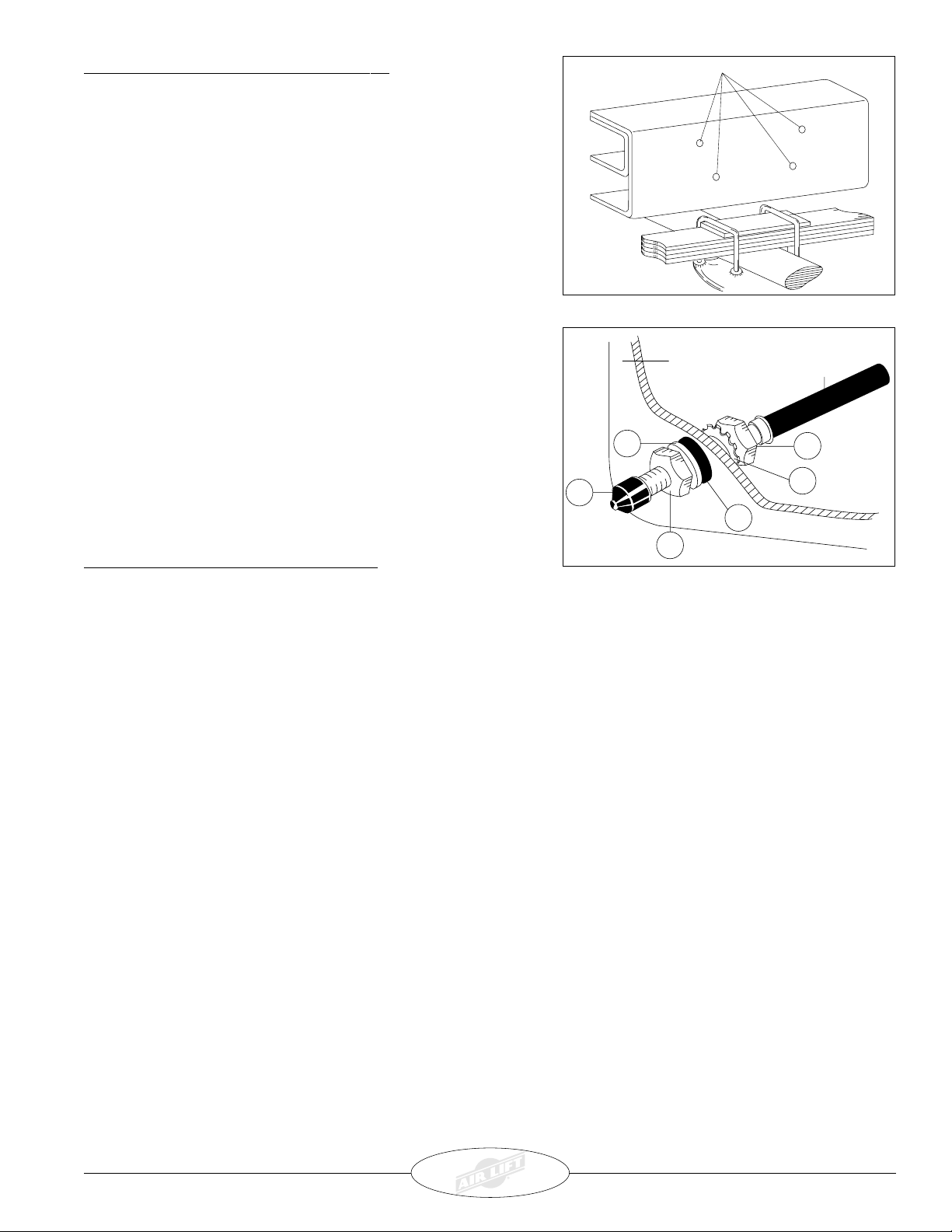
3. Place a 5/16" nut (GG) and a star washer (FF) on the air valve. Leave enough of the inflation valve in front of the
nut to extend through the hole and have room for the rubber washer (EE), flat washer (DD), and 5/16" nut (GG) and
cap (CC). There should be enough valve exposed after installation - approximately 1/2" (13mm) - to easily
apply a pressure gauge or an air chuck (Figure 5).
4. Push the inflation valve through the hole and use the rubber washer (EE), flat washer (DD), and another 5/16"
nut (GG) to secure it in place. Tighten the nuts to secure the assembly in place (Figure 5).
5. Route the air line along the frame to the air fitting on the air spring. Keep at least 6" (150mm) of clearance
between the air line and heat sources, such as the exhaust pipes, muffler, or catalytic converter. Avoid sharp
bends and edges. Use the plastic zip ties (BB) to secure the air line to fixed, non-moving points along the chassis.
Be sure that the zip ties are tight, but do not pinch the air line. Leave at least 2" (50mm) of slack to allow for any
movement that might pull on the air line.
6. Cut off air line leaving approximately 12" (300mm) of extra air line. A clean square cut will ensure against leaks.
Insert the air line into the air fitting. This is a push to connect fitting. Simply push the air line into the 90 degree
swivel fitting until it bottoms out (9/16" of air line should be in the fitting).
Figure 4
Air Line to
Bellows
FF
Vehicle body
or bumper
GG
GG
EE
DD
CC
Figure 5