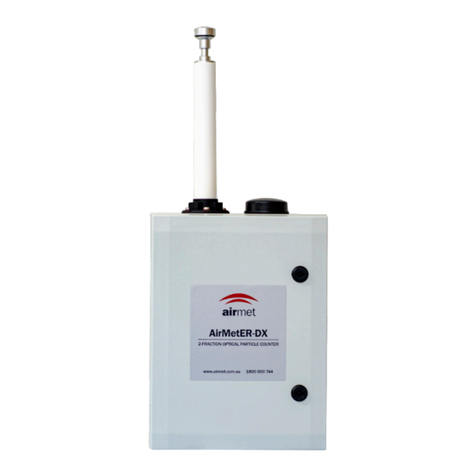
Air-Met AirMetER-AX User manual

1
AIR-MET SCIENTIFIC
AirMetER-AX
MULTI-PARAMETER
ENVIRONMENTAL MONITORING
STATION
Service Guide
Before operating the unit, please read this service guide thoroughly and retain for future reference
Revision 1 | November 2023

2
CONTENTS
Copyright Notice .........................................................................................................................................................3
Warnings, Cautionary Statements & Important Information .....................................................................................3
Warranty & Service.....................................................................................................................................................4
1. Filter Exchange........................................................................................................................................................5
2. TSP Head & Heated Inlet Cleaning ..........................................................................................................................6
3. Flow Rate Calibration..............................................................................................................................................7
DX II Flow Rate Calibration .....................................................................................................................................7
DX IV Flow Rate Calibration ....................................................................................................................................7
4. Installation ..............................................................................................................................................................8
Conditions Of Use ...................................................................................................................................................8
Location & Mounting Of Monitor ...........................................................................................................................9
5. Module & Part Removal/Replacement.................................................................................................................10
DXII Particulate Sensor Module Removal & Replacement ...................................................................................10
DXIV Particulate Sensor Module Removal & Replacement ..................................................................................11
Heated Inlet Removal & Replacement..................................................................................................................12
6. Frequency Tables ..................................................................................................................................................13
Calibration Frequency...........................................................................................................................................13
Filter Replacement................................................................................................................................................13
Module Replacement............................................................................................................................................13
7. Instrument Layout.................................................................................................................................................14
AirMetER-AX II Layout...........................................................................................................................................14
AirMetER AX-IV Layout .........................................................................................................................................15
8. Troubleshooting Guide .........................................................................................................................................16
9. Spare Parts ............................................................................................................................................................18
Contact Information..................................................................................................................................................19

3
COPYRIGHT NOTICE
These help materials or any part thereof may not, without the written consent of Air-Met Scientific, be copied,
reprinted, or reproduced in any material form including but not limited to photocopying, transcribing,
transmitting, or storing it in any medium or translating it into any language, in any form or by any means, be it
digitally, electronic, mechanical, xerographic, optical, magnetic, or otherwise.
The information contained in this document is proprietary and confidential and all copyright, trademarks, trade
names, patents, and other intellectual property rights in the documentation are the exclusive property of Air-Met
Scientific unless otherwise specified. The information (including but not limited to data, drawings, specification,
documentation, software listings, source or object code) shall not at any time be disclosed directly or indirectly to
any third party without prior written consent.
The information contained herein is believed to be accurate and reliable. Air-Met Scientific accepts no
responsibility for its use by any means or in any way whatsoever. Air-Met Scientific shall not be liable for any
expenses, costs by damage that may result from the use of the information contained within this document.
Although every effort is made to ensure accuracy, the specifications of this product and the content herein are
subject to change without notice.
WARNINGS, CAUTIONARY STATEMENTS & IMPORTANT
INFORMATION
Throughout this manual any warnings, cautionary statements or notes of importance are identified using the
following symbols:
IMPORTANT INFORMATION

4
WARRANTY & SERVICE
Air-Met Scientific maintains instrument service facilities nationwide. Should your instrument require service, you
may contact us on 1800 000 744 or at [email protected]. Alternatively, instrument service may be booked
by completing our online service request form at the following URL:
https://www.airmet.com.au/services/book-a-service
For non-warranty repairs, you will need to provide a purchase order number. All instruments submitted for
repair will undergo evaluation by a service technician and a quote for works required will be issued, for approval,
before any service proceeds.
Please note that, if a service quote is declined, a small charge for instrument assessment may apply.
Air-Met Scientific’s policy is to perform all repairs required to restore the instrument to full operating condition,
including replacement of sensors and batteries (as applicable) that have exceeded the recommended service life
and the completion of any manufacturer issued service dispositions.
The unit for repair may be sent to your local Air-Met Scientific branch office. Pack the instrument and all its
accessories (preferably in its original packing). Include any special instructions, your contact and company details
and a description of the fault. Repairs are warranted for 90 days from the date of shipment. Sensors and other
consumables have individual warranties.
Air-Met Scientific assumes no liability for work performed by unauthorised service
facilities.
The product specified in this manual is warranted against faulty workmanship for a period of 12 months, from
the date of dispatch.
Our obligation assumed under this warranty is limited to the replacement of parts which, by our assessment, are
proved to be defective and have not been misused, carelessly handled, defaced or damaged due to incorrect
installation or operation. This warranty is VOID where the unit has been tampered with or if repairs have been
made or attempted by anyone except an authorised representative of the manufacturing company.
Products for attention under the terms of this warranty (unless otherwise agreed) must be returned to the
manufacturer, freight paid and, if accepted for free repair, will be returned to the customers address in Australia
free of charge.
When returning the product for service or repair a full description of the fault and the conditions of operation
when the product failed must be given. In any event the manufacturer has no other obligation or liability beyond
replacement or repair of this product. Modifications may be made, by the manufacturer, to any existing or future
models of the unit as it may deem necessary without incurring any obligation to incorporate such modifications
in units previously sold or to which this warranty may relate.

5
1. FILTER EXCHANGE
The AirMetER-AX can contain up to four filters:
9933-05-CQ - Dust filter
1756-K-EACH - Gas filter
KAM-SF9 - NOx filter
121-5866 - Pneumatic silencer
It is recommended that these filters be exchanged no less than annually. The filters should be monitored and
inspected at regular intervals in new applications to gain an insight into how long the filters last before
discolouration.
It should be noted that the frequency of filter exchanges may be affected by the
application and location of the device.
The dust filter (Figure 1.4 –applicable only to the AirMetER-AXII) is located in the dust flow path between the
outlet of the particulate sensor module and the inlet of the top particulate pump module. After completing the
filter exchange, it is important to again validate the heated inlet flow rate to ensure no leaks have been created
during this process. The heated inlet flow rate is set to 2L/m ± 5%, as detailed in the flow rate calibration section
below.
The gas (Figure 1.3) and NOx filters (Figure 1.2) are located in the gas flow path, the gas filter is connected in line
at the gas inlet, the NOx filter is connected in line just before the ozone sensor module (Air-MetER AX-3). Once
these filters have been exchanged the flow rate of the gas path must be verified. The gas path flow rate should
be 0.85L/m ±5%, this process is described in the flow rate calibration section (page 7).
The pneumatic silencer (Figure 1.5) is screwed into the enclosure at the bottom of the instrument in between the
gas inlet and the gas/dust outlet. It can be removed by unscrewing it anti-clockwise and then replaced with the
new silencer, being careful to ensure the O-ring does not fall off from the silencer.
Figure 1.2 - NOx Filter
Figure 1.4 - Dust Filter
Figure 1.3 - Gas Filter
Figure 1.5 - Pneumatic Silencer
Figure 1.1 - Complete assembly
(parts may vary)
Other manuals for AirMetER-AX
1
Table of contents
Other Air-Met Laboratory Equipment manuals
Popular Laboratory Equipment manuals by other brands

Belden
Belden HIRSCHMANN RPI-P1-4PoE installation manual

Koehler
Koehler K1223 Series Operation and instruction manual

Globe Scientific
Globe Scientific GCM-12 quick start guide

Getinge
Getinge 86 SERIES Technical manual

CORNING
CORNING Everon 6000 user manual

Biocomp
Biocomp GRADIENT MASTER 108 operating manual