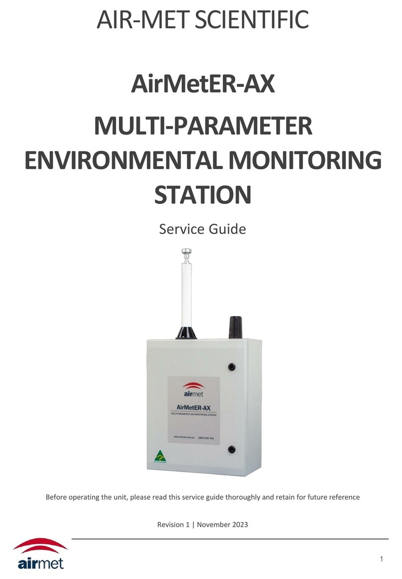
Air-Met AirMetER-DX User manual

1
AIR-MET SCIENTIFIC
AirMetER-DX
2-FRACTION PARTICULATE
MONITOR
User
Manual
Before operating the unit, please read this user manual thoroughly and retain for future reference
Edition 7 | June 2023

2
CONTENTS
Copyright Notice .........................................................................................................................................................3
Warnings, Cautionary Statements & Important Information .....................................................................................3
Warranty & Service.....................................................................................................................................................4
1. Overview.................................................................................................................................................................5
2. Monitor Assembly...................................................................................................................................................6
Hardware V.2 ..........................................................................................................................................................6
Hardware V.3 ..........................................................................................................................................................7
3. Detector Labeling....................................................................................................................................................8
4. Installation ..............................................................................................................................................................9
Conditions Of Use ...................................................................................................................................................9
Location & Mounting Of Monitor .........................................................................................................................10
5. LiveSense Cloud Portal..........................................................................................................................................11
6. Maintenance.........................................................................................................................................................12
Maintenance Frequency .......................................................................................................................................12
Troubleshooting....................................................................................................................................................13
Filter Exhange .......................................................................................................................................................13
TSP Head Cleaning ................................................................................................................................................14
Flow Rate Calibration............................................................................................................................................14
Frequency Tables ..................................................................................................................................................15
Annual Calibration ................................................................................................................................................16
7. Field K Factor Adjustment.....................................................................................................................................17
8. Performance .........................................................................................................................................................18
9. Spare Parts & Accessories.....................................................................................................................................19
10. Specifications ......................................................................................................................................................20
Contact Information..................................................................................................................................................19

3
COPYRIGHT NOTICE
These help materials or any part thereof may not, without the written consent of Air-Met Scientific, be copied,
reprinted, or reproduced in any material form including but not limited to photocopying, transcribing,
transmitting, or storing it in any medium or translating it into any language, in any form or by any means, be it
digitally, electronic, mechanical, xerographic, optical, magnetic, or otherwise.
The information contained in this document is proprietary and confidential and all copyright, trademarks, trade
names, patents, and other intellectual property rights in the documentation are the exclusive property of Air-Met
Scientific unless otherwise specified. The information (including but not limited to data, drawings, specification,
documentation, software listings, source or object code) shall not at any time be disclosed directly or indirectly to
any third party without prior written consent.
The information contained herein is believed to be accurate and reliable. Air-Met Scientific accepts no
responsibility for its use by any means or in any way whatsoever. Air-Met Scientific shall not be liable for any
expenses, costs by damage that may result from the use of the information contained within this document.
Although every effort is made to ensure accuracy, the specifications of this product and the content herein are
subject to change without notice.
WARNINGS, CAUTIONARY STATEMENTS & IMPORTANT
INFORMATION
Throughout this manual any warnings, cautionary statements or notes of importance are identified using the
following symbols:
IMPORTANT INFORMATION

4
WARRANTY & SERVICE
Air-Met Scientific maintains instrument service facilities nationwide. Should your instrument require service, you
may contact us on 1800 000 744 or at [email protected]. Alternatively, instrument service may be booked
by completing our online service request form at the following URL:
https://www.airmet.com.au/services/book-a-service
For non-warranty repairs, you will need to provide a purchase order number. All instruments submitted for
repair will undergo evaluation by a service technician and a quote for works required will be issued, for approval,
before any service proceeds.
Please note that, if a service quote is declined, a small charge for instrument assessment may apply.
Air-Met Scientific’s policy is to perform all repairs required to restore the instrument to full operating condition,
including replacement of sensors and batteries (as applicable) that have exceeded the recommended service life
and the completion of any manufacturer issued service dispositions.
The unit for repair may be sent to your local Air-Met Scientific branch office. Pack the instrument and all its
accessories (preferably in its original packing). Include any special instructions, your contact and company details
and a description of the fault. Repairs are warranted for 90 days from the date of shipment. Sensors and other
consumables have individual warranties.
Air-Met Scientific assumes no liability for work performed by unauthorised service
facilities.
The product specified in this manual is warranted against faulty workmanship for a period of 12 months, from
the date of dispatch.
Our obligation assumed under this warranty is limited to the replacement of parts which, by our assessment, are
proved to be defective and have not been misused, carelessly handled, defaced or damaged due to incorrect
installation or operation. This warranty is VOID where the unit has been tampered with or if repairs have been
made or attempted by anyone except an authorised representative of the manufacturing company.
Products for attention under the terms of this warranty (unless otherwise agreed) must be returned to the
manufacturer, freight paid and, if accepted for free repair, will be returned to the customers address in Australia
free of charge.
When returning the product for service or repair a full description of the fault and the conditions of operation
when the product failed must be given. In any event the manufacturer has no other obligation or liability beyond
replacement or repair of this product. Modifications may be made, by the manufacturer, to any existing or future
models of the unit as it may deem necessary without incurring any obligation to incorporate such modifications
in units previously sold or to which this warranty may relate.

5
1. OVERVIEW
The AirMetER-DX is a remote area dust monitor for the simultaneous detection and measurement of particulate
matter PM2.5 and PM10 size fractions.
Housed in a weatherproof IP66 rated polycarbonate enclosure, the AirMetER-DX is ideal for continuous round
the clock outdoor monitoring and has data logging capacity at a minimum of 365 days at one-minute intervals. It
has a built-in log and forward capability to capture one week of operation in the event of a network disruption.
An aluminium heated inlet with TSP head minimises the detrimental effect of humidity on the accuracy of dust
measurement.
Integrating seamlessly with the LiveSense cloud portal for remote data access, this secure data portal enables
users to access monitoring logs, set customisable alerts, manage monitoring reports and more. The web-service
application is accessible on both desktop PC and mobile smart devices.
The AirMetER-DX should be powered on 12VDC and is available with an optional Bluetooth enabled solar-power
system that can provide up to 5 days autonomous operation.
For mains powered applications, an IP67 rated, 240VAC to 12VDC, 5A power supply is available.
AirMetER-DX | Proudly Australian Made

6
2. MONITOR ASSEMBLY
HARDWARE V.2

7
HARDWARE V.3

8
3. DETECTOR LABELING
Each detector is identified with the use of two labels. The labels contain the part and serial number information
(Figure 3.1).
The labels can be located on the inside surface of the instrument door and on top of the particulate module.
MODEL: AirMetER-DX
SERIAL NO.: ER0917010
ICCID: 69852470001478955472
POWER: 12VDC
CB: 4A
MODBUS: 1
Figure 3.1 –Monitor Product Label Example
Information on these labels may be required for technical support requests.

9
4. INSTALLATION
Use of the AirMetER-DX monitor in applications contrary to the conditions of
use criteria may present a safety risk and/or void any instrument warranty.
CONDITIONS OF USE
The AirMetER-DX is:
i. NOT certified for use in hazardous area classified zones.
ii. NOT designed for ensuring safety of personnel and equipment.
The AirMetER-DX is supplied with brackets pre-fitted to support standard pipe-clamp pole mount inserts suitable
for installation on standard masts or poles ranging from 40-105mm in diameter. An adjustable spanner or flat-
blade screwdriver may be utilised to either tighten or release the pipe clamp to suit the intended structure
diameter. Care should be taken during installation to ensure the AirMetER-DX is level and firmly secured.
Figure 4.1 –Mounting Brackets
Figure 4.2 –Pre-Fitted Brackets

10
LOCATION & MOUNTING OF MONITOR
Air-Met Scientific recommends the monitor is pole or tripod mounted in an open area, free from
buildings and other obstructions that may have an influence on measurements.
Figure 4.3 –External and Mounting-Point Dimensions (mm)

11
11
5. LIVESENSE CLOUD PORTAL
To access the LiveSense cloud platform, enter https:// airmetapp.livesense.com.au/login
into your browser and
sign in using the credentials provided to you by your administrator.
The username is generally your e-mail address, unless specified otherwise. If you cannot remember your
password, you may utilise the ‘forgot password’function to reset this.
By default, this station will be setup with an activity alarm ‘Comms Alarm’ and basic graphical widgets on your
dashboard.
Should you wish to modify your platform, please refer to Air-Met Scientific’s ‘LiveSense User Guide’for a
complete overview of basic and more advanced functions available.
For further assistance or troubleshooting, contact engineeredsolutions@airmet.com.au

12
6. MAINTENANCE
MAINTENANCE FREQUENCY
Air-Met Scientific recommends a maximum maintenance interval of 12 months.
Specified maintenance and calibration intervals are recommendations only. A
maintenance plan suitable for the application should be discussed internally.
Alternatively, Air-Met Scientific can assist with this through a service agreement.
Only trained technicians should attempt any disassembly or repairs on the AirMetER-DX.

13
13
TROUBLESHOOTING
ISSUE
SOLUTIONS
I. No air flow at the exhaust
1. Is the pump plugged in at the top as displayed in Figure: 6.5?
2. Is the dust filter blocked and need replacement?
3. Trace the tubing from the heated inlet > particulate sensor
module > dust filter > pump module > external exhaust for
any signs of leaks or blockages.
4. Follow the Flow Rate Calibration section (page 14) below to
adjust the flow rate.
II. Air flow at the inlet not within
the 2L/m ±5% allowable range
1. Is the dust filter blocked and need replacement?
2. Is the pump plugged in at the top as displayed in Figure: 6.5?
3. Are the heated inlet and particulate sensor modules connected
by the tube adapter?
4. Trace the tubing from the heated inlet > particulate sensor
module > dust filter > pump module > external exhaust for
any signs of leaks or blockages.
5. Follow the Flow Rate Calibration section (page 14) below to
adjust the flow rate.
III. Readings are low
1. Is the instrument due for calibration or service?
2. Is the dust filter polluted and need replacement?
3. Is the pump plugged in at the top as displayed in Figure: 6.5?
4. Is the heated inlet and particulate sensor module connected
by the tube adapter?
5. Trace the tubing from the heated inlet > particulate sensor
module > pump filter > pump module > external exhaust for
any signs of leaks or blockages.
6. Follow the Flow Rate Calibration section (page 14) below to
adjust the flow rate.
IV. Pump not running
1. Is the pump plugged in at the top as displayed in Figure: 6-5?
2. Is the modem on? If both the modem and pump are not on,
then the unit may not be powered on.
3. Check the fuse / circuit breaker and power supply.
V. Data not uploading to
LiveSense
1. Is the modem plugged in?
2. Check the fuse / circuit breaker and power supply.
3. Is the uSD card installed in the easylog? (Hardware V.3)
4. Does the instrument have connection to the internet
through your specific connection method? (Cellular, Wi-Fi or
ethernet)
5. Is the cellular or Wi-Fi antenna correctly installed?
VI. Instrument not turning on
1. Check the fuse / circuit breaker and power supply.
2. Using a multimeter, check that the instrument is receiving
12VDC from the power supply.

13
FILTER EXHANGE
The AirMetER-DX contains up to two filters:
9933-05-CQ –Dust filter
121-5866 –Pneumatic silencer
The pneumatic silencer is installed on AirMetER-DX instruments manufactured before February 2023. This only
requires replacement when polluted or damaged. It is recommended that the dust filter be exchanged no less
than annually. The filters should be monitored and inspected at regular intervals in new applications to gain an
insight into how long the filters last before discolouration.
It should be noted that the frequency of filter exchanges may be affected by the
application and location of the device.
The dust filter is secured to the tubing with push fittings. Compress the push fitting to release the filter from the
fitting. Ensure when installing the new filter to properly click the filter in place into both push fittings, keeping the
directional arrow pointing towards the pump.
After completing the pump filter exchange, it is important to again validate the inlet flowrate to ensure no leaks
have been created during this process. The inlet flowrate is set to 2L/m ±5%, as detailed in the flowrate
calibration section below (PAGE 14).
The pneumatic silencer can be removed by unscrewing it anti-clockwise before replacing it with the new silencer.
Take care to ensure the O-ring does not fall off the new silencer when replacing.
Figure 6.1 –Complete assembly
Figure 6.2 –Dust Filter
Figure 6.3 –Pneumatic Silencer

14
TSP HEAD CLEANING
A TSP head should be installed on all heated inlets at factory and while installed in
the field, these need to be periodically cleaned. The time interval between
cleaning varies depending on the application and location of the device. It is
recommended to clean and check for any blockages within the TSP head and
heated inlet assembly during annual routine maintenance.
Some instruments will have a PM10 sharp cut cyclone (AE10-2) installed instead of
the standard TSP head. These are used in applications where high levels of
particulates larger than PM10 are found and need to be filtered out as to not
damage the sensor. When the sharp cut cyclone is being used, it needs to be
monitored and cleaned at a much higher frequency.
This process may be completed using a brush and compressed air if available.
FLOW RATE CALIBRATION
Attach a 0.4-5L/m rotameter (320-4A5) to the inlet of the AirMetER-DX. The flowmeter should indicate 2L/m
±5%. Should this be out of tolerance, check to ensure there are no leaks and that there is pressure when blocking
the heated inlet. Manual adjustment of the pump flow meter may be completed to achieve this as depicted
below.
Unscrew 4x PH screws from the AirMetER AX-P top case (NOTE: these screws are retaining).
Figure 6.5 –Pump Top
Figure 6.6 –Pump Internal
Figure 6.7 –Pump Control Internal
Using a small flat-blade driver, remove the lid from the control box within the pump module.
Adjust the potentiometer clockwise to increase the flowrate and anti-clockwise to decrease the flowrate in order
to achieve 2L/m ± 5%.
In the event the flowrate cannot maintain 2L/m ± 5% at the inlet, losses can be diagnosed through-out the flow
path: Heated inlet > particulate sensor module > dust filter > pump module > external exhaust
Figure 6.4 –TSP Head

15
FREQUENCY TABLES
CALIBRATION FREQUENCY TABLE
FILTER REPLACEMENT TABLE
FILTER DESCRIPTION
PART NUMBER
REPLACEMENT FREQUENCY
Dust Filter
9933-05-CQ
Yearly*
Pneumatic Silencer
121-5866
Only when polluted or damaged
*Dependent on the application of the instrument
MODULE REPLACEMENT TABLE
MODULE DESCRIPTION
PART NUMBER
RECOMMENDED REPLACEMENT CYCLE
Particulate Sensor
AMS-SDS011
2 years
Pump
TM30A-D12-V7004
2 years
DESCRIPTION
CALIBRATION FREQUENCY
Particulate Sensor
Yearly
Pump Module
Yearly (additionally when the dust filter is replaced or the
heated inlet is removed)

16
ANNUAL CALIBRATION
In order for the AirMetER-DX module to be calibrated, it must be returned to the Air-Met Scientific Head Office in
Melbourne. For a guide on how to remove the AirMetER-DX or pump modules, please refer to our Module
Removal / Replacement quick guide or Service Guide.
Air-Met Service Facilities perform repairs and part services, as well as calibrations and adjustments. Air-Met
Scientific offers calibration reminder programs and maintenance contracts for the AirMetER-DX.
For further details, please feel free to contact us at any of the following means:
1800 000 744
engineeredsolutions@airmet.com.au
www.airmet.com.au
Alternatively, scan the QR code to locate your nearest Air-Met Scientific office.

17
7. FIELD K FACTOR ADJUSTMENT
Field calibration (K Factor Adjustment) of the AirMetER-DX is an important process to ensure data accuracy with
respect to the location of the instrument. Field calibration should not be considered a substitute for factory
calibration.
In order to perform a K Factor adjustment, a gravimetric sample must be collected relative to the newly installed
instrument.
NOTE: Ensure correct methods for conducting a gravimetric sample are followed to ensure an accurate K Factor
adjustment –If unsure regarding this process please contact Air-Met Scientific.
Provide collected data to Air-Met Scientific and a K Factor adjustment may be completed remotely.

18
8. PERFORMANCE
R² = 0.9501
-50
0
50
100
150
200
250
300
350
400
450
µg/mᶟ
AirMetER-DX / Dusttrak 8530 PM10 Correlation
R² = 0.9058
-50
0
50
100
150
200
250
300
350
400
µg/mᶟ
AirMetER-DX / Dusttrak 8530 PM2.5 Correlation

19
9. SPARE PARTS & ACCESSORIES
ITEM
PART NUMBER
Tripod
TF-TRI-AM
Remote Power System
AMS/200S/170B/15M/9C or AMS/200S/150B/15M/9C
TSP Head
10085
PM10 Cyclone Head
AE10-2
Heated Inlet
10090-2
Power Supply (240V)
LPF-60-12-AUP
Pneumatic Silencer
121-5866
Dust Filter
9933-05-CQ
Pump
TM30A-D12-V7004
Meteorological Sensors
Upon Request
Luer Fittings and Tubing
Upon Request
Particulate Sensor
AMS-SDS011
0.4L –5L Rotameter
320-4A5
Other manuals for AirMetER-DX
2
Table of contents
Other Air-Met Laboratory Equipment manuals
Popular Laboratory Equipment manuals by other brands

Cognionics
Cognionics Quick Series manual

SKC
SKC biosampler 225-9595 operating instructions

logos biosystems
logos biosystems LUNA FX7 Series user manual

Amphenol
Amphenol Kaye CTR-40 user guide

Aqua Ultraviolet
Aqua Ultraviolet Classic Series Replacement

Analytik Jena
Analytik Jena novAA 800 operating manual

Dosmatic
Dosmatic Advantage A20-10% Installation & operating instructions

WPI
WPI PV850 instruction manual

OPENTEXT
OPENTEXT Tableau TX1 user guide

RBCBioscience
RBCBioscience MagCore HF48 Operation manual

Elma
Elma Elmasonic S50R operating instructions

Centurion Scientific
Centurion Scientific PrO-Hospital Ambient instruction manual