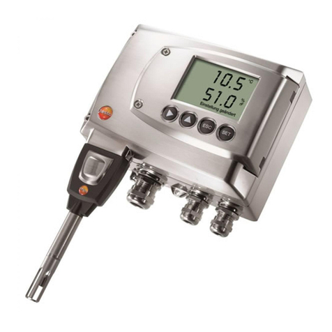
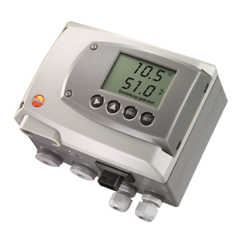
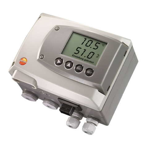
TESTO 6682 User manual

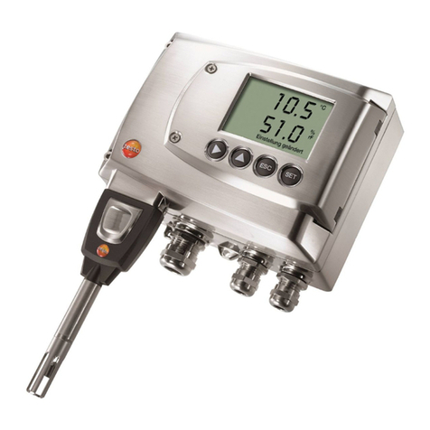
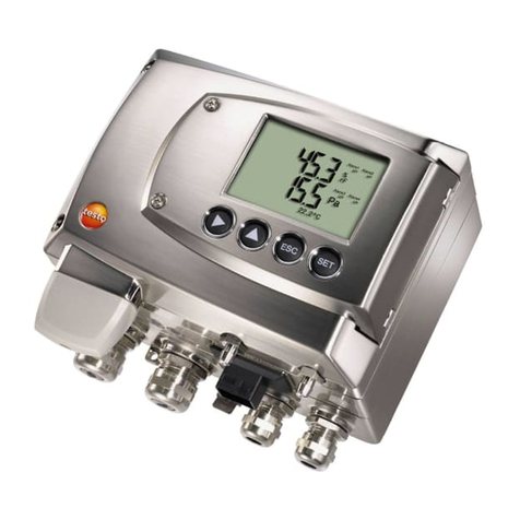
testo 6682 Humidity transmitters
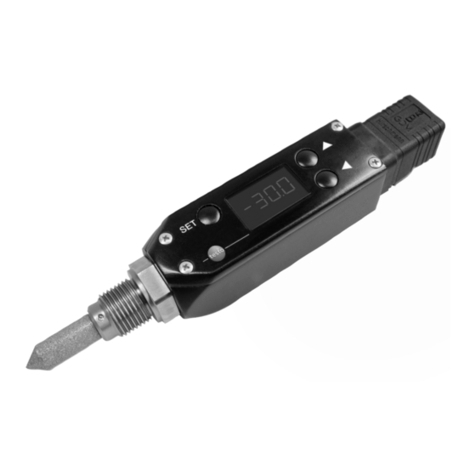
testo 6616 Probes
For use in areas with risk of explosion according to
Directive 94/9/EC (ATEX)
Instruction manual en

2 Safety
Notes for installation
►Observe the installation and safety instructions from the instruction
manual.
►Perform the installation according to the manufacturer's specifications
and the valid standards and regulations.
►Only use the instruments in measurement substances against which the
materials that come in contact with the medium are sufficiently resistant.
►Observe the maximum process conditions according to the instruction
manual at hand.
►Observe the regulations for the interconnection of intrinsically safe
circuits according to EN 60079-14 (proof of intrinsic safety).
►Close unused entry openings with suitable sealing plugs.
►Properly install the housing cover and cable entries to maintain the
housing protection class.
►Integrate the transmitter and the probe into the equipotential bonding.
►Avoid an electrostatic charge, e.g. due to friction, cleaning, maintenance
or similar.
►Only clean plastic surfaces with a moist cloth.

Safety 3
Safety
Installation, electrical connection, commissioning, operation and maintenance
of the measuring system can only be performed by trained personnel
authorized by the system operator. The trained personnel must have read
and understood this instruction manual and follow the directions specified
within it. Changes and repairs can only be performed on the instrument if this
is permitted according to the instruction manual.
If using the measuring system in areas with risk of explosion, the
corresponding national standards and specifications are to be complied with.
Separate safety instructions are included with the measuring system and are
an inherent part of this documentation. The installation specifications,
connected loads and safety instructions contained must be observed. The
trained personnel must be sufficiently skilled. The measuring and safety-
related requirements for the measuring points are to be complied with.
Avoiding electrical hazards
►Never use the instrument and connected probes to measure on or near
live parts!
►Damaged mains cables must only be replaced by authorized personnel.
►Only have the transmitter wired and connected by authorized personnel
with the voltage disconnected.
►You must always comply with the regulations applicable in your country
to the opening and repair of electrical equipment.
Avoiding personal injury/damage to equipment
►Installation, setting and calibration work must only be carried out by
qualified and authorized personnel!
►Only open the instrument when this is expressly described in the
instruction manual for installation, maintenance or repair purposes.
►Observe the permissible storage, transport and operating temperatures.
►Never store or operate the product with solvents and do not use any
desiccants.
►Do not use the instrument for control purposes at the same time as
operating or servicing the transmitter.
►Only operate the product properly, for its intended purpose and within the
parameters specified in the technical data. Do not use force.

4 Environment
►Carry out only the maintenance and repair work that is described in the
documentation. Follow the prescribed steps exactly. Use only OEM spare
parts from testo.
Environment
Protecting the environment
►Send the product back to testo at the end of its useful life. We will ensure
that it is disposed of in an environmentally friendly manner.

About this document 5
About this document
►Please read this documentation through carefully and familiarize yourself
with the product before putting it to use. Keep this document to hand so
that you can refer to it when necessary. Hand this documentation on to
any subsequent users of the product.
►The following conventions are followed in this document:
Character/
display:
Explanation/example
With the signal word Warning!:
Warns against hazards which could result in serious physical
injury if the precautionary measures indicated are not taken,
e.g.:
De-energize the mains connection before connecting the
transmitter!
With the signal word Ex protection!:
Safety instructions for using in area with risk of explosion.
For this, also observe the separate safety instructions for
electrical operating equipment for areas with risk of
explosion.
With the signal word Caution!:
Warns against hazards which could result in minor physical
injury or damage to equipment if the precautionary
measures indicated are not taken, e.g.:
Observe the permissible operating temperature!
Important information, e.g.:
Administrator rights are required to install the program under
Windows®2000, XP and Vista.

6 About this document
Character/
display:
Explanation/example
Aim of action, e.g.:
Assembling the instrument at the process
connection:
Requirement that must be met, e.g.:
The service flap is open.
1. Steps are numbered if a certain sequence of actions must
be followed, e.g.:
1. Loosen and remove housing screws.
2. Remove the upper part of housing.
A step is not numbered if there are no further steps or if the
step is optional, e.g.:
▪Insert probe connector into socket of testo 6682 until it
engages.
" ... " Example entries are in inverted commas, e.g.:
The value "0" results in ....
Bold type Elements of the program interface or instrument display,
e.g.:
The instrument designation appears in the
instrument/parameter file list.
Select Main Menu Channel 1 and confirm with SET.
CAPITAL
LETTERS
Keys on the instrument or keypad, e.g.:
Press ESC.

Contents 7
Contents
1TRANSMITTER............................................................................................9
1.1 Specifications...........................................................................................9
1.1.1 Functions and use.......................................................................9
1.1.2 Scope of delivery.........................................................................9
1.1.3 Accessories...............................................................................10
1.1.4 Technical data........................................................................... 10
1.1.5 Dimensions ...............................................................................11
1.1.6 EC declaration of conformity for testo 6682..............................12
1.2 Product description ................................................................................ 13
1.2.1 At a glance ................................................................................13
1.2.2 Usable probes ...........................................................................14
1.2.3 Display and keypad...................................................................14
1.2.4 Analog outputs ..........................................................................14
1.2.5 Parameters................................................................................15
1.2.6 Scaling ......................................................................................15
1.3 Commissioning ......................................................................................17
1.3.1 Wall mounting ...........................................................................17
1.3.2 Connecting the instrument ........................................................19
1.3.3 Adjusting the instrument............................................................25
1.4 Operation ...............................................................................................32
1.4.1 Key cover ..................................................................................32
1.4.2 Password protection..................................................................33
1.4.3 Structure of user menu..............................................................33
1.4.4 Overview of the testo 6682 user menu............................................35
1.4.5 The individual main menus .......................................................37
1.5 Status, warning and error messages..................................................... 48
1.5.1 Status messages....................................................................... 48
1.5.2 Transmitter warning messages.................................................49
1.5.3 Error messages.........................................................................50
1.6 Maintenance and cleaning.....................................................................51
1.6.1 Maintaining the instrument........................................................51
1.6.2 Cleaning the instrument ............................................................51

8 Contents
2TESTO 6616 PROBES ............................................................................... 52
2.1 Specifications......................................................................................... 52
2.1.1 Functions and use..................................................................... 52
2.1.2 Scope of delivery ...................................................................... 54
2.1.3 Accessories............................................................................... 55
2.2 Product description................................................................................ 55
2.2.1 Filter .......................................................................................... 55
2.2.2 testo 6616 cable probe ............................................................. 56
2.2.3 EC declaration of conformity for testo 6616.............................. 61
2.3 Commissioning ...................................................................................... 62
2.3.1 Installing the probe.................................................................... 62
2.3.2 Connecting/removing the probe to/from the transmitter ........... 64
2.4 Maintenance and cleaning..................................................................... 65
2.4.1 Exchanging filter protection cap for testo 6616 probe .............. 65
2.4.2 Cleaning the instrument and filter protection cap .....................66
2.4.3 Exchanging probe ..................................................................... 66
3TIPS AND ASSISTANCE ............................................................................. 67
3.1 Questions and answers ......................................................................... 67
3.2 Accessories and spare parts ................................................................. 68
3.2.1 Ordering options for testo 6682 transmitter (0555 6682).................... 69
3.2.2 Ordering options for testo 6616 probes (0555 6616)................ 71

testo 6682 - 1.1 Specifications 9
1 Transmitter
1.1 Specifications
1.1.1 Functions and use
The testo 6682 humidity transmitter is used in conjunction with the plug-in,
adjusted testo 6616 probe.
Please refer to Chapter testo 6616 probe, page 52 for
information about commissioning, operating and maintaining
the testo 6616 probe.
The testo 6682 humidity transmitter is suitable for the following applications,
for example:
Ex areas: see separate safety instructions and model inspection
certification
Process instrumentation
Clean rooms
Test benches
Drying processes
Production and storage air quality
Complex room climate applications.
1.1.2 Scope of delivery
The scope of delivery of the testo 6682 humidity transmitter includes the
following:
Transmitter
Key cover
Rear panel bracket
Calibration protocol
Operating instructions
Transmitter safety instructions

10 testo 6682 - 1.1 Specifications
1.1.3 Accessories
The following accessories are available for the testo 6682 humidity
transmitter:
Protection caps for probes
Assembly accessories
Information about accessories and their order numbers can
be found in Chapter Accessories and spare parts, page 68 or
on the website at www.testo.com.
1.1.4 Technical data
Parameters
- Humidity (various variables and
units)
- Temperature (°C/°F)
Measuring range
- Humidity: 0 to 100 % RH
- Temperature: -30 to + 150 °C/
- 22 to + 302 °F
Accuracy
- ± 1 % RH; ± 0.15 °C/± 0.30 °F
Resolution
- 0.1 % RH; 0.01 °C/0.01 °F
Meas. cycle
- 1/sec
Voltage supply
- 2-wire: 4 to 20 mA, current loop
from certified, intrinsically safe
power supply units:
U0= 28 V
I0= 93 mA
P0= 650 mW
Analog output
- 4 to 20 mA ± 0.03 mA (2-wire)
- (plus fault through supply isolator)
Resolution of analog output
- 12 bit
Display
- 2-line LCD with plain text line
Housing operating temperature
- with display from -20 to 70 °C/
- -4 to + 158 °F
Storage temperature
- -40 to 80 °C/-40 to +176 °F
Materials
- Housing: chrome plated die-cast
zinc
- Display: Plastic
- Keypad: Plastic
- Housing screws: Stainless steel
- Screws rear wall fixture:
Galvanized steel
- Rear wall fixture: Plastic
- Screws: Galvanized brass
- Plugs: Metal
- Earth terminal: Stainless steel
- Sealing rings: Plastic
- Label cover: PET
Weight
- 2.01 kg/4.33 lb

testo 6682 - 1.1 Specifications 11
Protection class
- IP 65 only if the transmitter is wired
and/or seal plugs are inserted and
the probe is plugged in
Directives, standards and tests
- 94/9/EC (ATEX)
- EC Directive: 2004/108/EC
Warranty
- Duration: 2 years
- Warranty conditions, see
www.testo.com/warranty
1.1.5 Dimensions

12 testo 6682 - 1.1 Specifications
1.1.6 EC declaration of conformity for testo
6682

testo 6682 - 1.2 Product description 13
1.2 Product description
1.2.1 At a glance
1 Keys (with display)
2 Service flap screw connection
(self-locking, 2x)
3 Display
4 Service flap
5 M 16 x 1.5 screw connection,
cable entry
6 M 16 x 1.5 screw connection,
cable entry
7 Earthing/PE connection
8 Eyelet for measuring point panel
9 Probe connector (testo 6616)
10 Upper part of housing
11 Housing screws
12 Socket for probe connector
13 Hole for fastening to rear panel
bracket (M3 x 6 screw)
14 Plastic bracket for assembly on
rear panel

14 testo 6682 - 1.2 Product description
1.2.2 Usable probes
The testo 6682 humidity transmitter can be used with the testo 6616 probe:
Probes Article no. Characteristic
testo 6616 0555 6616 Cable probe version; accuracy to ± 1 % RH;
temperature range -30 °C to +150 °C/-22 to
+302 °F, sensor soldered
1.2.3 Display and keypad
The testo 6682 humidity transmitter is operated via four keys together with
the display.
The LCD display consists of two 7-segment lines for displaying readings and
units and of an information line (for status messages, for example).
Brightness and contrast of the display can be changed via the user menu.
1.2.4 Analog outputs
As analog outputs the testo 6682 has 2 current outputs of 4 to 20 mA (2-
wire), where channel 1 is used for the supply.
Ex protection!
The testo 6682 transmitter is intended for use in areas with
risk of explosion. The analog outputs (simultaneously also
power supply) can only be operated using certified,
intrinsically safe power supply units.

testo 6682 - 1.2 Product description 15
1.2.5 Parameters
The following parameters are calculated:
Relative humidity in %RH (technical)
Relative humidity in % WMO* (calculation according to the WMO
standard)
Temperature °C and °F
Dewpoint or pressure dewpoint in °Ctd and °Ftd*
Absolute humidity in g/m³ and gr/ft³
Degree of humidity in g/kg and gr/lb
Enthalpy in kJ/kg and BTU/lb
Psychrometer temperature in °Ctw and °Ftw
Water vapour partial pressure in hPa and "H2O
Water content in ppmvol and % vol
Dewpoint of H2O2mixture in °Ctm and °Ftm.
*It is possible that condensation appears as early as a displayed
humidity starting from 70 % and is shown on the display.
1.2.6 Scaling
There are three types of min./max. values:
1 The measuring range
The maximum sensor performance is in this range. Values outside of
the measuring range are displayed via messages, for example.
Measuring range, see table (below).
2 Standard scaling
The output signals are assigned to this measuring range as standard:
- during delivery if no entries are made in the order code
- after exchanging the unit, the measuring range recorded in the
instrument is applied as standard.
The transmitter even retains its scaling with the voltage
disconnected.

16 testo 6682 - 1.2 Product description
3 The maximum settings for the manual scaling
- the values are not expressly given in the table. The maximum limits
can be calculated as follows:
X = difference between MIN. and MAX. value of the standard scaling
(Max. value of standard) + (50 % of X)
(Min. value of standard) - (50 % of X)
- It is thus possible to scale beyond the measuring range, e.g. for the
adjustment of the scaling limits to standard values of a PLC.
Measuring ranges with testo 6616 probe
Parameter Unit
Measuring
range,
physical
at 1013 hPa
Standard
scaling
MUF
measuring
range
MIN MAX MIN MAX
Temperature °C -30
+150
-20
+150
°F -22
+302
-4
+302
Relative humidity % RH 0
+100
0
+100
WMO relative humidity % RH 0
+100
0
+100
Dewpoint/pressure dewpoint °Ctd -20
+100
-20
+100
°Ftd -4
+212
-4
+212
Absolute humidity g/m3 0
600
0
2000
gr/ft3 0
250
0
800
Degree of humidity g/kg 0
13300
0
9500
gr/lb 0
93000
0
66500
Enthalpy kJ/kg -40
99999
-40
8000
BTU/lb -18
43000
-18
3500
Psychrometer temperature °Ctw -40
100
-40
180
°Ftw -58
210
-40
356
Water content ppm vol H2O
0
99999
0
99999
% vol 0
40
0
40
Water vapour partial pressure
hPa 0
1000
0
7000
inchH2O 0
400
0
2800

testo 6682 - 1.3 Commissioning 17
1.3 Commissioning
1.3.1 Wall mounting
Attaching rear panel bracket
Ex protection!
Observe the general protective measures when working in
areas with risk of explosion.
1. Remove locking screw (item (4) of drawing on page 18) and detach
rear panel bracket from plastic bracket (item (2) of drawing on
page 18).
2. Hold rear panel bracket in assembly position and mark the three drill
holes.
3. Drill three holes (5 mm) and insert dowels.
4. Screw on rear panel bracket.
Remember that the clamping brackets (1) must face the wall.

18 testo 6682 - 1.3 Commissioning
Fastening instrument to rear panel bracket
1. Slide plastic bracket (2) on the back of instrument onto rear panel
bracket until it engages (see arrows).
2. Insert screw (4) through hole (3) and screw into rear panel bracket.
3. Insert probe connector (5) into socket until it engages.

testo 6682 - 1.3 Commissioning 19
1.3.2 Connecting the instrument
Ex protection!
Each of the two channels of the testo 6682 must be provided
with a certified transmitter power supply unit that provides a
category ia circuit.
The technical data of the transmitter power supply unit must
not exceed the following Ex-relevant data:
U0= 28 V
I0= 93 mA
P0= 650 mW.
For correct operation, the terminal voltage at the transmitter
must not fall below 16 V with 20 mA loop current.
Opening the instrument
1. Loosen screw connections (1) of service flap and open the flap.

20 testo 6682 - 1.3 Commissioning
2. Loosen and remove housing screws (2).
3. Remove upper part of housing from lower part (3) and place on a
clean surface.
Warning!
Electrical voltage.
Danger of injury!
De-energize the power supply before connecting the
transmitter!
Only have the transmitter wired and connected by authorized
personnel with the voltage disconnected.
Other manuals for 6682
1
Table of contents
Other TESTO Transmitter manuals