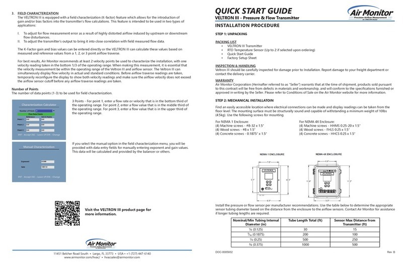
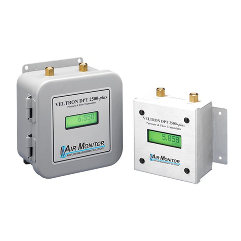
Air Monitor VELTRON II User manual

Installation, Operation,
and Maintenance Manual
VELTRON II
MicroprocessorBased
Pressure& Flow"Smart" Transmitter
Versions5.3X
Installation, Operation & Maintenance
Air Monitor Corporation provides complete
technical support between the hours of
7 a.m. and 5 p.m. PST, M-F
Contact our Service Department
Toll Free: 1-800-AIRFLOW
or fax us at 1-707-526-2825
Air Monitor Corporation
116-011-98.P65 (8/30/10) VELTRONII-IO&MManual


VELTRON II
Air Monitor Corporation
116-011-98.P65 (8/30/10) VELTRONII-IO&MManual
TABLEOFCONTENTS
INSTRUMENTWARRANTY ...................................................................................................................... i
SECTION1 – GENERALINFORMATION
1.1 DESCRIPTION ................................................................................................................................1
1.2 THEORYOFOPERATION .............................................................................................................. 1
SECTION2 – PERFORMANCESPECIFICATIONS
2.1 TRANSMITTER ............................................................................................................................... 2
2.2 INDICATION..................................................................................................................................... 2
2.3 INPUTS/OUTPUTS .......................................................................................................................... 2
2.4 POWER .......................................................................................................................................... 2
SECTION3 – FEATURES
3.1 OPERATOR SETUPMENU ............................................................................................................ 3
3.2 TRANSMITTERHOLD ..................................................................................................................... 3
3.3 AUTOMATICZEROING ................................................................................................................... 3
3.4 AUTO-purgeMANAGEMENT(option).............................................................................................. 3
3.5 ALARM(option)............................................................................................................................... 4
3.6 SPECIALFUNCTIONS(option) ....................................................................................................... 4
3.7 DATADISPLAY ............................................................................................................................... 5
3.8 K-FACTOR ...................................................................................................................................... 5
3.9 FLOW/DIFFERENTIALPRESSURECALCULATOR ........................................................................ 5
3.10 NETWORK...................................................................................................................................... 5
3.11 MULTIPLE OPERATING POWERSELECTIONS ............................................................................. 5
3.12 ENCLOSURE .................................................................................................................................. 5
SECTION 4 – INSTALLATION
4.1 RECEIVINGAND INSPECTION ....................................................................................................... 6
4.2 LOCATION ...................................................................................................................................... 6
4.3 MOUNTING ..................................................................................................................................... 6
4.4 PROCESSCONNECTIONS ............................................................................................................ 7
4.5 POWER/SIGNALCONNECTIONS ............................................................................................... 8-9
4.6 INPUT/OUTPUTSELECTION ........................................................................................................ 10
4.7 DISPLAYCONTRASTADJUSTMENT............................................................................................ 10
SECTION5 – OPERATION
5.1 INTRODUCTION .............................................................................................................................11
5.2 START-UP ......................................................................................................................................11
5.3 NORMALOPERATION.................................................................................................................. 12
5.4 CONFIGURATION ......................................................................................................................... 13
5.5 PUSHBUTTONDEFINITION .......................................................................................................... 14
5.6 CONFIGURATIONPROGRAMMING..........................................................................................15-17
5.7 OPERATORPASSWORDSELECTION ........................................................................................ 18
5.8 TRANSMITTERSCALING&CONFIGURATION .........................................................................19-26
5.9 LOW PASSFILTER SELECTION .................................................................................................. 27
5.10 AUTO-zeroCONFIGURATION ....................................................................................................... 28
5.11 AUTO-purgeCONFIGURATION ..................................................................................................... 29
5.12 AUTO-calibrationCONFIGURATION .............................................................................................. 30
5.13 ALARMCONFIGURATION ........................................................................................................31-32
TABLEOFCONTENTS

VELTRON II
TABLEOF CONTENTS
SECTION5 –OPERATION (con't)
5.14 CONTROLLERCONFIGURATION ................................................................................................. 32
5.15 SPECIALFUNCTIONCONFIGURATION ...................................................................................33-34
5.16 K-FACTORCONFIGURATION ...................................................................................................35-36
5.17 STANDARDDISPLAYCONFIGURATION ..................................................................................37-39
5.18 ENHANCEDDISPLAYCONFIGURATION..................................................................................40-44
5.19 ANALOGOUTPUTCONFIGURATION ........................................................................................... 45
5.20 TRANSDUCERSPANSELECTION ............................................................................................... 46
5.21 TRANSMITTERINPUTCALIBRATION ........................................................................................... 47
5.22 TRANSMITTEROUTPUTCALIBRATION ....................................................................................... 47
5.23 POWERSUPPLYCALIBRATION.................................................................................................. 48
5.24 TRANSDUCERCHARACTERIZATIONSELECTION....................................................................... 49
5.25 NETWORKCONFIGURATION....................................................................................................... 50
5.26 MENUINACTIVITYTIMEOUTSELECTION ................................................................................... 51
SECTION6 – CALIBRATION
6.1 REQUIREDEQUIPMENT .............................................................................................................. 52
6.2 PREPARATION ............................................................................................................................. 52
6.3 TRANSMITTERINPUTCALIBRATION .......................................................................................53-58
6.4 TRANSMITTEROUTPUTCALIBRATION ...................................................................................59-60
SECTION7– MAINTENANCE ............................................................................................................... 61
SECTION8 – TROUBLESHOOTING .................................................................................................62-63
SECTION 9 – PARTS LIST................................................................................................................64-65
SECTION10 – CUSTOMER SERVICE .................................................................................................. 66
TABLEOFCONTENTS
Air Monitor Corporation
116-011-98.P65 (8/30/10) VELTRONII-IO&MManual

VELTRON II
Air Monitor Corporation
116-011-98.P65 (8/30/10) VELTRONII-IO&MManual
i
INSTRUMENT WARRANTY
AirMonitorCorporation (hereinafterreferred toas “Seller”)warrants thatatthetimeof shipment,products soldpursuant
tothis contract willbe free from defectsin materials and workmanship,and will conform tothe specifications furnished
or approved in writing by Seller. No warranty is given that delivered products will conform to catalog sheets, data
sheets, and the like, which are subject to change without notice.
Seller will repair or replace, at its option, any products listed under this warranty which is returned freight prepaid to
Seller within the earlier of three (3) years after start-up or thirty-nine (39) months after shipment that, upon test and
examination,proves defective within thetermsof this warranty. The warranty period for anyitem repaired orreplaced
shallbefor thetime remainingon thewarranty periodof theoriginal components. Purchasershall notifySellerinwriting
of such defect within sixty (60) days of discovery of the defect.
This warranty does not extend to any product sold by Seller which has been the subject of misuse, neglect, accident,
damage or malfunction caused by interconnection with equipment manufactured by others, improper installation or
storage, or used in violation of instructions furnished by Seller, nor does it extend to any product which has been
repaired or altered by persons not expressly approved by Seller. Nor does Seller warrant equipment against normal
deteriorationdue toenvironment; nor items suchas lamps, glass,and similaritems subject towear or burnoutthrough
usage. Adjustmentsfor items orequipment not manufactured by Sellershall be made to the extentof any warranty of
themanufacturer orsupplier thereof.
Seller shall not be liable for any special or consequential damages or for loss of damage, directly or indirectly arising
from the use of the products. Seller's warranty shall be limited to replacement of defective equipment and shall not
includefield removal andinstallation expenses.
Thewarranty set forth above is inlieu of all other warranties eitherexpress or implied and constitutes the fullextent of
Air Monitor Corporation’s liability to the customer, or any other party for breach of warranty.
THERE ARE NO EXPRESS WARRANTIES EXCEPT AS SET FORTH HEREIN AND THERE ARE NO IMPLIED
WARRANTIESOFMERCHANTABILITYOFFITNESSFORANYPARTICULARPURPOSE,WHICHAREPARTICULARLY
DISCLAIMED.
NOTICEOF PROPRIETARYRIGHTS
This document contains confidential technical data, including
trade secrets and proprietary information which are the sole
property of Air Monitor Corporation. The use of said data is
solelylimitedtouseasspecifiedherein. Any otheruse isstrictly
prohibited without the prior written consent of Air Monitor
Corporation.
INSTRUMENTWARRANTY

VELTRON II
Air Monitor Corporation
116-011-98.P65 (8/30/10) VELTRONII-IO&MManual
1 – GENERAL INFORMATION
1.1 – DESCRIPTION
TheVELTRONII isanultra-low differentialpressure"smart" transmitterdesignedto convertthelow magnitudepressure
signals generated by airflow stations and probes, or static pressure sensors into dual transmitter output signals (4-
20mA,0-5VDC or 0-10VDC)linear to pressureor flow.
EachVELTRON IIis equippedwith numerousstandardfeatures: Amulti-lineLCDusedduringconfiguration/calibration
andfordisplay ofprocess;AUTO-zeroforeliminationoftransmitterzero error;user selectableprimarysignalnoisefilter,
inputpowerisolation;capabilityof10:1flowor100:1pressureturndown;NEMA1enclosure,andalonglist ofconstruction
options. 1.2 – THEORY OF OPERATION
Highand low pressure signalsgeneratedby airflow stations andprobes,or static pressure sensorsactupon opposite
sides of a flexible diaphragm within the transducer. The differential between the two pressure signals displaces the
diaphragm; the magnitude of the displacement being measured creates an electrical DC output from the transducer.
AfterundergoingA/Dconversion,the resulting digitalsignal representingdifferentialpressureor velocity pressurecan
be"manipulated" within themicroprocessor: square rooted forvelocityor flow application;scaled for unitsofmeasure
andareaforprocessoutputs;filteredandscaledforlocaldatadisplayandutilizedinperforminga SpecialFunction (see
Section 3 – Features). The built-in microprocessor runs the program that provides the following basic functions:
Timing, logic, and mathematical operations, analog input signal multiplexing, analog input/output calibration, digital
input (contact closure) detection, output relay operation, automatic zeroing valve operation, Operator Setup menu
system,display (LCD) indication, and individualLED indication.
1
SECTION1–GENERALINFORMATION

VELTRON II
Air Monitor Corporation
116-011-98.P65 (8/30/10) VELTRONII-IO&MManual
2
2 – PERFORMANCE SPECIFICATIONS
2.2 – INDICATION
Displays. Standard2line x 20 characterLCD provides
two lines of data display. Optional backlit, graphical
LCD provides up to 5 lines of data display.
LED'sindicate CPU activated,AUTO-zeroinprogress,
AUTO-zeroover-ranged,AUTO-purgeinprogress,and
auxiliary alarm "on" status.
2.3 – INPUTS/OUTPUTS
Analog Inputs. Asingle input is field configurable via
jumperfor 0-5VDC, 0-10VDC,or 4-20mADC. For use
withoptional special function.
Analog Outputs.Dual transmitter outputs are
individuallyconfigurablevia jumperfor 0-5VDC,0-
10VDC,or 4-20mADC. Twoadditionaloutputs are
optionallyavailable.
Digital Inputs. DrycontactsforAUTO-purge external
start,and purge interrupt.
Digital Outputs. Dry contacts for optionalAlarm or
AUTO-purgeactivation/acknowledgment.Contacts are
ratedfor: Maximum 3 amps @ 24 to 120VAC
Maximum 3 amps @ 24VDC
Maximum0.5amp@48VDC
Network Communication. Optional ModBus TCP/IP
overEthernet.
2.4 – POWER
Power Supply. Standard24VAC or 24VDC. Optional
120VACvia externaltransformer.
Power Consumption.
Circuit Protection. Power input is isolated, fused, and
reversepolarityprotected.
2.1 – TRANSMITTER
Ranges.Natural Spans Bi-Polar Natural Spans
0to25.00IN w.c.
0to10.00IN w.c. –10.00to+10.00 INw.c.
0to 5.00IN w.c. – 5.00to +5.00IN w.c.
0to 2.00IN w.c. – 2.00to +2.00IN w.c.
0to 1.00IN w.c. – 1.00to +1.00IN w.c.
0to 0.50IN w.c. – 0.50to +0.50IN w.c.
0to 0.25IN w.c. – 0.25to +0.25IN w.c.
0to 0.10IN w.c. – 0.10to +0.10IN w.c.
0to 0.05IN w.c. – 0.05to +0.05IN w.c.
Span Rangeability. The calibrated span can be down
rangedto 40% of the NaturalSpan.
Accuracy. 0.1% ofNatural Span,including non-
linearity, hysteresis, deadband,and non-repeatability.
Stability. ±0.5% of Natural Span for six months.
Transducer Response Time. 0.5 second to reach
98% of a step change.
Temperature Effect.
Zero. None;corrected byAUTO-zero.
Span. 0.015% of Full Span/ºF.
Mounting Position Effect. None;corrected byAUTO-
zero.
Span and Zero Adjustment. Digital, via internally
locatedpush-buttons.
Automatic Zeroing.
Accuracy. Within 0.1% of calibrated span.
Frequency. Every 1 to 24 hours on 1 hour intervals.
Low Pass Filtration. Responsetime to reach98% of a
step change is adjustable from 2.0 to 256.0 seconds.
MaxZeroElevationandSuppression. 100%ofNatural
Span.
Overpressure and Static Pressure Limit. 25 psig.
Temperature Limits. –20to180ºFStorage;+40to140ºF
Operating.
Humidity Limits. 0-95%RH, non-condensing.
SECTION2–PERFORMANCESPECIFICATIONS
24VAC
24VDC
120VAC
14.4VA
9.6W
19.2VA
14VA
9.0W
18.67VA
85VA
37W
106VA
73VA
37W
92VA
Standard w/AUTO-purge
In Rush Contin In Rush Contin
VELTRON II
Air Monitor Corporation
116-011-98.P65 (8/30/10) VELTRONII-IO&MManual
3 – FEATURES
3.1 – OPERATOR SETUP MENU
The microprocessor program contains a Operator Setup menu system for setting user selectable parameters. Four
pushbuttons,ESC, UP, DN, ENT allow the useraccess to the menufor setting configurationmodesand values. Refer
tothe ConfigurationProgramming (Section5.6) instructionsfor operationdetails. AlsocontainedintheOperatorSetup
menuisallinputandoutputcalibration. Thecalibrationmethodiscompletelydigitalandcontainsnoanalogpotentiometer
adjustmentswhich aresusceptible todrift. Non-volatile memoryis usedforstoring allsetup parametersand calibration
values,and will remain unchangedafterset, even when powerto the unit is off.
3.2 – TRANSMITTER HOLD
Certain operations performed by the microprocessor place the unit into a Hold mode. This occurs when the Operator
Setup menu system is activated, when an AUTO-zero is performed, or when an AUTO-purge cycle is in progress.
When in Hold, all Normal mode processing is halted and outputs are held at their last value prior to Hold. Normal
operationis indicated bythe "CPUActive" LED flashing ata rate offour times per second. AHold modeis indicated by
the "CPUActive" LED flashing at a rate of one time per second.
3.3 –AUTOMATIC ZEROING
At periodic intervals the microprocessor will automatically execute an AUTO-zero cycle consisting of the following
sequence: The transmitter output and display signals are put on Hold; a valve is activated which disconnects the
process high pressure from the high port of the transducer and connects the process static pressure to both sides of
the transducer, creating a true zero differential pressure; after a brief stabilization period, the transducer zero offset
signalismeasuredand storedinmemory; thevalveis deactivatedandafter abriefperiod forprocesssignal stabilization,
theHold isreleased andNormal processmeasurement resumes. DuringNormal operation,the zerooffset valuestored
inmemory is subtracted from subsequenttransducerreadings until the nextAUTO-zerocycleoccurs and repeatsthe
process. AUTO-zeroOn/Off andInterval areavailable and configurableusing theOperator Setup menu.
3.4 –AUTO-purge MANAGEMENT (option)
For"dirtyprocess air"applicationsrequiring theuse ofanAir MonitorAUTO-purgesystem,theVELTRONIIprovides the
capabilitiesof establishing purge frequency and duration, while also giving the user a choice of either internally timed
cyclefrequency orexternally triggered purgeinitiation. During the purgecycle alltransmitter outputs aremaintained at
their last value prior to the start of the purge cycle.
3
SECTION 3 – FEATURES

VELTRON II
Air Monitor Corporation
116-011-98.P65 (8/30/10) VELTRONII-IO&MManual
4
3.5 –ALARM (option)
The VELTRON IIAlarm Option provides the means for having the process signal compared to user selectable alarm
points and automatically activates a form C relay to generate dry contact alarm signal(s). User selectable alarm
configurationsof Low/High,Low1/Low2, and High1/High2plusAlarmsOn/Off,Setpoints,DeadBands,and Delays are
configurable via the OperatorSetup menu. AlarmSetpointscan be displayed onan Enhanced Display during Normal
operatingmode.
Onechoice amongthree alarmtypes areavailable to theuser: Low/High;Low1/Low2; orHigh1/High2. AnAlarm Delay
is available, if implemented (any time setting greater than zero), any condition that would normally cause an alarm,
triggers the delay timer first. If the alarm condition still exists after the delay times out, then the appropriate alarm
relay(s) are activated. The "AuxiliaryAlarm On" LED will light whenever any alarm relay is activated. Alarm On/Off,
Type, Setpoints, Deadbands, and Delays are available and configurable using the Operator Setup menu. TheAlarm
Setpoints can be displayedon the Enhanced Display during Normal operation.
HighAlarm Process Signal High2Alarm
Point Point
Process Signal Low1 Alarm High1Alarm
Point Point
Low Alarm Low2 Alarm Process
Point Point Signal
Low/High Alarm Low1/Low2 Alarm High1/High2 Alarm
3.6 – SPECIAL FUNCTIONS (option)
Whenused inconjunction withan externalinput(second transmitter)applied tothe specialfunctioninput terminals,the
VELTRONII can performone ofthe Special Functionslisted below. Withinthe OperatorSetup menu,both the external
inputand the internal transmitter signalscan be individually scaled toachieve a correct weighted basis. Theresulting
SpecialFunctionoutputisavailableasan analogoutput and/orfor thedisplay onthe optionalEnhanced Display. When
%Deviation is selected as SpecialFunctionType, contactclosureis available for alarm/notification. SpecialFunction
ON/OFFandTypeareavailableand configurableusing the OperatorSetup menu.
%Deviation. |EXTERNAL–INTERNAL|/|EXTERNAL|. ThisfunctionhasAlarm Setpoint,Deadband, andDelay that
areconfigurable via theOperator Setup menu. (Ifthis function isselected,AlarmOption,Section 3.5, isnot available.)
Summed Flow. INTERNAL+EXTERNAL
Averaged Flow. (EXTERNAL + INTERNAL) / 2
Delta Flow, Internal - External. INTERNAL – EXTERNAL
Delta Flow, External - Internal. EXTERNAL – INTERNAL
Low Select. Selecting the lesser of the INTERNAL and EXTERNAL signals.
High Select. Selectingthe greater of the INTERNALandEXTERNAL signals.
SECTION 3 – FEATURES

VELTRON II
Air Monitor Corporation
116-011-98.P65 (8/30/10) VELTRONII-IO&MManual
3.7 – DATA DISPLAY
The Standard Display is a 2 line by 20 character Liquid Crystal Display (LCD) capable of displaying the transmitter
signal in engineering units (such as IN w.c., FPM, CFM) and a user selectable second line of data when in Normal
operation. It is also utilized by the Operator Setup menu for displaying the menu parameters and values.
Theoptional EnhancedDisplay isa backlitgraphical LCDand replacesthe StandardDisplay. Itis capableofdisplaying
the transmitter signals in Engineering units plus other signals that become available when theAlarm and/or Special
Function options described in Sections 3.5 and 3.6 are implemented. It can also display a user settable I.D. number
using any combination of standardASCII characters. It is also used by the Operator Setup menu for displaying the
menuparametersandvalues. Configuring theEnhancedDisplay forNormal operationisdone usingtheOperator Setup
menu.
3.8 – K-FACTOR
TheVELTRON IIis equippedwith aK-factor featurewhich allowsfor theintroduction ofa biasand/or gainfactor intothe
transmitter's flow calculations. The K-factor feature is intended to be used in two types of applications:
1. Toadjust forflow measurementerror asa resultof highlydistorted airflowinduced byupstreamor downstreamflow
disturbances.
2. To adjust the transmitter's output to bring it into close correlation with field measured flow data.
TheK-Factor gain and bias values canbe entered directly or the VELTRON II can calculate thesevalues based on
measuredand referencevalues from a1 or3 point airflowtraverse.
3.9 – FLOW/DIFFERENTIAL PRESSURE CALCULATOR
TheVELTRON II is equippedwithan integral calculator featurethat allows the userto determine the maximumflow or
differentialpressure from theappropriate variables. This featureallows the user todetermine input oroutput values at
variouspoints ofthe process or newvalues if the processparameters havechanged. Also, the calculator canbe used
toimplement a single-pointdensity compensation for operatingtemperature and/or absolute pressure.
3.10 – NETWORK (option)
TheVELTRONII canbe provided withoptional ModBusTCP/IPover Ethernetfor serial datacommunication.
3.11 – MULTIPLE OPERATING POWER SELECTIONS
TheVELTRON II canbe powered by24VACor 24VDC.
3.12 – ENCLOSURE
TheVELTRONII transmitterisfurnished in aNEMA1 aluminum enclosure withexternal, unitaryplug in terminal strips
foreaseofinstallationandremoval. An optionaljunctionboxisavailableforapplications requiringenclosed fieldwiring.
5
SECTION 3 – FEATURES

VELTRON II
Air Monitor Corporation
116-011-98.P65 (8/30/10) VELTRONII-IO&MManual
6
4.1 – RECEIVING AND INSPECTION
• Carefullyremove the VELTRON II fromtheshipping containertakingESD (electrostaticdischarge) precautions.
• Inspectunit for any damage. If damaged, contact freight company.
• ReviewtheFactory Set-UpInformation Sheetprovided withtheunitandverify theW.O.#andSerial# matchthose on
theunit. Verifythatthe configurationrecorded onthe FactorySet-Up InformationSheetiscorrectfor yourapplication.
Ifnot, contactAir Monitor'sCustomer Service Departmentat1-800-AIRFLOW for furtherguidance.
Note: The VELTRON II has been configured and calibrated to customer specified parameters (see "Factory Setup
Information Sheet" provided with unit), and requires no additional calibration/verification prior to installation.
4.2 – LOCATION
• The VELTRON II is housed in a NEMA1 enclosure which provides some degree of protection which is sufficient for
most clean indoor locations.
• Whereadditionalprotection isdeemed necessary, theVELTRONII shouldbe mountedin anenclosurewithadequate
NEMArating.
• Theambient temperature ofthe selected mounting locationmust be between 40º– 140ºF. Consideration should be
given to units installed in enclosures exposed to direct sunlight.
• Theselected mounting locationshould be rigidand free of vibration.
4.3 – MOUNTING
ToolsRequired: ElectricDrill; #25(0.1495")or#26 (0.1470")DrillBit; ScrewdriverorNutdriver;Four#8- 32Self-Tapping
MachineScrews
• TheVELTRON II can be mounted in any position provided it is secured using all four mounting slots.
• Reasonableconsideration should begiven to clearances forpressure and electrical connections.
• Once a suitable location is found, mark the centers of the four mounting slots and drill four pilot holes. With the unit
in position, install the four #8 - 32 screws.
Figure4.1
4 – INSTALLATION
SECTION4–INSTALLATION
AIR ONITOR ORPORATIONCM
Pressure & Flow Transmitter
VELTRON II

VELTRON II
Air Monitor Corporation
116-011-98.P65 (8/30/10) VELTRONII-IO&MManual
7
4.4 – PROCESS CONNECTIONS
TheVELTRON II comesstandardwith brass1/8" FPTconnections(or specialfittings ifordered). Tothese connections
the customer can install fittings required for the type of tube/pipe used to connect to process sensor (i.e. flow station,
flowprobe, static pressure sensors).
Whenconnecting the VELTRONII toan airflow measuring device, connectionsmustbe completed as follows:
– HighPort on VELTRON IIconnects toTotalPressure from airflowmeasuringdevice.
– LowPort on VELTRONIIconnectstoStatic Pressurefrom airflow measuring devices.
Whenconnecting VELTRONII forpositiveroom pressurization, connections must becompleted as follows:
– HighPort on VELTRON II connectsto sensor from monitoredroom.
– LowPort on VELTRON IIconnectstoreference sensor.
Whenconnecting VELTRON II fornegativeroom pressurization, connections mustbe completed as follows:
– HighPort on VELTRON IIconnectsto referencesensor.
– LowPort on VELTRONII connectsto sensor frommonitored room.
Although any size of tube/pipe can be used, the response time of the VELTRON II to process change increases with
increasing tube/pipe size or increasing in tube/pipe length.
CAUTION
– Selected fittings should be compatible with the brass 1/8" FPT bulkhead connection, and installed using an
appropriatethreadlubricant/sealant.
– Whensignal fittings are added orremoved, use a 9/16 wrenchtoprevent the 1/8" FPT bulkheadfitting from
turning.
– It is extremely important that no pressure be present in signal tubing at the time of installation, and the
orientationof high andlow pressure signal lines ismaintainedbetweenthe source and the VELTRON II.
Ifprocess beingmeasuredcontains humidityormoisture, itisrecommended adripleg withdrainon eachtube/pipe be
installed to preclude the migration of water into the VELTRON II. See Figure 4.2. for typical drip leg installation.
Figure4.2
SECTION4–INSTALLATION
CAUTION
Migrationof water into
theVELTRON II will
voidwarranty.

VELTRON II
Air Monitor Corporation
116-011-98.P65 (8/30/10) VELTRONII-IO&MManual
8
4.5 – POWER/SIGNAL CONNECTIONS
Allpower and signal wiringis done at theterminal strip at theleft side ofthe VELTRON II. Figure 4.3 belowrepresents
theterminal strip and theconnections for power inputand the various inputs/outputsavailable (review Factory Set-Up
InformationSheet provided with theunit for which inputs/outputsare included with yourunit).
Figure4.3
WIRING.
It is recommended that any power wiring be 14 awg to 18 awg, and any signal wiring should be 14 awg to 22 awg. 14
awg is the maximum wire gauge that the terminal strip can accommodate.
No more than two wires should be connected to any one terminal. 18 awg is the maximum gauge wire that can be
doubledup in oneterminal.
To facilitatewiring andany future removal of theVELTRON II, eachterminalstrip is removable from theunit. Remove
terminal strip marked 1-16 first by pulling sideways, away from the unit. Aflat blade screwdriver can also be used to
gently pry strip free. Once the strip is removed, the second strip marked 17-32 can be similarly removed.
If the unit was furnished with optional conduit connection box, loosen screw, and remove cover to gain access to the
terminalstrip.
SECTION4–INSTALLATION
CAUTION
Whenconnecting or disconnecting any wiring to the VELTRON II, the
unit's power switch (see Figure 4.1) must be in the OFF position.

VELTRON II
Air Monitor Corporation
116-011-98.P65 (8/30/10) VELTRONII-IO&MManual
9
4.5 – POWER/SIGNAL CONNECTIONS (con't)
Transmitter Output 1 and 2 (Terminals 1, 2, and 3). These outputs are sourced (powered) by the VELTRON II.
4-20mADC: Maximum load resistance is 750 ohms.
0-10VDC: Minimum load resistance is 5000 ohms.
0-5VDC: Minimum load resistance is 2500 ohms.
Analog Output 3 and 4 (Terminals 4, 5, and 6). These outputs are sourced (powered) by the VELTRON II.
4-20mADC: Maximum load resistance is 750 ohms.
0-10VDC: Minimum load resistance is 5000 ohms.
0-5VDC: Minimum load resistance is 2500 ohms.
Special Function Input (Terminals 9 and 10). Input is required to be sourced (powered) from the customer. Input
can be 4-20mA, 0-5V, or 0-10V (refer to Section 4.6 for selection).
External Purge Start (Terminals 11 and 13). Customer to provide momentary (0.5 to 10 second unpowered) dry
contact to initiate purge cycle.
Input Power (Terminals 14, 15, and 16). Power required by VELTRON II must be connected to terminals 15 and
16. Earth ground should be connected to Terminal 14. When powering multiple units from one power source,
polaritymust be maintained.
Purge Interrupt (Terminals 17 and 18). Customer to provide momentary (0.5 to 10 seconds unpowered) dry
contact to interrupt a purge cycle in progress.
AUTO-purge Purge Valves (SV-1A & SV-1B) or Alarm 1 (Terminals 21, 22, and 23).
– ForAUTO-purge Option.
– Customerto connect terminals 21 and 22toAUTO-purge panel(terminal 23 not used).
– Contacts close uponAUTO-purgecycle initiation, remain closedthrough the programmed PurgeDuration, and
open at the start of theAfter Purge Duration (see Section 5.11).
– ForAlarm Option.
– Customerto connect according to desired alarm logic. Figure4.3 indicates de-energized (alarm off) state.
AUTO-purge Acknowledgment or Alarm 2 (Terminals 24, 25, and 26).
– ForAUTO-purge Option.
– Acknowledgment contact for customer use. Contacts close uponAUTO-purge cycle initiation, remain closed
through the entire purge cycle (see Section 5.11).
– ForAlarm Option.
– Customerto connect according to desired alarm logic. Figure4.3 indicates de-energized (alarm off) state.
AUTO-purge Main Air Valve (SV2)(Terminals 27 & 28).
– Customerto connect Terminals 27& 28 toAUTO-purge Panel.
SECTION4–INSTALLATION
ReviewFactorySet-Up InformationSheet
provided with the unit for your signal type.
ReviewFactorySet-Up InformationSheet
provided with the unit for your signal type.

VELTRON II
Air Monitor Corporation
116-011-98.P65 (8/30/10) VELTRONII-IO&MManual
SECTION4–INSTALLATION
10
4.6 – INPUT/OUTPUT SELECTION
Selectionsof input and outputsignaltypes are made ontheJumper section of theI/Oboard, see Figure 5.1. Remove
top cover to gain access to the Jumpers.
Figure 4.4 depicts the Jumper section and the pins associated with specific input and output signal types.
Figure4.4
Table 4.1 lists the identifier for each row of pins to be jumpered for a specific input or output signal type.
Table4.1
Thenecessary jumpers havebeen installed atthe Factory forcustomer specified inputsand outputs (seeFactorySet-
UpInformation Sheet). The availabilityofinputs and outputsdependson options purchased.
Tochange thesignal typeof anavailableinputoroutput, removeall jumpersfrom thepresentsignal typepins andinstall
them on the desired signal type pins.
Inputshave a singlejumper covering twopins, and outputshave two jumpers coveringfour pins.
4.7 – DISPLAY CONTRAST ADJUSTMENT
Tocompensate for differentambient lightingconditionsand viewing angles, theVELTRONIIdisplay's contrast can be
adjustedfor optimum visibility.
Contrast is adjusted using potentiometer R1 on CPU board (see Figure 5.1). To gain access to R1:
• Removethe two 10-32 screws onfront cover and pull the coverstraight and to the right.
• TurnR1clockwisetoincreasecontrast(darkencharactersrelativetobackground)andcounterclockwise todecrease
contrast.
AnalogOutput(AO-1)
(Transmitter)
AnalogOutput(AO-2)
(Transmitter)
AnalogOutput(AO-3)
(Optional)
AnalogOutput(AO-4)
(Optional)
AnalogInput(AI-1)
(Notused)
AnalogInput(AI-2)
(SpecialFunction Input)
4-20mADC
J10
J7
J4
J1
J16
J13
0 to 5 Volts
J11
J8
J5
J2
J17
J14
0 to 10 Volts
J12
J9
J6
J3
J18
J15
SIGNALTYPE

VELTRON II
Air Monitor Corporation
116-011-98.P65 (8/30/10) VELTRONII-IO&MManual
5.1 – INTRODUCTION
The VELTRON II has been configured and calibrated at the Factory to customer specified parameters which are
recorded on the VELTRON II Factory Set-Up Information Sheet, included with the unit. Review this information and
verifythattheVELTRONIIsetup iscorrect foryour applications. Ifany problemsor discrepanciesaredetected, contact
AirMonitor's CustomerService Department at1-800-AIRFLOW priortoproceeding.
5.2 – START-UP
1. AfterInstallation hasbeen verifiedin accordancewithSection 4,turn powerswitch locatedat the lowerfront sideto
theONposition(seeFigure 4.1).
2. Display will briefly indicate:
VELTRON II with the progressing from left to right.
Followedby:
PerformingAuto-Zero with the progressing from left to right.
After approximately 10 seconds, the unit will return to Normal display mode, and green LED indicating "CPU
Activated" will flash rapidly (4 times per second). This is Normal operation mode and no further user interface is
required. If, however, user would like to verify configuration or change user selectable parameters, continue to
Section5.4 entitled"CONFIGURATION".
11
SECTION5 – OPERATION
5 – OPERATION

VELTRON II
Air Monitor Corporation
116-011-98.P65 (8/30/10) VELTRONII-IO&MManual
12
5.3 – NORMAL OPERATION
Under Normal operation the VELTRON II's display will continuously indicate current process variables (and other
parameters with enhanced display option).
AUTO-zero
At periodical intervals* (see Factory Set-Up Information Sheet provided with the unit) the AUTO-zero cycle will be
initiated. When this occurs, the display will be frozen and all outputs will remain constant. During this cycle the
"AUTO-zero in Progress" LED will be lit.
Thiscycle will not occur ifAUTO-zerohas been turned OFF in configurationprogramming(see Section 5.10).
The AUTO-zero cycle can be manually activated by user (if ON in configuration programming) by simultaneously
pressingESC and UP,then scrolling until PerformAuto-Zeroisdisplayed, then press ENT.
If "AUTO-zero In Progress" LED remains on continuously (past the normal cycle time) or flashes rapidly, refer to
Section8 -Troubleshootingfor requiredaction.
AUTO-purge
IftheAUTO-purgeoptionhasbeen installedatthefactory(see FactorySet-Up InformationSheetprovided withtheunit),
itwill activate atperiodic intervals*. When activated, displaywill be frozenand all outputs willremain constant. During
this cycle, the "AUTO-purge In Progress" LED will remain lit. Length of cycle depends on purge duration and after-
purgeduration (seeFactory Set-Up InformationSheet).
Thiscycle will not occur ifAUTO-purgehas been turned OFF inconfiguration programming (see Section 5.11).
The AUTO-purge cycle can be manually activated by user (if ON in configuration programming) by simultaneously
pressingESC and UP,then scrolling until PerformAuto-Purgeis displayed,then press ENT.
Alarms
Alarmsare available with eithertheAlarmOption or %Deviation(Alarm 1 only) inthe SpecialFunction Option, but not
both.
Ifeither optionhas been installedat the factory(see FactorySet-Up Information Sheet)and process conditionsexist to
activate the alarm, the "AuxiliaryAlarm On" LED will light and corresponding alarm relay will be energized (after set
delaytime).
*Note: The interval clock forAUTO-zero andAUTO-purge cycles is initiated when the VELTRON II's power switch is
turned on. The time intervals preset in Operator Setup menu will then start their timing sequence.
Toreset the interval clock, turn power offfor a minimum of10 seconds, then turn power back on. Intervalclock
will then initiate at time zero.
Changing the interval selection in Operator Setup does not reset time clock.
SECTION5 – OPERATION

VELTRON II
Air Monitor Corporation
116-011-98.P65 (8/30/10) VELTRONII-IO&MManual
5.4 – CONFIGURATION
TheVELTRONII'sonboardmicroprocessorcontrolsConfiguration: Operatingparameterselection;input/outputactivation
and scaling, display scaling, and transducer calibration.
Thecustomercan verifyconfigurationand changecertainparameters(withindefinedranges)by enteringthe VELTRON
II'sConfiguration mode. This is accomplishedusing the four pushbuttons locatedon the VELTRONII's top cover.
Thetype (i.e., 4-20mA, 0-5V,0-10V) of availableoutputs can also be changedby jumper selections on I/OBoard (see
Section 4.6).
Togain access to thejumpers,remove two 10-32 screwson front cover andpullthe cover straight upand swing to the
right.
CAUTION: Withcover removed, ESD (electrostaticdischarge) precautions should be observedat all times
toprotect sensitive components.
Referto Figure 5.1 for locationof pushbuttons: UP,DN,ESC, and ENT and location of jumpers.
Figure5.1
Figure5.2
13
SECTION5 – OPERATION

VELTRON II
Air Monitor Corporation
116-011-98.P65 (8/30/10) VELTRONII-IO&MManual
14
SECTION5 – OPERATION
5.5 – PUSHBUTTON DEFINITION
Inaddition toConfiguration programming, pushbuttonscan be usedfor certain functionswhen in theNormal operation
mode. The following list describes the pushbutton function when in the Normal operation mode and in the Operator
Setup(programming).
When in Normal Operation Mode.
ESC + ENT Activatesthe Operator Setup menu.
ESC + UP Displays a list of ManualActions available on the top line of the display. Use UP or DN to scroll
throughselections.
Thefollowing list describes all possible actions. Thoseavailable depend on installed options.
–TurnOnAutoZeroVlv Output notheld.
–PerformAuto-Zero Output held.
–PerformAuto-Purge Output held.
UP + DN Displays software Version, W.O. #, S/N, and ID.
When in Operator Setup.
UP orDN Use to scroll to the desired Main Menu item.
Use to scroll to the value or mode within a Parameter.
ENT Enters user into specific selection sub-menu from Main Menu Selection.
Displayscurrent setting of selected Parameter.
Entersthe selected value or mode into memory.
ESC Use to exit Main Menu selection to avoid scrolling to "Return to MAIN MENU".
The following pushbutton combinations can be used to more quickly set user selected values (i.e. process minimum
and maximum, K-factor, Scaling Values, Characterization Values, etc.).
UP* + ESC Increasethe second column digit.
DN* + ESC Decrease the second column digit.
UP* + DN Increasethe third column digit. XXXXX
DN* + UP Decrease the third column digit.
UP* + ESC and DN Increase the fourthcolumndigit.
DN* + ESC and UP Decrease the fourthcolumndigit.
*Mustbe pressed and heldbefore other button(s) arepressed.
2ndColumn
3rdColumn
4thColumn
NOTE
Pushbuttons are momentary type and should be quickly pressed and released to
initiate desired change, unless otherwise instructed to press and hold.

VELTRON II
Air Monitor Corporation
116-011-98.P65 (8/30/10) VELTRONII-IO&MManual
15
5.6 – CONFIGURATION PROGRAMMING
Note: Userselectable parameters arelimited to standard featuresand those available foroptions purchased and
installed at the factory. The following will detail all user parameters, which may or may not be available on
your unit.
With power ON and initialization complete (see Section 5.2), simultaneously press ESC and ENT, and display will
indicate:
OPERATOR SETUP
Pressing ENT againwill enter the user into the Main Menu ofconfiguration programming. The display will indicate:
Operator Password
Selection
Referto next page for Main Menu Selections.
SECTION5 – OPERATION
Table of contents
Other Air Monitor Transmitter manuals

Air Monitor
Air Monitor MASS-tron II/CEM User manual

Air Monitor
Air Monitor VELTRON DPT 2500 User manual

Air Monitor
Air Monitor ELECTRA-flo G5 User manual

Air Monitor
Air Monitor VOLU-flo/OAM II User manual

Air Monitor
Air Monitor AUTO-purge III User manual

Air Monitor
Air Monitor ELECTRA-flo G5 User manual

Air Monitor
Air Monitor VELTRON III User manual
Popular Transmitter manuals by other brands

Mitsubishi Electric
Mitsubishi Electric PAC-SF46EPA installation manual

BWI Eagle
BWI Eagle AIR-EAGLE SR PLUS Product information bulletin

Radio Shack
Radio Shack Six-Element Triple-Drive FM Antenna owner's manual

Varec
Varec 7532 Installation and operation manual

Emerson
Emerson Micro Motion 1600 installation manual

Philips
Philips SC16C2550 manual